
Related Manuals for Okolab UNO-T


Summary of Contents for Okolab UNO-T
- Page 1 UNO-STAGE-TOP-INCUBATOR UNO-T UNO-T-H-PREMIXED UNO-T-H-CO2 Manual IST872_REV07 SV 1.6.1.0...
- Page 2 This page was left Blank...
-
Page 3: Table Of Contents
8.2.1.1 Chamber Control mode ....................................28 8.2.1.2 Sample Control mode ..................................... 29 8.2.2 Chamber & Insert ..................................31 8.2.2.1 Compatible Okolab H301 incubating chamber List .......................... 33 8.2.3 Objective Heater ..................................35 8.2.4 Humidity ......................................36 8.2.5 Calibrations ....................................38 8.2.5.1... - Page 4 8.2.8.6 Factory Reset ........................................56 8.2.8.7 Password ..........................................56 8.2.8.8 Summary ..........................................57 8.2.8.9 Auto on/off ......................................... 57 ....................................59 TATUS VERVIEW ................................59 CON AND LANCE ........................................59 NFO PAGE TOUCH SCREEN CALIBRATION ............................61 CLEANING & MAINTENANCE ............................62 SUPPORT .....................................
-
Page 5: Preface
• UNO-T-H-CO2, stage top incubator's controller for application with 100% CO2 and background air, including: UNO-CONTROLLER - the temperature controller. GF-MIXER-HM - the Humidity Module. -
Page 6: Symbol Description
Symbol description This paragraph describes the symbols used in this manual and on the product label. Symbols used in this manual The following symbols identify important information to note: CAUTION or WARNING: this symbol warns you about the risk of electrical shock. CAUTION or WARNING or IMPORTANT: this symbol warns you of circumstances or practices that can affect the functionality of the instrument. -
Page 7: Safety Notes
Safety Notes In order to achieve maximum performance and to ensure proper operation of your new equipment, please read carefully the following safety notes and the instructions. If you have any question, please contact Okolab. − The equipment must only be used as intended and as described in this Manual. - Page 8 We reserve the right to make technical variations. IN NO EVENT SHALL OKOLAB S.R.L. BE LIABLE FOR ANY DIRECT, INCIDENTAL OR CONSEQUENTIAL DAMAGES OF ANY NATURE, OR LOSSES OR EXPENSES RESULTING FROM ANY DEFECTIVE PRODUCT OR THE USE...
-
Page 9: Equipment Overview
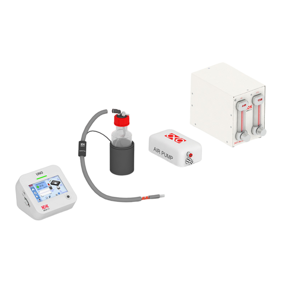
Equipment Overview UNO-T Figure 1 illustrates the equipment overview for UNO-T configuration: UNO-CONTROLLER (x1), temperature controller Y-CABLE-1 (x1). To connect chamber’s base and lid to the temperature controller. 24V-DC Power Adapter (x1). OBJ-COLLAR (optional) Okolab H301 incubating chamber (required, to be ordered separately). -
Page 10: Uno-T-H-Co2
10. Humidifer (x1). It is composed of a glass bottle, Humidifier Bottle, with TUBE E (6 mm O.D. silicone tube with a glass bubbler at the end) and its heater, Humidifier Heater. 11. Heated Tube (x1). Use Heated Tube to connect the Humidifier to Okolab H301 incubating chamber. 12. Okolab H301 incubating chamber (required, to be ordered separately). - Page 11 13. Humidifier (x1). It is composed of a glass bottle, Humidifier Bottle, with TUBE E (6 mm OD silicon tube with a glass bubbler at the end) and its heater, Humidifier Heater. 14. Heated Tube (x1). Use Heated Tube to connect the Humidifier to Okolab H301 incubating chamber. 15. Okolab H301 incubating chamber (required, to be ordered separately).
-
Page 12: Compatibility
Note ► For U.S. shipment, Okolab provides a push to fit adapter from ¼” to 6 mm rigid tube. Compatibility UNO-STAGE-TOP-INCUBATOR is compatible with: • Okolab H301 incubating chamber (required, to be ordered separately), with heated lid and base, chamber riser with one or more plate adapters. Refer to paragraph 8.2.2.1 for the complete list of compatible H301 incubating chamber. -
Page 13: Equipment Description
Equipment Description Figure 5 illustrates UNO-CONTROLLER left panel: MINI-USB port. To connect the supplied MINI-USB-OTG cable or a standard MINI-USB cable. RS232 Serial port. To connect a standard RS232 Serial cable. Figure 5. UNO-CONTROLLER Left Panel Overview. Figure 6 illustrated UNO-CONTROLLER rear panel: Power input Base / Lid connector. - Page 14 Figure 7. UNO-CONTROLLER Front Panel Overview.
-
Page 15: Installation
Connection of the Chamber Base and the Chamber Lid Follow the instructions below to connect the Base and the Lid of the Okolab H301 incubating chamber to UNO-CONTROLLER (see Figure 8): 1. - Page 16 Connect the rigid end of Heated Tube to the Gas Outlet connector of Humidifier. Connect the silicon end of Heated Tube to the gas input connector located on a corner of Okolab H301 incubating chamber (see Figure 10). Tip ► Make sure to push the tubes all the way into the connectors thus avoiding any gas leak.
- Page 17 Heated Tube Humidifier H301 Chamber Figure 10. Heated Tube - Assembly. Follow the instructions below to connect GF-MIXER-HM, the Humidity Module, to UNO-CONTROLLER (see Figure 11): 1. Connect the Y-CABLE-2 connector to “Humidifier/Heated Tube” connector on the rear panel of UNO- CONTROLLER.
-
Page 18: Gas Connection
Gas Connection 7.3.1 Gas connection for UNO-T-H-PREMIXED UNO-T-H-PREMIXED is suitable or applications with premixed gas supply. Follow the steps below for a correct installation: 1. Install the GF-REGULATOR between the premixed gas supply and the Humidifier (see Figure 13). Use TUBE-A to connect the premixed gas supply to the push to fit input connector for a 6 mm O.D. - Page 19 Tip ► If the desired gas flow rate is 0.27 l/min, the pressure of the GF-REGULATOR has to be set at 0.6 barg (8.7 psig). Tip ► Okolab suggests setting the gas flow rate in the range 0.3 – 0.4 l/min. If the total control volume is Figure 14 shows how to use the GF-REGULATOR correctly: A.
-
Page 20: Gas Connection For Uno-T-H-Co2
7.3.2 Gas Connection for UNO-T-H-CO2 UNO-T-H-CO2 is suitable for applications with 100% CO2 and background air. Follow the steps below for a correct installation: 1. Install the pressure gauge between the CO2 supply and the 2GF-MIXER (see Figure 15). The pressure gauge is equipped with a push to fit input connector for a 6 mm O.D. - Page 21 TUBE-A NOT supplied Figure 15.UNO-T-H-CO2 - Inlet gas connection. OKO-AP features two alternative outlet air flow rate: Low Flow (in the range 0 – 0.5 l/min) and High Flow (in the range 0.5l/min – 1.0 l/min). Slide to the right the manual switch placed on the bottom panel of OKO-AP to select the High Flow mode (see image A in Figure 16).
-
Page 22: How To Use 2Gf-Mixer
Follow the instructions below: 1. Open the gas valves about 15 minutes before inserting the sample in the H301 Okolab incubating chamber. 2. Table 2 reports the CO2 and air flow rates to be set in order to obtain a concentration of CO2 equal to 5% at the 2GF-MIXER outlet. - Page 23 Figure 19. 2GF-MIXER - Graduated scales. Tip ► If you use a premixed gas tank supply (95% air and 5% CO2), Okolab suggests that the premixed gas supply should be connected to the “Air in” connector on the rear panel of the 2GF-MIXER. The air flow rate...
-
Page 24: Connection Oft Sensor
Connection of T Sensor Plug the T Sensor to the green port placed on the rear panel of UNO-CONTROLLER (see Figure 20). UNO-CONTROLLER T Sensor Figure 20. T Sensor - Connection. Tip ► T Sensor has two connector pins of different dimensions. Make sure to follow the right direction of entry into the openings UNO-CONTROLLER’s green connector. -
Page 25: Mini-Usb Port
3. Connect the WP-CABLE to “Obj. Heater” connector on the rear panel of UNO-CONTROLLER (see Figure 22). UNO-CONTROLLER WP-CABLE OBJ-COLLAR Figure 22. OBJ-COLLAR - Connection. Tip ► Connecting cables are equipped with identification tags to guide you through the installation process. MINI-USB port The MINI-USB provides the connection for the supplied MINI-USB-OTG cable or a standard MINI-USB cable. -
Page 26: Rs232 Serial Port
• DATA-LOG software. The software allows to log and analyze the data provided by UNO-CONTROLLER via PC. Refer to DATA-LOG user manual for more info. • (OKOLAB API) integration third party software http://www.oko- lab.com/support#soft_int_tools. MINI-USB cable Figure 24. MINI-USB cable - Connection. - Page 27 Without a serial port COM, to install the Serial Communication cable to your PC, you need to install a USB to serial converter following the manufacturer instructions. If you want to log, you have to use the COM port number that Windows assigned to the drive.
-
Page 28: User Interface
User Interface This chapter describes the user interface of UNO-CONTROLLER. Home page Figure 26. Homepage of UNO-CONTROLLER Touch Screen Display. 1. Info. Press here to access the Info page (see paragraph 8.5). 2. Home. To open the Homepage. 3. Settings. Press here to access system options and settings (see paragraph 8.2). 4. -
Page 29: How To Enter The Setpoint
8.1.1 How to enter the Setpoint To input a new Temperature Setpoint, touch the corresponding tab, as indicated in Figure 27 a. The Setpoint regulation page will appear as in the Figure 27 b. You can modify the Setpoint by clicking on + and – (pointer 1 in Figure 27 b). -
Page 30: Controller Status: Colours Led And Meaning
The RED color indicates that there is a problem with the unit itself (for example the sensor is broken). The system is on alarm. Turn the system off, wait for 5 minutes, and turn it back on. If the color is still red, contact Okolab at www.oko-lab.com for support. Controller Status: ALARM Tip ►... -
Page 31: Settings
Settings Press on Settings icon to enter the Settings menu, as shown in the Figure 30 a. Figure 30. How to enter the Settings menu (a – b). Press the arrow in the bottom right corner of the page (see Figure 31 a) to open the second page of the Settings menu (see Figure 31 b). -
Page 32: Chamber Control Mode
Figure 33. Settings – Control Mode – Chamber Control mode (a – b). In Chamber Control mode, the temperature of the Chamber Base and Chamber Lid of Okolab H301 incubating chamber are strictly controlled to guarantee that the sample temperature is maintained at the desired set point value. -
Page 33: Sample Control Mode
Chambered Glass Slide, etc.) or a well (Reference Well) adjacent to your sample position. Tip ► Check if your Okolab H301 incubating chamber provides the Reference Well. If you use a dish, secure the T Sensor to the bottom of the dish with commercial adhesive tape as shown in Figure 36 a. - Page 34 Figure 36. T Sensor attached on the bottom of the Petri dish (a -b). When possible close the Petri dish with its own plastic lid (or with Okolab SENSOR LID, to be ordered separately) and place it in the appropriate sample holder.
-
Page 35: Chamber & Insert
Figure 39. How to enter the Chamber & Insert menu (a - b). Here you have to set the model of Okolab H301 incubating chamber that you have purchased and the type of sample adapter being inserted into it. Depending on these selections, UNO-CONTROLLER will automatically change the control settings. - Page 36 ±1°C for a temperature set point of 37°C. The offset of the Chamber Base and the Chamber Lid has been optimized to guarantee a uniform temperature for all the wells. Okolab suggests operating using factory offset values. To view factory offset value click on Offset button (see Figure 42 a).
-
Page 37: Compatible Okolab H301 Incubating Chamber List
8.2.2.1 Compatible Okolab H301 incubating chamber List Table 4 reports all the available Okolab H301 incubating chambers for UNO-STAGE-TOP-INCUBATOR. Chambers: H301-K-FRAME H301-NIKON-TI-S-ER H301-OLYMPUS-IX3-SVR H301-PRIOR-H117 Detail: Fits standard XY stages with k-frame insert (160x110mm). Chambers: H301-LUDL96A602 H301-MCL-Z100/500 H301-NIKON-NZ100/200/500-N H301-PI-736-160x110 Detail: Fits Z-piezo stages models listed. - Page 38 Incubating chamber for PhaseView Alpha3 system small version. Chambers: H301-ALPHA3-LARGE Detail: Incubating chamber for PhaseView Alpha3 system large version. Chambers: H301-MIZAR-TILT Detail: Incubating chamber for Mizar Tilt modular Light Sheet system. Chambers: CUSTOM Detail: Parameters for custom chambers. Table 4. Compatible Okolab H301 incubating chamber List.
-
Page 39: Objective Heater
8.2.3 Objective Heater Press on Objective Heater icon (see Figure 43 a) to enter the Objective Heater menu, see Figure 43 b. Note ► The Objective Heater is enabled by default. Disable the Objective Heater if it is not in use; otherwise, UNO-CONTROLL will be in alarm. -
Page 40: Humidity
Figure 45. Settings – Obj. Heater –Enabled - menu (a – b). Four options are available: 1. By pressing Log button (see pointer 1 in Figure 45in b) you can select parameters obtained by calibrations previously performed (see paragraph 8.2.5.3). 2. - Page 41 Figure 47. How to enter the Humidity menu (a -b). GF-MIXER-HM (Humidity Module) supplies a humidity level up to90% of Relative Humidity acting on the temperatures of both the Humidifier Bottle and the Heated Tube. In order to make the humidity control work properly, the user has to set the actual Room Temperature- Press the + / - icons to set the Room Temperature (see pointer 1 in Figure 48 b) and press Save to confirm (see pointer 2 in Figure 48 b).
-
Page 42: Calibrations
Figure 49. Settings – Humidity – Offset (a – b). Note ► To disable the Humidity check off the checkbox “Humidity control enabled” (see pointer 1 in Figure 50) and press OK to confirm (see pointer 2 in Figure 50). Figure 50. -
Page 43: Chamber
Figure 52. Settings - Calibrations - menu (a - b). 1. Chamber (see pointer 1 in Figure 52). Here you can perform the calibration of the incubating chamber, see paragraph 8.2.5.1. 2. T Sensor (see pointer 2 in Figure 52). Here you can perform the calibration of the T Sensor, see paragraph 8.2.5.2. - Page 44 Figure 54. Settings – Calibrations - Chamber – Log (a – b). UNO-CONTROLLER stores the parameters obtained by previous calibrations for each combination of selected chamber with its selected sample holder. You can recover calibration parameters only for the selected pair of chamber and its sample holder. 2.
- Page 45 Figure 55. T Sensor attached on the bottom of the Petri dish (a -b). Tip ► Use the same dish that you use in regular practice. • Fill the sample holder with water or oil to the level used during standard operation. Make sure the tip of the T Sensor is immersed in the liquid.
-
Page 46: T Sensor
Figure 57. Settings – Calibrations – Chamber – Calibrate – Options (a – b). 8.2.5.2 T Sensor Press on T Sensor icon , to enter the T Sensor calibration submenu (see Figure 58). Figure 58. Settings-Calibrations-T Sensor (a – b). At this point you can choose: 1. - Page 47 Press on Set (see pointer 4 in Figure 58 b) to adjust to reading of the T Sensor against the reading of the certified thermometer. Tip ► Press on icon to receive instructions on how to calibrate the T Sensor. Note ►Okolab recommends using a certified thermometer as external reference.
-
Page 48: Obj. Heater
8.2.5.3 Obj. Heater Press on Obj icon , to enter the Objective Heater calibration submenu (see Figure 62). Note ►Make sure that the Objective Heater is enabled (see paragraph 8.2.3). Figure 62. Settings – Calibrations - Obj. Heater (a – b). At this point you can choose: 1. - Page 49 Figure 64. T Sensor attached on the bottom of the Petri dish (a -b). Tip ► Use the same dish that you use in regular practice. • Fill the sample holder with water or oil to the level used during standard operation. Make sure the tip of the T Sensor is immersed in the liquid.
- Page 50 Note ►Make sure that a Chamber Calibration has been performed (see paragraph 8.2.5.1). A distinction should be made between the Chamber Control mode and the Sample Control mode. To start the Obj. Heater calibration in Chamber Control mode, follow the instructions below: •...
-
Page 51: Logging
Figure 67. Settings – Calibrations – Obj. Heater – Calibrate (a – b). By clicking Options (see pointer 1 in Figure 68 a), the menu Advanced calibration parameters will appear (see Figure 68 b) and, here, it is possible to set the calibration Accuracy (see pointer 2 in Figure 68 b) and Precision (see pointer 3 in Figure 68 b). - Page 52 Figure 69. How to enter the Logging menu (a – b). 2. Flag Internal memory in the page that appears (see Figure 70). Figure 70. Settings – Logging - menu (a-b). Tip ► When activating the logging on the internal memory, you can access the Logging page also by pressing the activated logging icon on the Homepage, as shown in Figure 71.
- Page 53 Figure 72. Settings – Logging – Logging time (a – b). 4. Choose how you want to organize the data when downloaded, by pressing on Day, Week or Month, see Figure 72 a. Tip ►If you select Day, the data will be split in files, each one containing the data of one day. If you select Week, the data will be split in files, each one containing the data of one week.
- Page 54 Note ►The available memory depends on the time interval you have inserted in the Logging page. The default logging Time Interval is 30 seconds. Figure 75. Settings – Logging - Internal log (a - b). To download the data, press on To USB or on Erase if you want to delete the data, see Figure 75 b. Figure 76.
-
Page 55: Alarms
Figure 78. Homepage - Logging to USB drive. Note ► When connecting the USB drive to UNO-CONTROLLER, a USB drive icon appears on the Homepage. If you activate the logging on USB drive, a red dot appears on the USB drive, to remind that the USB drive should not be disconnected while data logging is ongoing see Figure 78. -
Page 56: Display
Note ►After any change in the Setpoint value the device enters into a transient regime. Note ►For example, if the Tolerance from setpoint is 0.5 or greater (for a temperature setpoint of 37°C and the temperature reaches a value equal or less than 36.5°C or equal or more than 37.5°C) for a period of time equal or longer than 10 minutes (Time set in Figure 79 b) then the system triggers an Alarm. -
Page 57: Options
Figure 82. How to enter the Display menu (a – b). 8.2.8.1 Options Press the Options icon (see Figure 83 a) to enter the Display Options page. The Display Options menu allows to set the time frame in which the minimum and maximum temperature values are collected. To insert the time frame, press the + / - icons or scroll the Chart history length bar (1 in Figure 83 b). -
Page 58: Calibration
Figure 84. Settings – Display - Brightness (a – b). 8.2.8.3 Calibration When pressing the Calibration icon (see Figure 85), the procedure for the calibration of the touch screen will start. Figure 85. Settings – Display - Calibration. 8.2.8.4 Date & Time To set Date &... -
Page 59: Visual Effects
Figure 86. Settings – Display - Date and Time (a – b). Note ► The default time format is a 24-hour clock. Tip ► Deselect the 24 hours box, if you want to use the hour format based on 12 hours (see Figure 87 a). If you have selected 12 hour clock format, press on am or pm button (see pointer 1 in Figure 87 b) when you set the time. - Page 60 (see Figure 90 a) to access to password settings page and flag on Password Enabled to enable the password use (see Figure 90 b). Figure 90. How to enter the Password menu (a - b). Note ► The default password is okolab.
- Page 61 Figure 92. How to enter the Summary page (a – b). Note ►This page contains data useful for technical/control reasons. In case you requested support from one of Okolab engineers you may be asked for some of these data. 8.2.8.9 Auto on/off UNO-CONTROLLER can be programmed to turn on and/or turn off automatically at specific times.
- Page 62 Figure 93. How to enter the Auto on/off menu (a – b). Press on Auto turn on icon to enter in Auto Turn on menu (see Figure 94 a). Set the switching on time, the first number is for setting hour (from 0 to 23), the second number is for minutes (see pointer 1 in Figure 94 b).
- Page 63 Figure 96. How to enter the Status Overview page (a - b). Note ►This page contains data useful for technical/control reasons. In case you requested support from one of Okolab engineers you may be asked for some of these data Icon and Glance Mode View UNO-CONTROLLER features two display modalities: Icon mode and Glance Mode, as shown in Figure 97 a and b.
- Page 64 Figure 98. How to enter the Info Page (a – b). Tip ►Please have this information handy when contacting Okolab for support...
- Page 65 Touch Screen Calibration Keep pressed the ON/OFF button on UNO-CONTROLLER for 7 seconds to start the Display Calibration (see Figure 99). While holding the button, the pop-up message shown in Figure 100 a appears. Then tap blue calibration dots until the calibration is complete (see Figure 100 b). Figure 99.
- Page 66 Maintenance Verify periodically the status of all hoses/tubing. If some hoses/tubing is damaged, contact Okolab to receive assistance. After 2 years, disconnect all polyurethane tubing, cut the last 1 cm of the tubing and reconnect them.
- Page 67 To contact one of our engineers please write to support@oko-lab.com or contact us through the live chat in www.oko-lab.com. You can request a remote support session anytime. Please, do not hesitate to contact Okolab should you need any further commercial information or technical support. HARDWARE SUPPORT: sibillo@oko-lab.com Phone...
- Page 68 Power Consumption 120 W max Dimension UNO-CONTROLLER (LxWxH) 129mmx125mmx104mm UNO-CONTROLLER Weight 0.400 Kg Table 5. UNO-T Technical Specifications. UNO-T-H-PREMIXED – Technical Specifications Control Range: 3°C above ambient temperature (minimum temperature set point 25°C) to 60°C Step size: 0.1°C Accuracy: Temperature •...
- Page 69 Power Consumption 120 W max Dimension UNO-CONTROLLER (LxWxH) 129mmx125mmx104mm UNO-CONTROLLER Weight 0.400 Kg OKO-AP (LxWxH) 96mmx160mmx57mm OKO-AP Weight 0.350 Kg Humidifier Bottle diameter 72 mm, height 190 mm 2GF-MIXER (LxWxH) 126mmx200mmx178mm 2GF-MIXER Weight 3.0 Kg Table 7. UNO-T-H-CO2 Technical Specifications...
- Page 70 13 Troubleshooting We have collected in the table below some frequently asked questions, please contact Okolab if you need support. Symptom Probable cause Remedy The current temperature values are Check the cable connections and if the Acoustic alarm sounds far temperature set-points...
- Page 71 Figure 11. GF-MIXER-HM - Connection....................................13 Figure 12. GF-REGULATOR - front and rear view (a - b)..............................14 Figure 13. UNO-T-H-PREMIXED - Gas connection................................15 Figure 14. GF-REGULATION - Use......................................16 Figure 15.UNO-T-H-CO2 - Inlet gas connection................................... 17 Figure 16.
- Page 72 Table 2. 2GF-MIXER flow rate regulation for 5% CO2 concentration........................19 Table 3. Sensors lid codes..........................................30 Table 4. Compatible Okolab H301 incubating chamber List............................34 Table 5. UNO-T Technical Specifications....................................64 Table 6. UNO-T-H-PREMIXED Technical specifications..............................64 Table 7.
- Page 73 LIMITATION OF LIABILITY: the total liability of Okolab S.r.l. shall not exceed the purchase price of the component upon which liability is based. In NO event shall Okolab S.r.l. be liable for consequential, incidental or special damage.
Need help?
Do you have a question about the UNO-T and is the answer not in the manual?
Questions and answers