Table of Contents
Advertisement
Quick Links
1. Introduction
1.1 General Specifications
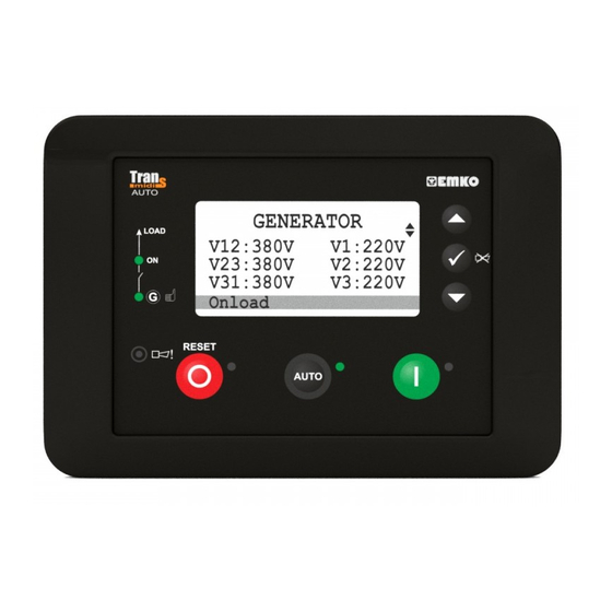
The unit provides automatic start and stop the engine and protect the generator system. Both
automatic and manual control is possible. A test mode is also available which allows the generator to
be run for checking the generator system.
The unit calculates engine RPM from Magnetic Pickup sensor input (Trans-MidiAUTO.MPU devices
only) and/or generator voltage signal. At Trans-MidiAUTO.CAN devices, unit gets engine RPM
information from J1939 ECU.
The unit monitors J1939 ECU messages and provides remote start/stop control via J1939 protocol
(supported ECUs: Volvo EMS2, Volvo EDC4, Perkins, Scania S6 and standard messages).
The unit monitors generator operation and gives warning of any faults that are detected.
The configurable input-3 can be used as the water level sensing input.
1.2 Warranty
EMKO Elektronik warrants that the equipment delivered is free from defects in material and workmanship.
This warranty is provided for a period of two years. The warranty period starts from the delivery date. This
warranty is in force if duty and responsibilities which are determined in warranty document and instruction
manual performs by the customer completely.
1.3 Maintenance
Repairs should only be performed by trained and specialized personnel. Cut power to the device before
accessing internal parts.
Do not clean the case with hydrocarbon-based solvents (Petrol, Trichlorethylene etc.). Use of these
solvents can reduce the mechanical reliability of the device. Use a cloth dampened in ethyl alcohol or
water to clean the external plastic case.
TRANS-MIDIAUTO
AUTOMATIC START UNIT
Introduction Brochure. ENG TRANS-MIDIAUTO 01 V10 10/20
Advertisement
Table of Contents

Subscribe to Our Youtube Channel
Related Manuals for EMKO Trans-midiAUTO.MPU.232 Trans-midiAUTO.CAN.232


Summary of Contents for EMKO Trans-midiAUTO.MPU.232 Trans-midiAUTO.CAN.232
- Page 1 The configurable input-3 can be used as the water level sensing input. 1.2 Warranty EMKO Elektronik warrants that the equipment delivered is free from defects in material and workmanship. This warranty is provided for a period of two years. The warranty period starts from the delivery date. This warranty is in force if duty and responsibilities which are determined in warranty document and instruction manual performs by the customer completely.
- Page 2 2. Installation Ýçindekiler Before beginning installation of this product, please read the instruction manual and warnings below carefully. A visual inspection of this product for possible damage occured during shipment is recommended before installation. It is your responsibility to ensure that qualified mechanical and electrical technicians install this product.
-
Page 3: Electrical Connection
2.3 Electrical Connection TRANS-MidiAUTO three phase connections schematic BATTERY - FUSE-4 BATTERY + Configurable Output-6 Configurable Output-5 Configurable Output-4 Configurable Output-3 Crank Or Configurable Output-2 FUSE-3 Fuel Or Configurable Output-1 FUSE-2 FUSE-1 Emergency Stop or Configurable Input-1 Remote Start or Configurable Input-2 Water Level or Generator... - Page 4 3. Changing And Saving Parameters Values Operation Screen GENERATOR PROGRAM V12: 380V V1: 220V Program Operator setting V23: 380V V2: 220V ü Language ü Technician setting ü V31: 380V V3: 220V Event Log Factory adjustment On load Press Enter button to Press Enter button to Press the Up or Down buttons to...
- Page 5 4. Parameters 4.1 Operator Parameters 4.1.1 Generator GENERATOR VOLT LEVEL ( Generator-> Volt level Default Unit Under volt shutdown 60(dis) Generator Under Voltage Shutdown Under volt prealarm Generator Under Voltage Pre-Alarm 60(dis) Under volt reset Generator Under Voltage Pre-Alarm Reset Over volt shutdown Generator Over Voltage Shutdown Over volt prealarm...
-
Page 6: System Network
4.2 Technician Parameters 4.2.1 System SYSTEM NETWORK ( System->Network Default Unit CT ratio 9999 Current Transformer Ratio PT ratio Voltage Transformer Ratio Type of AC system 0- 1 Phase 2 Wire Select AC system; 1- 3 Phase 4 Wire 2- 2 Phase 3 Wire L1-L2 3- 2 Phase 3 Wire L1-L3 Phase sequence Generator Phase Sequence (dis, L123 or L321) -
Page 7: Date & Time Set
COMMUNICATION ( Default Unit System->Communication Slave address Slave Address Baud rate Baud Rate: 0 - 1200 baud 1 - 2400 baud 2 - 4800 baud 3 - 9600 baud 4 - 19200 baud 5 - 38400 baud Parity Parity: 0 - NONE EVEN Stop bit... - Page 8 4.2.2 Generator GENERATOR VOLT LEVEL ( Generator-> Volt level Default Unit Under volt shutdown Generator Under Voltage Shutdown 60(dis) Under volt prealarm Generator Under Voltage Pre-Alarm 60(dis) Under volt reset Generator Under Voltage Pre-Alarm Reset Over volt shutdown Generator Over Voltage Shutdown Over volt prealarm Generator Over Voltage Pre-Alarm 60(dis)
- Page 9 POWER LEVEL ( Generator->Power level Default Unit Under power Generator Under Power 9999 Under power prealarm Generator Under Power Pre-Alarm 0(dis) 9999 Under power reset Generator Under Power Pre-Alarm Reset 9999 Under power act. Generator Under Power Actions 0(dis) 0(dis) Disable Warning (Alarm Only, No Shutdown) Electrical Trip (Alarm/Off Load Generator...
- Page 10 4.2.3 Engine ENGINE START OPTIONS ( Default Unit Engine->Starting options Horn prior start ENABL/DISBL DISBL Audible Alarm Prior To Starting En/Dis No. of crank attemp Number Of Start Attempts Cranking time Cranking Time Crank rest time Crank Rest Time Pickup fail dely* 10.0 Pickup Sensor Fail Delay ENG.
- Page 11 CANBUS ECU ( Default Unit Engine->CanBus ECU Baud rate Baud Rate: kBaud 0: 20, 1: 50, 2: 100, 3: 125, 4: 250, 5: 500, 6: 800, 7: 1.000 J1939 ECU type 0(dis) J1939 ECU Type Selection: 0 - Disable 1 - Standard 2 - Volvo EMS1 3 - Volvo EMS2 4 - Volvo EMS2b...
- Page 12 CANBUS ERROR SET ( Engine->CanBus error set Default Unit CAN fault actions Can Fault Actions: 0- Disable 1- Warning Non-Latching 2- Warning (Alarm Only, No Shutdown) 3- Electrical Trip (Alarm/Off Load Generator Followed By Shutdown After Cooling) 0(dis) 4- Shutdown (Alarm And Shutdown) CAN fault activation Can Fault Activation: 0- Active From Starting...
-
Page 13: Engine Maintenance
ENGINE MAINTENANCE ( Unit Default Engine->Maintenance Running hour interval 0(dis) 9999 Hour Running Hours Interval Maint. date interval 0(dis) Month Maintenance Date Interval Eng. stop when maint ENABL/DISBL DISBL Force Engine Shutdown When Maintenance Is Due Eng. running hour(lsb) Engine Running Hour (Lsb) Eng. -
Page 14: Engine General
Start time on Exercise Sta rt Time Friday 0.00 23.59 0.00 H.Min Stop time on 0.00 0.00 H.Min Exercise Stop Time Friday 23.59 Start time on 0.00 23.59 0.00 H.Min Exercise Sta rt Time Friday Stop time on Exercise Stop Time Friday 0.00 23.59... - Page 15 4.2.4 Inputs SENDER INPUTS ( Inputs->Sender inputs Default Unit Oil pressure unit Oil Pressure Unit BAR/PSI/KPA Oil press. input type Oil Pressure Input Type 0 - Not Used (Disable) 0 (dis) 1 - Digital NC 2 - Digital NO 3 - VDO 5 BAR 4 - VDO 7 BAR 5 - VDO 10 BAR 6 - DATCON 5 BAR...
- Page 16 Conf. AI1 high reset Configurable Analog Input-1 3000 High Reset Configurable Analog Input-1 Conf. AI1 high shutd. 0 (dis) 3000 0 (dis) High Shutdown Conf. AI1 control ON Configurable Analog Input-1 0 (dis) 3000 0 (dis) control ON Conf. AI1 control OFF 3000 Configurable Analog Input-1 control OFF...
- Page 17 SENDER LINEARISATION ( Inputs->Sender linearisation Default Unit Oil pressure sender 1 1300 Oil Pressure Sender Point-1 Oil pressure 1 30.0 Oil Pressure Point-1 Oil pressure sender 2 1300 Oil Pressure Sender Point-2 Oil pressure 2 30.0 Oil Pressure Point-2 Oil pressure sender 3 1300 Oil Pressure Sender Point-3 Oil pressure 3...
- Page 18 Conf. AI1 sender 6 1300 Configurable Analog Input-1 Sender Point-6 Conf. AI1 value 6 3000 Configurable Analog Input-1 Point-6 Conf. AI1 sender 7 1300 Configurable Analog Input-1 Sender Point-7 Conf. AI1 value 7 3000 Configurable Analog Input-1 Point-7 Conf. AI1 sender 8 1300 Configurable Analog Input-1 Sender Point-8 Conf.
- Page 19 CONF. INPUT-X ( Inputs->Conf. input-x Default Unit Dis,user conf.or list in1, 2=2 0- Disable 0(dis) in3=1 1- User Configured in4, 5=2 2- Select From List Polarity in1, 3=1 0- Normally Open (Close To Activate) in2, 4=0 1- Normally Close (Open To Activate) in5=0 Indication If User Configured...
- Page 20 4.2.5 Outputs CONF. OUTPUT-1 ( Outputs->Conf. output-1 Default Unit Polarity 0- Normally Open (Close To Activate) 1- Normally Close (Open To Activate) Function 0-NOT USED 1-AIR FLAP CONTROL 2-ALARM RESET 3-AUDIBLE ALARM 4-AUTO START INHIBIT 5-RESERVED 6-BATTERY HIGH VOLTAGE 7-BATTERY LOW VOLTAGE 8-CALLING FOR SCHEDULED RUN(EXERCISE) 9-CAN ECU POWER (only available at Trans-MidiAUTO.CAN)
- Page 21 CONF. OUTPUT-2 ( Outputs->Conf. output-2 Default Unit Polarity 0- Normally Open (Close To Activate) 1- Normally Close (Open To Activate) Function The same as Configurable Output-1 options CONF. OUTPUT-3 ( Outputs->Conf. output-3 Default Unit Polarity 0- Normally Open (Close To Activate) 1- Normally Close (Open To Activate) Function The same as Configurable Output-1 options...
- Page 22 4.2.6 Timers START TIMERS ( Unit Default Timers->Start timers Remote start delay 3600 Remote Start Delay Pre-heat Pre-Heat Pre-heat bypass Pre-Heat Bypass Safety on delay Safety On Delay Warming up time Warmup Time Horn duration 0 (dis) Horn Duration Chg. excitation time 0 99(cont) Charge Excitation Time Cooling fan time...
- Page 23 4.2.8 User Adjustment GEN. VOLTAGE OFFSET ( Default Unit User adjustment->Gen. voltage offset Gen. V1 offset Generator V1 Offset Gen. V offset Generator V Offset Gen. V offset Generator V Offset CURRENT OFFSET ( Default Unit User adjustment-> Current offset Current I1 offset Current I1 Offset Current I offset...
-
Page 24: Specifications
5. Specifications Equipment use : Electrical control equipment for generating sets. Housing & Mounting : 158 mm x 111 mm x 67 mm. (including connectors) . Plastic housing for panel mounting Panel Cut-Out : 120mm x 94mm. Protection IP65 at front panel. Weight : Approximately 0,26 Kg. -
Page 25: Other Informations
GSM-GPRS+GPS feature Trans-midiAUTO.CAN.485.GPRS+GPS: Auto Start GenSet controller, CanBus J1939 ECU communication,RS-485 communication, GSM-GPRS+GPS feature Thank you very much for your preference to use Emko Elektronik products, please visit our web page to download detailed user Your Technology Partner manual. www.emkoelektronik.com.tr...
Need help?
Do you have a question about the Trans-midiAUTO.MPU.232 Trans-midiAUTO.CAN.232 and is the answer not in the manual?
Questions and answers