Table of Contents
Advertisement
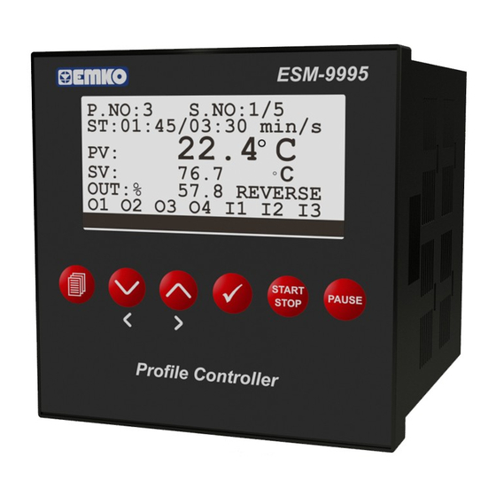
ESM-9995 96 x 96 DIN 1/4
- 100 program, 1000 step control
- Programmable relay functions per steps
- Universal process input (TC, RTD, mV
- 6 different electric cut-out behaviour
- ON/OFF, P, PI, PD, PID reverse and direct control
- Motorized valve control with feedback
- Motorized valve control floating control
- Auto-Tuning and Self-Tuning (automatic calculations of PID
parameters)
- Automatic / Manual operating modes
- Bumpless transfer ability
- Sensor Error detection
- Remote Set control
- Re-transmission (for process, SET values)
- Operating with Real Time Clock (RTC)
- 8 set point which is selected with digital inputs
- ModBus ASCII/RTU communication protocol
Universal Input
Profile Controller
Introduction Manual. ENG ESM-9995 02 V02 07/13
ES -99 95
M
, V
, mA
)
Advertisement
Table of Contents

Related Manuals for EMKO ESM-9995


Summary of Contents for EMKO ESM-9995
- Page 1 - Sensor Error detection - Remote Set control - Re-transmission (for process, SET values) - Operating with Real Time Clock (RTC) - 8 set point which is selected with digital inputs - ModBus ASCII/RTU communication protocol Introduction Manual. ENG ESM-9995 02 V02 07/13...
-
Page 2: Table Of Contents
CONTENTS 1.PREFACE............................... Page 4 1.1 GENERAL SPECIFICATIONS 1.2 ORDERING INFORMATION 1.3 WARRANTY 1.4 MAINTENANCE Page 6 2.INSTALLATION............................2.1 GENERAL DESCRIPTION 2.2 DIMENSIONS 2.3 PANEL CUT-OUT 2.4 ENVIRONMENTAL RATINGS 2.5 PANEL MOUNTING 2.6 INSTALLATION FIXING CLAMP 2.7 REMOVING FROM THE PANEL Page 11 3.ELECTRICAL WIRINGS........................ - Page 3 EU DECLARATION OF CONFORMITY Manufacturer’s Name : EMKO ELEKTRONIK A.S. Manufacturer’s Address : DOSAB, Karanfil Sk., No:6, 16369 Bursa, TURKEY The manufacturer hereby declares that the product: Product Name : Profile Controller Unit Type Number : ESM-9995 Product Category : Electrical equipment for measurement, control and...
-
Page 4: Preface
Plastic Profile Control Petro-Chemistry PID Process Control Textile Heater Failure detection Automative Machine production industries 1.1 General Specifications Standard ESM-9995 Universal Supply Input 100-240 V , 50/60Hz Power Supply Low Voltage (optional) Input Supply Input 50/60Hz ,24V Universal Process Input... -
Page 5: Ordering Information
-1999,9999 1.3 Warranty EMKO Elektronik warrants that the equipment delivered is free from defects in material and workmanship. This warranty is provided for a period of two years. The warranty period starts from the delivery date. This warranty is in force if duty and responsibilities which are determined in warranty document and instruction manual performs by the customer completely. -
Page 6: Installation
2.Installation Before beginning installation of this product, please read the instruction manual and warnings below carefully. In package , - One piece unit - Two pieces mounting clamps - One piece instruction manual A visual inspection of this product for possible damage occured during shipment is recommended before installation. -
Page 7: General Description
Panel surface (maximum thickness 15 mm / 0.59 inch) Front Panel IP65 protection NEMA 4X 2.2 Dimensions Maximum 15mm / 0.59 inch Dimentions ESM-9995 START PAUSE STOP Profile Controller 96mm / 3.78 inch 11.5 ± 1 mm / 84mm / 0.45 inch... -
Page 8: Panel Cut-Out
2.3 Panel Cut-out 129 mm / 5.08 inch (min) 92mm / 3.62 inch... -
Page 9: Environmental Ratings
2.4 Environmental Ratings Operating Conditions Operating Temperature : 0 to 50 °C Max. Operating Humidity : 90% Rh (non-condensing) Altitude : Up to 2000m. Forbidden Conditions: Corrosive atmosphere Explosive atmosphere Home applications (The unit is only for industrial applications) 2.5 Panel Mounting 1-Before mounting the device in your panel, make sure that the cut-out is of the right size. -
Page 10: Installation Fixing Clamp
2.6 Installation Fixing Clamp The unit is designed for panel mounting. 1-Insert the unit in the panel cut-out from the front side. 2- Insert the mounting clamps to the holes that located top and bottom sides of device and screw up the fixing screws until the unit completely immobile within the panel... -
Page 11: Electrical Wirings
3.Electrical Wirings You must ensure that the device is correctly configured for your application. Incorrect configuration could result in damage to the process being controlled, and/or personal injury. It is your responsibility, as the installer, to ensure that the configuration is correct. Device parameters has factory default values. -
Page 12: Electrical Wiring Diagram
Digital Inputs Motorized Valve 0 to 10V input Feedback input 0 to 20mA A.IN 2 0 to 20mA POT.(1K) Pt-100 P/N : ESM-9995 Communication CAT II Socket A.OUT1 A.OUT2 0 to 10V 0 to 10V Output 1 Output 2 Output 3... -
Page 13: Definition Of Front Panel And Accessing To The Parameters
4.Definition of Front Panel and Accessing to the Parameters 4.1 Definition of Front Panel MAIN OPERATION SCREEN VIEW Step No Program No P.NO:3 S.NO:1/5 Step elapsed time ST:01:45/03:30 min/s Step time 22.4 C Process Value & Unit ° Set Value & Unit 76.7 °... -
Page 14: Access The Step Settings
4.2. Access the Step Settings Pages OPERATING PAGES VIEW ESM-9995 P.NO:3 S.NO:1/5 ST:01:45/03:30 min/s 22.4 C ° 76.7 ° OUT:% 57.8 REVERSE 01 02 03 04 I1 I2 I3 START PAUSE STOP Profile Controller (Main Operating Page) STEP INFORMATIONS PNO:1... -
Page 15: Access To Menus
4.3. Access to Menus P.NO:3 S.NO:1/5 ST:01:45/03:30 min/s Holding 1 sec. 22.4 C ° 76.7 ° OUT:% 57.8 REVERSE O1 O2 O3 O4 I1 I2 I3 OPERATOR SECTION TECHNICIAN SECTION TECHNICIAN SECTION OPERATOR SECTION DEVICE SETTING PAGE OPERATOR PARAMETERS TECHNICIAN SECTION UNIVERSAL INPUT PAGE TECHNICIAN SECTION REMOTE SET PAGE... -
Page 16: Changing The Parameter Values
4.4. Changing the Parameter values P.NO:1 S.NO:1/5 OPERATOR SECTION ST:01:45/03:30 min/s 22.4 C ° 76.7 ° Holding 1 sec. OUT:% 57.8 REVERSE O1 O2 O3 O4 I1 I2 I3 OPERATOR SECTION OPERATOR SECTION OPERATOR PARAMETERS OPERATOR PARAMETERS 1 OPERATING PROG.NO OPERATOR SECTION OPERATOR SECTION OPERATOR PARAMETERS... -
Page 17: Adjusting The Profile Program
4.5. Adjusting the Profile Program ESM-9995 P.NO:3 S.NO:1/5 ST:01:45/03:30 min/s 22.4 C ° 76.7 ° OUT:% 57.8 REVERSE 01 02 03 04 I1 I2 I3 START PAUSE STOP Profile Controller If OK button is pressed, program setting page is PNO:1 FNC:EDIT entered and “FNC”... - Page 18 PSJ:Program Select Join PNO:1 FNC: EDIT At the end of the Program, if this number PRC:1 PSJ:SB exists, device joins this program number. SJD:OFF It can be adjusted from OFF to 100. SDT:OFF PDT:OFF SJD:Start Program Join with Digital input PNO:1 FNC: EDIT...
- Page 19 Step NO PNO:1 FNC: EDIT Step number is chosen. SNO: SSV:0.0 °C STG:00.00 SRP:0 STS:1 SEV:0/0/0/0/0/0 Step Set Value PNO:1 FNC:EDIT Step Set Value is entering. SNO:1 SSV:0.0 °C STG:00.00 SRP:0 STS:1 SEV:0/0/0/0/0/0 Step Time/Gradient PNO:1 FNC:EDIT Step Time or Gradient is entering. SNO:1 SSV:23.8 °C...
- Page 20 If A24 PROFILE TYPE parameter is selected as 1, Profile Program Setting Page is shown as bellow. PROG NO parameter is used PROG NO: to select program number that will be changed. STEP NO:1 STP SET: 0.0 °C STP TIM: STP ALR:0 STP EVN:0 STEP NO parameter is used...
-
Page 21: Copy Profile Program
4.6. Copy Profile Program COPY : To Copy Program to PNO:1 FNC: EDIT another program area. PRC:0 PSJ:OFF SJD:OFF SDT:OFF PDT: OFF Change Function using increment and PNO:1 FNC: COPY decrement button. Select “COPY”. PRC:0 PSJ:OFF SJD:OFF SDT:OFF PDT: OFF Press OK button and cursor position COPY PNO:1... - Page 22 If target program is full, then “FIRSTLY DELETE TARGET” message is shown. PNO:12 FNC: COPY PRN:4 PNO:4 FUNC: FNC: COPY COPY PRC:0 PRC:0 PRC:0 PSJ:OFF PSJ:DSB PSJ:OFF SJD:OFF SJD:DSB SJD:OFF SDT:OFF SDT:DSB SDT:OFF PDT:OFF PDT:DSB PDT:OFF PROG. COPY SUCCESFUL FIRSTLY DELETE TARGET FIRSTLY DELETE TARGET Device waits for OK button pressed to confirm the operation status.
-
Page 23: Delete Profile Program
4.7. Delete Profile Program PNO:1 FNC: EDIT PRC:0 PSJ:OFF SJD:OFF SDT:OFF PDT:OFF Change Function using increment and PNO:1 FNC: decrement button. Select “DEL”. PRC:0 PSJ:OFF SJD:OFF SDT:OFF PDT:OFF Press OK button and cursor position PNO:1 FNC: becomes “PNO:” tab. Select program PRC:0 PSJ:OFF number, that you want to delete. -
Page 24: Delete Step
4.8. Delete Step PNO:1 FNC: EDIT EDIT SNO:1 SSV:23.8 °C STG:11.45 SRP:1 STS:1 SEV:1/0/0/0/0/0 Choose “DEL” function using PNO:1 FNC: EDIT increment and decrement buttons SNO:1 SSV:23.8 °C STG:11.45 SRP:1 STS:1 SEV:1/0/0/0/0/0 If OK button is pressed, cursor position PNO:1 FNC:DEL becomes “PNO:”... -
Page 25: Copy Step
4.9. Copy Step PNO:1 FNC: EDIT EDIT SNO:1 SSV:23.8 °C STG:11.45 SRP:1 STS:1 SEV:1/0/0/0/0/0 Choose “COPY” function using COPY PNO:1 FNC: EDIT increment and decrement buttons SNO:1 SSV:23.8 °C STG:11.45 SRP:1 STS:1 SEV:1/0/0/0/0/0 If OK button is pressed, cursor PNO:1 EDIT FNC:COPY position becomes “PNO:”... -
Page 26: Insert Step
4.10. Insert Step PNO:1 FNC: EDIT EDIT SNO:1 SSV:23.8 °C STG:11.45 SRP:1 STS:1 SEV:1/0/0/0/0/0 Choose “INS” function using PNO:1 FNC: EDIT increment and decrement buttons SNO:1 SSV:23.8 °C STG:11.45 SRP:1 STS:1 SEV:1/0/0/0/0/0 If OK button is pressed, cursor PNO:1 FNC:INS position becomes “PNO:”... -
Page 27: Running Of Profile Program
4.11. Running of Profile Program While profile program isn’t running, the message “PROGRAM STOPPED” appears on the screen. To start to run the program, you should press the button START STOP After selecting the number of program that is desired to run, you should press START/STOP button again to start the program, . -
Page 28: Parameters
5. Parameters 5.1. Operator Parameters OPERATOR PARAMETERS Default Unit Mdb.Add. 40001 Operating Program number A01 OPERATING PR. NO Process Set value 40002 -9999 9999 A02 PROCESS SETVALUE Alarm 1 Set value 40003 -9999 9999 A03 ALARM 1 SETVALUE Alarm 2 Set value 40004 -9999 9999... -
Page 29: Technician Parameters
5.2. Technician Parameters If the device is configured as Profile Control; DEVICE SETTING PAGE Default Unit Mdb.Add Device Operating Type PROCSS PROFIL PROFIL 51856 B01 OPERATING MODE (PROCSS,PROFIL) Maximum Step Number 51857 1000 B02 MAX STEP NUMBER Maximum Program Number 51858 1000 B03 MAX PROGRAM NUMB... - Page 30 REMOTE SET PAGE Default Unit Mdb.Add. Remote Set Selection 51914 D01 REMOTE SET SELCT Input Type 0-20mA 4-20mA 0-20mA 51915 D02 INPUT TYPES (0-20mA,4-20mA) Calibration Type FIXED DUALP FIXED 51916 D03 CALIBR. TYPE (FIXED,DUALP) 2 point calibration min -1999 9999 51917 D04 DUAL PO.
- Page 31 ANALOG OUTPUT 1 PAGE Default Unit Mdb.Add. Output Type Sel. 0-20MA 2-10V 0-20MA 52003 52003 J01 OUTPUT TYPE SEL. (0-10V/0-20MA/2-10V/4-20MA) Function Selection REVERS RETRAN 52004 J02 FUNCTION SELECT (OFF,REVERS,DIRECT,TETRAN) Retransfer Type Sel. RTPROC RTSET RTPROC 52005 J03 RETRAN. TYPE SEL (RTPROC,RTSET,RTERRO) Default Unit...
- Page 32 Default Unit RELAY OUTPUT 2 PAGE Mdb.Add. Function Selection REVERS LO.OUT DIRECT 52047 M01 FUNCTION SELECT (REVERS,DIRECT,LLO.OUT) Control Algorithm ONOFF 52048 M02 CONTROL ALGORIT (ONOFF,PID) ON/OFF Hysteresis 9999 52049 M03 ON/OFF HYS. ON/OFF Hysteresis Function 52050 M04 ON/OFF HYS FUNC. ON/OFF On delay time Sec.
- Page 33 RELAY OUTPUT 4 PAGE Default Unit Mdb.Add. Function Selection REVERS LO.OUT REVERS 52095 O01 FUNCTION SELECT (REVERS,DIRECT,LLO.OUT) Control Algorithm ONOFF ONOFF 52096 O02 CONTROL ALGORIT (ONOFF,PID) ON/OFF Hysteresis 9999 52097 O03 ON/OFF HYS. ON/OFF Hysteresis Function 52098 O04 ON/OFF HYS FUNC. Sec.
- Page 34 6. Modbus Adresses 6.1 Read Input Registers Modbus Adresses MODBUS ADRESS PARAMATER 30001 PROCESS VALUE PID OUTPUT VALUE 30002 30003 SET VALUE 30004 ANALOG OUTPUT - 1 VALUE ANALOG OUTPUT - 2 VALUE 30005 30006 MOTORIZED VALVE FEEDBACK VALUE 30007 STEP REPEAT CYCLE 30008 RUNNING STEP TIME SET...
- Page 35 6.1 Profile Programs Modbus Adresses MODBUS ADDRESS PROGRAM PARAMETERS 40028 + 8*(N-1)+0 N. PROGRAM REPEAT CYCLE 40028 + 8*(N-1)+1 N. PROGRAM SELECT JOIN 40028 + 8*(N-1)+2 N. PROGRAM NEXT PROGRAM SELECT SEGMENT 40028 + 8*(N-1)+3 N. PROGRAM START TIME 40028 + 8*(N-1)+4 N.
-
Page 36: Modbuss Addresses
To calculate modbus address of any of Nth step’s parameter of Mth program, you may use the following equations. PROFILE STEPS PARAMETERS MODBUS ADDRESS 40828 + 11*((M-1)*MSN +N-1)+0 Nth STEP of Mth PROGRAM SET VALUE 40828 + 11*((M-1)*MSN +N-1)+1 Nth STEP of Mth PROGRAM SET TIME 40828 + 11*((M-1)*MSN +N-1)+2 Nth STEP of Mth PROGRAM GRADIENT 40828 + 11*((M-1)*MSN +N-1)+3... - Page 37 Emko Elektronik Sanayi ve Ticaret A.Þ. Demirtaþ Organize Sanayi Bölgesi Karanfil Sk. No:6 16369 BURSA/TURKEY Phone : +90 224 261 1900 Fax : +90 224 261 1912 Thank you very much for your preference to use Emko Elektronik Products. Your Technology Partner www.emkoelektronik.com.tr...
Need help?
Do you have a question about the ESM-9995 and is the answer not in the manual?
Questions and answers