
Related Manuals for Hioki 3283-20


Summary of Contents for Hioki 3283-20
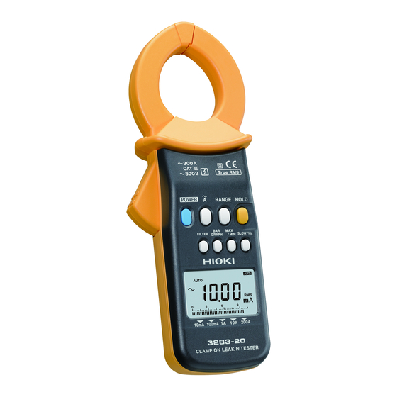
- Page 1 3283-20 Instruction Manual CLAMP ON LEAK HiTESTER June 2015 Edition 1 3283C981-00 15-06H...
-
Page 3: Table Of Contents
Contents Introduction .................1 Checking Package Contents ..........1 Safety Information ..............2 Operating Precautions ............7 Overview Overview and Features ......... 11 Parts and Functions ........13 Liquid Crystal Display ........15 Pre-measurement Preparation Flow of Measurement ........19 Installing/Replacing the Battery ....20 Inspection Prior to Use .........23 Attaching the Hand Strap ......24 Performing Measurements Measuring Leakage Current ......25... - Page 4 Contents Checking Maximum, Minimum and Average Values (Recording Function – REC) ..............37 Bar graph displays (BAR GRAPH) ......39 Limiting Battery's Power Consumption (Auto power-off function – APS) ....41 Disabling the Buzzer ........42 Specifications 4.1 Measurement Specifications ......43 AC current: Amperes rms (display of true rms) ..44 Frequency Hz ............
-
Page 5: Introduction
Introduction Introduction Thank you for choosing the Hioki 3283-20 Clamp On Leak HiTester. To ensure that your instrument performs as designed over the long term, please handle this instruction manual carefully and keep it handy for future reference. Checking Package Contents Once you have received the instrument, verify that it has not suffered any damage during shipment before using it. -
Page 6: Safety Information
Safety Information Safety Information The 3283-20 has been designed and tested in accordance with the IEC 61010 safety standard and shipped in a safe state. However, failure to adhere to the precautionary information and follow the instructions provided in this manual may render safety-related functionality provided by the instrument inoperable. - Page 7 Safety Information Safety-related notations This manual classifies safety information on the basis of the severity of the associated risk and hazard level using the following categories. Indicates an imminent hazard that could lead to serious DANGER injury or death. Indicates a hazard that could lead to serious injury or WARNING death.
- Page 8 Safety Information Symbols displayed on the instrument Indicates the need for caution or a hazard. When this symbol is displayed on the instrument, refer to the corresponding section of the instruction manual. Indicates AC (Alternating Current). Indicates DC (Direct Current). Indicates that the instrument may be connected to or disconnected from a live circuit.
- Page 9 Safety Information A different display is used in the case below. Over-range indication (p. 1 7). Other notations Bold text is used to indicate language used on keys and other HOLD ( Bold ) controls. [ ] Language from the screen is enclosed in brackets Accuracy We define measurement tolerances in terms of rdg.
- Page 10 CAT II to CAT IV measurement category. Doing so may result in a serious accident. The 3283-20 conforms to the safety requirements for CAT III (300 V) measuring instruments. CAT Ⅱ: When directly measuring the electrical outlet receptacles...
-
Page 11: Operating Precautions
Checking the instrument before use Verify that the instrument operates normally to ensure that no damage occurred during storage or shipping. If you find any damage, contact your authorized Hioki distributor or reseller. Installation WARNING Installing the instrument in inappropriate locations may cause a malfunction of instrument or may give rise to an accident. - Page 12 Operating Precautions Handling of the instrument DANGER • Do not input a voltage or current in excess of the ratings indicated on instrument labeling or the measurement range listed in the specifications. Doing so may cause damage to, or heating of, the instrument, leading to bodily injury.
- Page 13 Operating Precautions CAUTION • Be careful to avoid dropping the instrument or otherwise subjecting them to mechanical shock, which could damage the mating surfaces of the jaw and adversely affect measurement. • Do not place foreign objects between the mating faces of the jaw or insert foreign objects into the gaps of the jaw.
- Page 14 Operating Precautions...
-
Page 15: Overview
Overview 1.1 Overview and Features The 3283-20 is designed for wide-range measurement of current in live circuits, from very small leak currents up to load currents of 200 amperes. The jaws are made of material with high magnetic permeability to minimize adverse effects from external magnetic fields and error due to the position of the conductor measured, thus raising accuracy. - Page 16 Overview and Features components to be superimposed on leak current waveforms. The filter functions allow measurement of two kinds of leak current: the kind caused by insulation faults and the kind that contains high-frequency components. Minimized effects from external magnetic fields and conductor position The jaws are made of material with high magnetic permeability, allowing precise measurement near to...
-
Page 17: Parts And Functions
Parts and Functions 1.2 Parts and Functions Front and rear Barrier Operation Rear cover lever (p. 2 0) Control keys (p. 1 4) display (p. 1 5) Strap slit (p. 2 4) - Page 18 Parts and Functions Control keys Power turned on while Normally holding key down POWER key Turns the power on/off – Turns the recording – function off (p. 3 8) RANGE key Switches the range Disables the buzzer (p. 4 2) (p. ...
-
Page 19: Liquid Crystal Display
Liquid Crystal Display 1.3 Liquid Crystal Display AC measurement (p. 2 5) Hold data (p. 3 6) Auto ranging is enabled (p. 2 9) AUTO Update display approx. 1 time/3 seconds (p. 3 0) SLOW Recording function is on (p. 3 7) Maximum value (p. ... - Page 20 Liquid Crystal Display Battery remaining power display When the power is turned on, all the LCD's segments light up. Then the model name is displayed, and the bar graph shows the battery power for 1 second. Bar graph display with fresh battery If the battery remaining power is zero,...
- Page 21 Liquid Crystal Display Over-range indication [O.L.] will be displayed if the measured current or frequency is beyond the measurement limit. When this display occurs, select an appropriate range.
- Page 22 Liquid Crystal Display...
-
Page 23: Pre-Measurement Preparation
Pre-measurement Preparation 2.1 Flow of Measurement Before using the instrument, be sure to read “Operating Precautions” (p. 7 ) Preparing and connecting-up Install the battery (p. 2 0). Do pre-use checks (p. 2 3). (As necessary) Attach the hand strap (p. 2 4). Measuring Turn the power on. -
Page 24: Installing/Replacing The Battery
If you lose or damage the screws, contact your authorized Hioki distributor or reseller. • Handle and dispose of batteries in accordance with local regulations. - Page 25 Installing/Replacing the Battery CAUTION Heed the following instructions to avoid battery performance drop or leakage. • Pay attention to the polarity markings "+" and "–", so that you do not insert the battery the wrong way around. • Do not use a battery beyond its recommended use period. •...
- Page 26 Installing/Replacing the Battery Prepare the following: • A layered-type alkaline battery Rear (6LR61) or a layered-type manganese dry cell battery (6F22) • Phillips screwdriver Turn the instrument's power 3, 8 off. 4, 7 Loosen the rear cover's two fastening screws, using the Phillips screwdriver.
-
Page 27: Inspection Prior To Use
Before using the instrument for the first time, inspect it carefully to ensure that no damage occurred during shipping. If damage is evident, or if it fails to operate according to the specifications, contact your dealer or Hioki representative. Exterior appearance check Check item Action •... -
Page 28: Attaching The Hand Strap
Attaching the Hand Strap 2.4 Attaching the Hand Strap Strap slits on the back of the instrument can be used for attaching the included hand strap. Use the hand strap to help prevent accidental dropping of the instrument. CAUTION Attach the strap securely, by inserting it through the strap slits on the instrument. -
Page 29: Performing Measurements
Performing Measurements 3.1 Measuring Leakage Current DANGER To prevent electric shock, do not touch any part beyond the barrier during use (p. 1 3). Clamp the conductor at the center of the jaw. To measure the ground wire of a circuit, clamp the ground wire only. in the figure) (See To measure all the wires of a circuit, clamp them all together in a... - Page 30 Measuring Leakage Current Clamp all three of the circuit's wires in a bundle 3-phase 3-wire circuit Load equipment Ground wire Ground wire • To measure a single-phase 2-wire circuit, clamp both of the circuit's wires together. • To measure a 3-phase 3-wire circuit, clamp all 3 of the circuit's wires bundled together.
- Page 31 Measuring Leakage Current • Do not input current that exceeds the current range's maximum continuous input. • Measurement may not be accurate in the cases below. (1) If there is large current (of about 100 A) flowing through a nearby electric line. (2) If you use the instrument to measure the waveforms on the secondary side of an inverter, or other special waveforms.
-
Page 32: Locating An Insulation Failure
Measuring Leakage Current Locating an insulation failure For a transformer, first measure the ground wire to determine in the figure), then use the the overall circuit leak current (see variation in the leak current to diagnose the presence or absence of leakage. -
Page 33: Selecting The Measurement Range
Measuring Leakage Current Selecting the measurement range You can set auto or manual ranging. • Auto ranging The optimal range for the measured values is set automatically. Setting is fixed to a particular range. • Manual ranging With the frequency display, only auto ranging is available. Auto ranging Measurement will begin with auto ranging when the power is turned on. -
Page 34: Setting A Slower Display Update Rate (Slow)
Measuring Leakage Current Setting a slower display update rate (SLOW) If the displayed current value fluctuates rapidly and is hard to read, you can set a slower update rate (approx. 1 time/3 seconds) by pressing the SLOW/Hz key, to make the value easier to read. [SLOW] [Hz] [RMS]... -
Page 35: Measuring An Intensely Fluctuating Load Current
Measuring Leakage Current Measuring an intensely fluctuating load current First set the FAST display update rate and set the appropriate range using the RANGE key. Then do the measurement. NORMAL FAST (Split-second display each key is pressed) time Press twice in succession Set to a fixed current range. -
Page 36: Obtaining Bar Graph Displays (Bar Graph)
Measuring Leakage Current Obtaining bar graph displays (BAR GRAPH) You can have the current range displayed as a bar graph. The bar graph will show the rms value of the measured current. The bar graph display update rate will be FAST (approx. 4 times/second). -
Page 37: Displaying The Frequency (Hz)
Measuring Leakage Current Displaying the frequency (Hz) When [SLOW] is displayed: [SLOW] [Hz] [RMS] The frequency of the current being measured will be displayed. If there is no input, or input is lower than 30 Hz, "----" will be displayed. •... -
Page 38: Measuring Load Current
Measuring Leakage Current Measuring load current To measure load current, clamp just one wire of the conductor. The measurement will not be possible if you clamp both wires of a single-phase cable or all 3 wires of a 3-phase cable. •... -
Page 39: Reducing Noise (Filter Function - Filter)
Reducing Noise (Filter Function – FILTER) 3.2 Reducing Noise (Filter Function – FILTER) The widespread use of switching power supplies and equipment incorporating inverter technology can cause high-frequency components to be superimposed on leak current waveforms. Use the filter function to eliminate unwanted high-frequency components. FILTER OFF FILTER ON The frequency bandwidth with the filter function enabled is limited to... -
Page 40: Hold Data (Data Hold Function - Hold)
Hold Data (Data Hold Function – HOLD) 3.3 Hold Data (Data Hold Function – HOLD) Use this to freeze the displayed data (put it on hold) for easy reading. -
Page 41: Checking Maximum, Minimum And Average Values (Recording Function - Rec)
Checking Maximum, Minimum and Average Values (Recording Function – REC) Checking Maximum, Minimum and Average Values (Recording Function – REC) Use the recording function to display the maximum/minimum measurement value, the average of the maximum and minimum, or the instantaneous value. Select the current range. - Page 42 Checking Maximum, Minimum and Average Values (Recording Function – REC) Halt the recording function. lights up) lights, [REC] Maximum value [MAX] Minimum value [MIN] Average value [AVE] Instantaneous value Turn the recording function back on. flashes) goes out, [REC] Turning the recording function off The maximum, minimum or average value will go out) will be cleared.
-
Page 43: Bar Graph Displays (Bar Graph)
Checking Maximum, Minimum and Average Values (Recording Function – REC) • The elapsed time count will stops for as long as lights steady. • Momentary power loss and power surges cannot be detected in this mode. • The maximum, minimum or average value will be cleared when the power is turned off. - Page 44 Checking Maximum, Minimum and Average Values (Recording Function – REC) When [min] is displayed at the right end of the bar graph: 1 segment in the bar graph represents 1 minute. The segment for the currently elapsing minute flashes, and when the minute has elapsed, that segment stops flashing and lights steady.
-
Page 45: Limiting Battery's Power Consumption (Auto Power-Off Function - Aps)
Limiting Battery's Power Consumption (Auto power-off function – APS) Limiting Battery's Power Consumption (Auto power-off function – APS) Use this to limit the battery's power consumption. It turns the power off automatically if the instrument is not operated for 10 minutes. The APS function is configured at the factory to enabled (this is the initial setting). -
Page 46: Disabling The Buzzer
Disabling the Buzzer 3.6 Disabling the Buzzer The buzzer is configured at the factory to enabled (this is the initial setting). To change this setting, first turn the power off. Press these simultaneously When you power up again, the buzzer will beep twice. Then it will be disabled. -
Page 47: Specifications
Conditions of Guaranteed accuracy period: 1 year guaranteed accuracy Guaranteed accuracy period from adjustment made by 1 year Hioki: Number of jaw opening- Up to 10,000 closings: Temperature and humidity for guaranteed accuracy: 23°C±5°C (73°F±9°F), 80% RH or less Battery low indicator must not be on. -
Page 48: Ac Current: Amperes Rms (Display Of True Rms)
Measurement Specifications AC current: A rms (display of true rms) Maximum Range Resolution Accuracy allowable (accuracy range) current FILTER OFF: 10.00 mA 0.01 mA (1.00 mA to 10.00 mA) 45 Hz to 66 Hz: ±1.0% rdg. ±5 dgt. 100.0 mA 0.1 mA (10.0 mA to 100.0 mA) 20 A... -
Page 49: Frequency Hz
General Specifications Frequency Hz Range (accuracy range) Resolution Accuracy 100.0 Hz (30.0 Hz to 99.9 Hz) 0.1 Hz ±0.3% rdg. ±1 dgt. 1000 Hz (95 Hz to 1000 Hz) 1 Hz ±1.0% rdg. ±1 dgt. The frequency range is set automatically. If you press the RANGE key in the frequency display mode, only the current range will be changed. - Page 50 General Specifications Battery low warning (This indicator lights to indicate the battery is low. When this is lighted, accuracy is not guaranteed.) Battery low power-off [bAtt] [Lo] → is displayed (using 7 segments), then power is shut off Data holding indication Auto power-off indication Other functions Filter functions...
- Page 51 General Specifications Standards Safety: EN61010 EMC: EN61326 Dust-proof, water-proof IP40 (EN60529) Operating temperature 0°C to 40°C (32°F to 104°F), 80% RH or less and humidity (non-condensing) Temperature In 0°C to 40°C (32°F to 104°F) range: 0.05 × characteristics accuracy specifications/°C Storage temperature -10°C to 50°C (14°F to 122°F) (non- condensing)
- Page 52 General Specifications...
-
Page 53: Maintenance And Servicing
Calibration of the instrument How often you should calibrate the instrument will depend on the usage conditions and the environment. Determine a calibration interval that is suited to your usage conditions and environment, and request to have calibration done by Hioki. - Page 54 It will also not be accurate if the jaws are deformed, by foreign matter or other cause. If the jaws become deformed, contact your authorized Hioki distributor or reseller. • To clean the instrument, wipe it gently with a soft cloth moistened with water or neutral detergent.
-
Page 55: Troubleshooting
Troubleshooting 5.2 Troubleshooting If a problem occurs with the instrument, first carry out the checks in "Troubleshooting checklist" below. If the problem persists, contact your authorized Hioki distributor or reseller. Troubleshooting checklist Problem Cause Solution Power will not turn on... -
Page 56: Error Displays
ROM. is displayed in the LCD display area, repair R/W error in single-chip [E. 002] is required. Contact microcomputer's internal RAM. your authorized Hioki [E. 003] distributor or reseller for EEPROM checksum error. [E. 004] repair. 5.4 Message Displays... - Page 57 Message Displays Definition Display See page There is abnormality in the internal ROM p.52 or EEPROM data. Have the instrument repaired. This is displayed if the measured current – or frequency is beyond the measurement limit. Select an appropriate range. When frequency display is set, this p.33 message indicates that there is no input or...
- Page 58 Error Displays...
- Page 59 13-09...
Need help?
Do you have a question about the 3283-20 and is the answer not in the manual?
Questions and answers