
Related Manuals for Hioki 3332


Summary of Contents for Hioki 3332
- Page 1 INSTRUCTION MANUAL For...は専用機種。複数の場合は「/」で区切る。不要の場合はとる。 形名を入力。 複数の場合は「/」で区切る。 3332 品名を入力。 POWER HiTESTER...
-
Page 3: Table Of Contents
Contents Introduction Inspection Safety Notes Notes on Use Chapter 1 Overview 1.1 Product Overview 1.2 Features 1.3 Identification of Controls and Indicators 1.4 Explanation for Keys 1.5 Display Reference 1.6 Handle and Stand Operations Chapter 2 Preparation for Measurement 2.1 Before Measurement 2.2 Simple Use 2.3 Making the Connections 2.3.1 Direct Connections... - Page 4 Chapter 4 Settings and Operations 4.1 Setting Items 4.2 Operating Setup Keys 4.3 Setting the Integration 4.3.1 Flowchart 4.3.2 Integration Setting Method 4.3.3 Integration Operation 4.3.4 Notes on Integration 4.3.5 Display Format of Integrating Value 4.4 Setting the Number of Averaging 4.4.1 Flowchart 4.4.2 Average Setting Method 4.5 Setting the Frequency...
- Page 5 Chapter 5 Setting and Measurement Example 5.1 Electrical Power Integration and Printer Output Examples 5.2 PT and CT Setting (Examples of Changing the Digits and Moving the Decimal Point) Chapter 6 Other Functions 6.1 When Power Fails 6.2 System Resetting 6.3 Error Indications 6.4 Changing the Power Calculation Circuit Clock Frequency...
- Page 6 8.3.12 Status Byte Register 8.3.13 Event Registers 8.3.14 GP-IB Commands 8.4 Command Reference 8.4.1 Standard Commands 8.4.2 Commands Specific to the 3332 8.5 Command Summary 8.5.1 Standard Commands 8.5.2 Commands Specific to the 3332 8.5.3 Valid Command According to Condition (Standard Command) 8.5.4 Valid Commands According to Condition...
- Page 7 Chapter 11 Specifications 11.1 General Specifications 11.2 Standard Specifications 11.3 Function Specifications Index INDEX 1...
- Page 9 (Shell DB19678-2) ■ Shipment If the 3332 unit is to be shipped or transported, the original packing should preferably be used. If this is not available, employ the following procedure. 1. Procure a packing case somewhat larger than the unit, such as a cardboard box.
-
Page 10: Safety Notes
──────────────────────────────────────────────────── Safety Notes This Instruction Manual provides information and warnings essential for operating this equipment in a safe manner and for maintaining it in safe operating condition. Before using this equipment, be sure to carefully read the following safety notes. This equipment is designed according to IEC 61010-1 Safety DANGER Standards, and has been tested for safety prior to shipment. - Page 11 ──────────────────────────────────────────────────── Measurement categories (Overvoltage categories) This instrument complies with CAT III safety requirements. To ensure safe operation of measurement instruments, IEC 61010 establishes safety standards for various electrical environments, categorized as CAT I to CAT IV, and called measurement categories. These are defined as follows. CATⅠ...
-
Page 12: Notes On Use
──────────────────────────────────────────────────── Notes on Use In order to ensure safe operation and to obtain maximum performance from the unit, observe the cautions listed below. DANGER This unit cannot be used on voltage lines of 600 Vrms. If the voltage exceeds 600 VAC, there will be a short-circuit accident or electrocution accident will result. - Page 13 HIOKI representative. Continued use of the unit could lead to fire or electric shock accidents.
- Page 14 0.2% of the measurement range for voltage, or less than 0.1% for active power. ・ The 3332 has a frequency measurement function, but this may produce unexpected results on a waveform which is severely distorted.
-
Page 15: Chapter 1 Overview
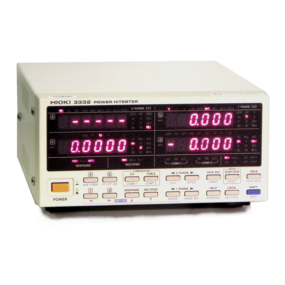
Chapter 1 Overview 1.1 Product Overview The 3332 POWER HiTESTER is a single-phase power measurement instrument for AC currents suitable for measuring the power of household electrical appliances. With this one unit, it is possible to measure voltage, current, active power, apparent power, reactive power, the power factor, phase angle, frequency, integrated value, and current peak value. -
Page 16: Features
──────────────────────────────────────────────────── 1.2 Features (1) Meets the safety requirements of IEC61010-1. (2) Wide broad band from 1 Hz to 100 kHz. (3) In reactive power, power factor, and phase indication, it is possible to recognize the phase is lead or lag. (4) The current range is wide. -
Page 17: Identification Of Controls And Indicators
──────────────────────────────────────────────────── 1.3 Identification of Controls and Indicators Display b Comparator display Condition of integration, Current range hold, settings Voltage range Display d Display a Display c Rectifier type Response speed Power switch See Section 1.4 Front Panel Current input terminal Voltage input terminal AC inlet (Power supply connector) RS-232C interface GP-IB interface Connector for external control and output... -
Page 18: Explanation For Keys
──────────────────────────────────────────────────── 1.4 Explanation for Keys To get the lower key indications, press the key first. SHIFT Notation Operations Section in this manual Changes the display on the display a. AVE・FREQ Sets the averaging count and frequency. 4.4, 4.5 AVE・FREQ Changes the display on the display b. PT・CT・SC Sets the PT/CT ratio and SC.(scaling) PT・CT・SC... - Page 19 ──────────────────────────────────────────────────── Notation Operations Section in this manual DATA OUT DATA OUT Outputs the measured value on the printer. 8.2, 8.7 PRINT Sets the printer interval and output item. PRINT START/STOP START/STOP Stops or starts the integration operation. 4.3.3 RESET Resets the integration value. 4.3.3 RESET HOLD...
-
Page 20: Display Reference
──────────────────────────────────────────────────── 1.5 Display Reference Indications Meaning Numbers Measurement value Indicates the prefix of unit. m, k, M Indicates the unit and display item. V, A, W, VA, var, PF, ○, Ip, Hz, Ah, +Wh, -Wh Voltage, current, active power, apparent power, reactive power, power factor, phase angle, current peak, frequency, integration current, positive ±Wh, TIME integration power, negative integration power, total integration power,... - Page 21 ──────────────────────────────────────────────────── Setting indications Meaning Average setting (number of times of average) Frequency setting (source, range) D/A output setting (item) Integration time setting Print out setting (time interval of printing, print item) PT (potential transformer) ratio setting CT (current transformer) ratio setting SC (scaling factor) setting Range selecting Comparator setting (in example, indicates the first table for channel 1)
- Page 22 Data is sent to printer after recovery from power failure. Resets the 3332 If the measured line is active when the 3332 is tuned on, the 3332 may malfunction or Err105 may be displayed. Thus, turn on the 3332 first and check that Err105 is not displayed, and then turn on the measured line.
-
Page 23: Handle And Stand Operations
──────────────────────────────────────────────────── 1.6 Handle and Stand Operations Removing the handle and stand Screws If the handle or feet are not required when the unit is rack-mounted, remove the fixing screws as shown in the figure on the left. 1. Remove the screws fixing on the handle. Handle 2. - Page 24 ──────────────────────────────────────────────────── ──────────────────────────────────────────────────── 1.6 Handle and Stand Operations...
-
Page 25: Chapter 2 Preparation For Measurement
──────────────────────────────────────────────────── Chapter 2 Preparation for Measurement 2.1 Before Measurement DANGER Do not exceed the maximum input voltage and current. Doing so can damage the unit or cause a serious accident. The maximum rated voltage between input terminals and ground is 600 Vrms. - Page 26 ・ If the measured line is active when the 3332 is tuned on, the 3332 may malfunction or Err105 may be displayed. Thus, turn on the 3332 first and check that Err105 is not displayed, and then turn on the measured line.
-
Page 27: Simple Use
Reference Make a connections. Section 2.3, "Making the Connections" Check that there is no short circuit. Connect the power cord of the 3332 to the outlet. Section 2.4, "Powering On " Turn the 3332 power on. Set the display item. -
Page 28: Making The Connections
──────────────────────────────────────────────────── 2.3 Making the Connections 2.3.1 Direct Connections Always connect the power meter to the secondary side of a breaker. DANGER On the secondary side of a breaker, even if the lines are shorted the breaker can trip and prevent an accident. On the primary side, however, the current capacity may be large, and in the event of a short-circuit there may be a serious accident. - Page 29 Method 1: Connect the voltage input terminals to the load side SOURCE side LOAD side LOAD side SOURCE side A B 3332 input terminals Method 2: Connect the current input terminals to the load side SOURCE side LOAD side SOURCE side LOAD side A...
-
Page 30: When Using Pt Or Ct
・ Depending on the input level, power meter losses may affect measured values. Refer to Section 2.3.3 for how to make connections that minimize power meter losses. SOURCE side LOAD side 3332 input terminals ──────────────────────────────────────────────────── 2.3 Making the Connections... -
Page 31: Notes On Connection Methods
──────────────────────────────────────────────────── 2.3.3 Notes on Connection Methods The power meter can be connected either using the method shown below in Fig.1, with the voltage measurement terminal connected on the load side, or as shown in Fig.2, with the current measurement terminal connected on the load side. -
Page 32: Powering On
HIOKI representative. Continued use of the unit could lead to fire or electric shock accidents. -
Page 33: Self Test
(Refer to Section 6.2, "System Resetting.") ・ If the measured line is active when the 3332 is tuned on, the 3332 may malfunction or Err105 may be displayed. Thus, turn on the 3332 first and check that Err105 is not displayed, and then turn on the measured line. - Page 34 ──────────────────────────────────────────────────── ──────────────────────────────────────────────────── 2.5 Self Test...
-
Page 35: Chapter 3 Basic Operation
──────────────────────────────────────────────────── Chapter 3 Basic Operation 3.1 Changing the Response Setting To enable stable measurements in the low frequency range, there are two response settings available. FAST (response time: 0.2 to 0.3 seconds) This allows stable measurement for a constant input of at least 45 Hz, but at frequencies below 45 Hz the measured value fluctuates. -
Page 36: Selecting The Rectifier Type
──────────────────────────────────────────────────── 3.2 Selecting the Rectifier Type (1) For voltage measurement this unit has three rectifier circuits. Before measurement, select the following type. Measure true RMS value ① RMS Measure average rectifier effective value converted for ② MEAN voltage, true RMS value for current ③... -
Page 37: Selecting The Display
──────────────────────────────────────────────────── 3.3 Selecting the Display Press the following keys, the function can be selected on each display. Display Function V, A, W, VA, var, PF, Hz, TIME V, A, W, Ip, Ah, +Wh, ±Wh V, A, W, VA, var, PF, ○, Ip, Hz, Ah, +Wh, -Wh, ±Wh, TIME V, A, W, VA, var, PF, ○, Ip, Hz, Ah, +Wh, -Wh, ±Wh, TIME Frequency Voltage... - Page 38 ──────────────────────────────────────────────────── The elapsed time is displayed as follows; From 0 minute to 999 hours From 1000 to 9999 hours and 59 minutes and 59 minutes From 1000 to 9999 hours 1000 hours and 59 minutes For the frequency display, the frequency measurement range is displayed as follows;...
-
Page 39: Selecting The Range
──────────────────────────────────────────────────── 3.4 Selecting the Range The maximum input voltage and current are 600 Vrms, 60 Arms. DANGER If the display value exceeds 600 V or 60 A, immediately stop measurement, cut the power to the line being measured. If measurement is continued exceeding the maximum input, the unit will be damaged and cause a serious accident. - Page 40 ③ When the measured value is under full scale of 30% and under 90% of the lower range: range down The 3332 can quickly move to the most suitable range through internal circuitry. Therefore, when the auto-ranging function is on, the 3332 will not necessarily go to the next range automatically.
-
Page 41: Holding The Display
──────────────────────────────────────────────────── 3.5 Holding the Display Press the key, the HOLD indicator is lit and preserve all measuring HOLD value at that point. (Hold state) Press the key again, this indicator goes off, and return normal HOLD measuring condition. 3.5.1 Restrictions During the Hold Status ・Shifting of response, range and rectifier type are not allowed. -
Page 42: Current Waveform Peak Hold Function And Maximum Value Measurement
──────────────────────────────────────────────────── 3.5.2 Current Waveform Peak Hold Function and Maximum Value Measurement These enable incoming current transients and maximum value of measurement items to be measured. (1) Press the → keys to start the peak hold function. While the peak SHIFT HOLD hold function is activated the HOLD indicator flashes. -
Page 43: Restrictions During The Peak Hold Status
──────────────────────────────────────────────────── 3.5.3 Restrictions During the Peak Hold Status ・Shifting of response, range and rectifier type are not allowed. ("Err.016" is displayed.) ・Even if the auto-ranging is set for voltage, current, or frequency the range cannot be changed. The range is fixed when the range is held. If the HOLD state is released, auto-ranging function restarts. - Page 44 ──────────────────────────────────────────────────── ──────────────────────────────────────────────────── 3.5 Holding the Display...
-
Page 45: Chapter 4 Settings And Operations
──────────────────────────────────────────────────── Chapter 4 Settings and Operations 4.1 Setting Items Items Display Section Setting the integrate time INTEG Selecting the number of averaging AVE・FREQ Selecting frequency measurement source and AVE・FREQ range Selecting the D/A output items Setting the PT (potential transformer) ratio PT・CT・SC Setting the CT (current transformer) ratio PT・CT・SC... -
Page 46: Operating Setup Keys
──────────────────────────────────────────────────── 4.2 Operating Setup Keys RESPONSE RECTIFIER ENTER SET UP "Setup key" means every key ( , , ▲ , ▼, and ) shown with blue ENTER letters in the figure above. These keys work as "Setup key" when setting the display (the SHIFT indicator is lit). -
Page 47: Setting The Integration
──────────────────────────────────────────────────── 4.3 Setting the Integration This sets integration time. When integrating, some limitations arise for this unit. In this section, the settings and the integrating method will be explained. 4.3.1 Flowchart Measurement display SHIFT INTEG Integration setting display 1. Set the integration time. Sets the integration 2. -
Page 48: Integration Operation
──────────────────────────────────────────────────── (2) Set the integration. Changing value 1. To select the integration time, press the ▲ or ▼ Setup key to change the value. ▼ ▲ Pressing Setup key moves flashing digit. Moving digits 2. The setting range of integrate time is 10 seconds to 10,000 hours. 3. -
Page 49: Notes On Integration
──────────────────────────────────────────────────── (3) Integration operation ・To start the integration after the previous integration value is reset: Press the → key (RUN indicator off), and then press SHIFT RESET key (RUN indicator is lit). The integration will start. START/STOP ・To add to the previous integration value. Press the key. - Page 50 ──────────────────────────────────────────────────── (2) The following settings cannot be changed during integration (RUN indicator lit) or integration stop (RUN indicator flashing), (Err.012 is displayed). RUN indicator Items Flashing Response ● ● Rectifier type - - Voltage and current range - - Averaging time ●...
- Page 51 ──────────────────────────────────────────────────── (7) When the integrate value achieves ±999999 MAh (MWh) or when the integrate time achieves 10000 hours, integrating cannot restart. ("Err.014" is displayed). In this case, press the → keys to reset integrating data. (RUN SHIFT RESET indicator off) (8) When the GP-IB setting is "Pr."...
-
Page 52: Display Format Of Integrating Value
──────────────────────────────────────────────────── 4.3.5 Display Format of Integrating Value The integration reset format is shown in Table 1 and 2. Digits of integrate value and integrate range format carry up or down simultaneously. The number of digits does not go below that when integration is reset. NOTE Table 1 Constitution of Current Integration Range Range [A]... - Page 53 ──────────────────────────────────────────────────── Integration resetting value Display format of current range and active power range applies to integrate value format under reset condition. Integrating value Range Display format Reset value format 30 W 30.000 W 30.0000 Wh 00.0000 Wh 1.5 kW 1.5000 kW 1.50000 kWh 0.00000 kWh Also in scaling display format applies to integrating value format.
-
Page 54: Setting The Number Of Averaging
──────────────────────────────────────────────────── 4.4 Setting the Number of Averaging When dealing with input that changes greatly, an average measurement value is displayed. This unit does measurement averaging by the number of settings. 4.4.1 Flowchart Measurement display SHIFT AVE・FREQ Average setting display 1. Set the number of times for averaging. Sets the averaging 2. - Page 55 ──────────────────────────────────────────────────── (2) Set the number of times for averaging. 1. Press the ▲ or ▼ key to change the averaging time in the desired column Increasing Decreasing when the displays on Display c are flashing. The setting range is 1 to 300. ▲...
-
Page 56: Setting The Frequency
──────────────────────────────────────────────────── 4.5 Setting the Frequency This sets the item to measure the frequency and the frequency range. Any frequency higher than the set range will be filtered out by an internal filter, so a stable frequency measurement can be made. 4.5.1 Flowchart Measurement display SHIFT... - Page 57 ──────────────────────────────────────────────────── (2) Set the frequency. 1. To select the frequency source, press the ▲ or ▼ key while the indication Setting frequency source and range of V, A on display d is flashing. 2. To select the frequency range, press the key and the setting display (500 ▼...
-
Page 58: Setting The D/A Output
──────────────────────────────────────────────────── 4.6 Setting the D/A Output To avoid damage to this unit, do not shorten the D/A output terminal CAUTION or input voltage. Select the D/A output item. This function will change one of the measurement items (voltage, current active power, apparent power, reactive power, power factor, phase angle, current peak, frequency, current integration value or power integration value) out of the measured value reached by the calculation expression, into analog waveform. - Page 59 ──────────────────────────────────────────────────── (2) Set the D/A output. 1. The measured data output from D/A is displayed as unit symbols on display d. When the indication on display d is flashing, the units can be changed the following way, by using the Setup keys. V A W VA var PF lp Hz Ah +Wh -Wh ±Wh ○...
- Page 60 ──────────────────────────────────────────────────── Lower than 0.4% f.s. becomes out of range. (Approx. 6.5 V) ・ In 500 Hz range, 500 Hz is 100% ・ In 100 kHz range, 100 kHz is 100% 2.5V ・ During "-----Hz" display, the output of the previous display is maintained. 100%fs.
-
Page 61: Setting The Pt (Potential Transformer) Ratio, Ct (Current Transformer) Ratio, And Sc (Scaling Factor)
──────────────────────────────────────────────────── 4.7 Setting the PT (Potential Transformer) Ratio, CT (Current Transformer) Ratio, and SC (Scaling Factor) When the secondary side of the PT is connected, by setting the PT ratio, it is possible to directly read the primary side of the PT. When the secondary side of the CT is connected, by setting the CT ratio, it is possible to directly read the primary side of the CT. - Page 62 ──────────────────────────────────────────────────── Moving digits 1. Using the ▲ or ▼ Setup key, set the PT ratio on display a, CT ratio on display b, and SC on display c, when the value is flashing. ▼ ▲ ① To set the PT ratio, raise or lower the flashing value indicated in display Moving decimal point a by using the ▲...
-
Page 63: Setting The Printer Output
──────────────────────────────────────────────────── 4.8 Setting the Printer Output When the interface setting is "Pr." mode, it is possible to print data using a standard printer connected through the GP-IB or RS-232C interface. This section describes how to set the printing interval and the items to be printed. 4.8.1 Flowchart Measurement display SHIFT... - Page 64 ──────────────────────────────────────────────────── (2) Set the print interval and print item. Moving digit 1. To move the flashing point, press the Setup key. 2. To set the value on the flashing digit, press the ▲ or ▼ Setup key. Setting the value ▼...
- Page 65 ──────────────────────────────────────────────────── 4. Select the item to be printed by using the key. At this time, unit Selecting item symbol and channel on display b and d are flashing to indicates the item. "on" shown on display d means that the item is printed. "oFF"...
-
Page 66: Connecting To The Printer
1. Match the settings of the printer and the 3332. (Baud rate, data length, stopbit, and parity) 2. For details on the setting method of the 3332, refer to Section 4.9, "Setting the Interface." 3. Connect the 3332 to the printer by using the RS-232C cable. -
Page 67: Setting The Interface
──────────────────────────────────────────────────── 4.9 Setting the Interface Sets the communication condition for GP-IB interface or RS-232C interface. 4.9.1 Flowchart Measurement display SHIFT INTERFACE GP-IB interface: Interface display Set the address. RS-232C interface: Select for the baud rate, data length, Sets for the interface parity, stop bit, and communication mode. - Page 68 ──────────────────────────────────────────────────── (2) Select the interface During flashing on display a, press the ▲ or ▼ key to select. The display for GP-IB, the address setting is displayed on display c. The display for RS-232C, the settings of data length, parity, stop bit, and communication mode on display d.
- Page 69 ──────────────────────────────────────────────────── (4) Move to the measurement display. Press the key. (SHIFT indicator off) INTERFACE EXIT Printer mode (Pr.) and Control mode (Co.) NOTE ・ When in Pr mode (PRINT indicator is lit), data such as interval print and manual print are output to the printer. ・...
-
Page 70: Setting The Comparator
──────────────────────────────────────────────────── 4.10 Setting the Comparator Decides which level the measurement target is on for a given measurement range. Turns the comparator function ON/OFF and sets the comparator item and limit value (table data). 4.10.1 Flowchart Measurement display SHIFT For channel 2, press COMP2 COMP1 Comparator setting display... - Page 71 ──────────────────────────────────────────────────── (2) Set the comparator. Changing value 1. Press the Setup key to move flashing digit. 2. Use the ▲ or ▼ key to make the following settings. ▼ ▲ Moving digits ・Select the table number when the table number on the display c is flashing. ・Enable or disable the comparator function when the ON/OFF indication on display d is flashing.
-
Page 72: Comparator Operation
──────────────────────────────────────────────────── 4.10.3 Comparator Operation When the comparator function is turned on, the following operation takes place. It makes no difference if the larger of the two values is set in display a or b. The two values are compared, and the larger one is made the HI limit value; the smaller one is made the LO limit value. -
Page 73: Displaying Comparator
──────────────────────────────────────────────────── 4.11 Displaying Comparator It is possible to check instantaneous values of comparator items while displaying limit values of comparator items. Moreover, instantaneous values of other measurement items can also be displayed singly. From the comparator display screen, it is also easy to change the comparator table number. - Page 74 ──────────────────────────────────────────────────── (2) Key operation Key operations on the comparator display screen are as follow: Pressing the key in normal mode moves to Comparator display TABLE screen. When the key is pressed: COMP CH1 Normal display When the TABLE key is pressed: 0 1 2 3 4 5 6 7 8 9 OFF Pressing the key changes to the desired measurement item on Display c.
- Page 75 ──────────────────────────────────────────────────── When the operating table is turned Off in the Comparator Settings, the display shows Off when returning to the Comparator display. ──────────────────────────────────────────────────── 4.11 Displaying Comparator...
-
Page 76: Selecting Range
──────────────────────────────────────────────────── 4.12 Selecting Range Ranges are often used in the 3332, so it comes equipped with a function to designate a required range in order to quickly move to that range; to move to a range with the keys; and with the auto-ranging function, to skip unnecessary ranges and quickly move to a required range. - Page 77 ──────────────────────────────────────────────────── (2) Set the range. Changing value 1. Press the key to select the range. 2. Set ON/OFF by pressing the ▲▼ keys in the selected range. ▼ ▲ When OFF is selected, move to a range by pressing the Moving digits keys, or use the auto-range setting to skip that range when moving to another range.
- Page 78 ──────────────────────────────────────────────────── ──────────────────────────────────────────────────── 4.12 Selecting Range...
-
Page 79: Chapter 5 Setting And Measurement Example
──────────────────────────────────────────────────── Chapter 5 Setting and Measurement Example 5.1 Electrical Power Integration and Printer Output Examples Will integrate electrical power of 200 V, 10 A max. for 1 hour. Every ten minutes, the integration time and +Wh will be printed. Reset the integration value. Set the voltage range to 300 V. - Page 80 ──────────────────────────────────────────────────── (1) Reset the integration value. (The RUN and HOLD indicators should be turned off.) 1. When the RUN indicator is lit, press the key to stop RUN HOLD START/STOP integration. The RUN indicator is flashing. 2. Press the keys to reset the integration value. The RUN SHIFT→RESET START/STOP indicator is turned off...
- Page 81 ──────────────────────────────────────────────────── (5) Set the print interval time to 10 minutes. SHIFT 1. Press the key during displaying integration setting (If the display is PRINT returned to the measurement display, press SHIFT→ PRINT PRINT Print interval Hours Minutes Seconds (10 second step) Print item 2.
- Page 82 ──────────────────────────────────────────────────── Using the RS-232C interface Setting example: baud rate: 9600, data length: 8, parity: no, stop bit: 1 1. Using the key, move the flashing point to display c. 2. Set the baud rate to "9600" on display c, using the ▲ or ▼ key. 3.
- Page 83 ──────────────────────────────────────────────────── ・ To continue integration ① When resetting the data and restarting. press the key and SHIFT→RESET then press the key. START/STOP ② When adding data and integrating, press key once. START/STOP ・ To stop operating Press the key once. The RUN indicator will flash and START/STOP "INTEGRATOR STOP"...
-
Page 84: And Ct Setting (Examples Of Changing The Digits And Moving The Decimal Point)
──────────────────────────────────────────────────── 5.2 PT and CT Setting (Examples of Changing the Digits and Moving the Decimal Point) Explains when using the following PT and CT: PT: primary side 6,600 V secondary 110 V (PT ratio 6,600÷110=60) CT: primary side 2,000 A secondary 5 A (CT ratio 2,000÷5=400) Reset the integration value. - Page 85 ──────────────────────────────────────────────────── 3. Set the PT ratio. To change the numerical value Press the ▲ or ▼ key 5 times to set to "6". To change the flashing to decimal point Press the key 4 times. To move the decimal point Press the ▲...
- Page 86 ──────────────────────────────────────────────────── (5) Move onto the measurement display. 1. Press the key, and the SHIFT indicator will turn off. The PT・CT・SC EXIT SC indicator (scaling) is lit. 2. The range setting corresponds to the secondary side of the voltage and current transformers. For example, with the 150 V, 5 A ranges, the ranges (resolution) of the scaled voltage, current, active power, and other values is as follows.
-
Page 87: Chapter 6 Other Functions
──────────────────────────────────────────────────── Chapter 6 Other Functions 6.1 When Power Fails (1) If a power failure occurs during integration, the integration restart (continues) after the power is restored. (2) When the GP-IB or RS-232C interface is in "Pr." mode, and if the power failed while integration was in progress, the measurement data at the time of power failure is printed, together with the integration elapsed time and a message "POWER FAILURE."... -
Page 88: System Resetting
──────────────────────────────────────────────────── 6.2 System Resetting To carry out a system reset, power on the unit, and hold down the SHIFT → keys during the self test. RESET This returns all of the settings to their initial values. (These are the same as the settings when the unit is initially shipped from the factory.) The integration elapsed time and integration value are also reset. -
Page 89: Error Indications
Indicate internal problems with the 3332. If these error indications appear, the unit requires repair. If the measured line is active when the 3332 is tuned on, the 3332 may malfunction or NOTE Err105 may be displayed. Thus, turn on the 3332 first and check that Err105 is not displayed, and then turn on the measured line. -
Page 90: Changing The Power Calculation Circuit Clock Frequency
──────────────────────────────────────────────────── 6.4 Changing the Power Calculation Circuit Clock Frequency Power measurement is carried out by direct input of the voltage and current waveforms to a multiplier, where an instantaneous power waveform is created. This is then passed through a smoothing circuit. Instantaneous power U input Multiplier... -
Page 91: Key Lock State
To release the key lock state (to turn off the KEYLOCK indicator) 1. Press the → keys again. SHIFT KEYLOCK 2. By using the controller, set the 3332 to remote condition. This does not inhibit the input of external control signals. SHIFT KEYLOCK ──────────────────────────────────────────────────── 6.5 Key Lock State... - Page 92 ──────────────────────────────────────────────────── ──────────────────────────────────────────────────── 6.5 Key Lock State...
-
Page 93: Chapter 7 External Control Terminal And Output Terminal
──────────────────────────────────────────────────── Chapter 7 External Control Terminal and Output Terminal 7.1 Connector Pin Assignment This connector is not for the RS-232C interface. Do not connect to CAUTION the personal computer. The unit may be damaged. Acceptable connecter (Cable side) (Standard accessory) ────────────────────────────────────────────────────... - Page 94 ──────────────────────────────────────────────────── Pin No. Meaning GND for analog output, waveform output, D/A output (A.GND) Output Analog output of voltage Output Analog output of current Output Analog output of active power Output D/A output (D/A OUT) HI output of comparator CH1 (HI1) Input IN output of comparator CH1 (IN1)
-
Page 95: Output Terminal
──────────────────────────────────────────────────── 7.2 Output Terminal To avoid damage to this unit, do not shorten the output terminal or CAUTION input voltage. U , I , P terminals) (1) Analog output ( Outputs ±5 V DCf.s. direct voltage for range. Outputs simultaneously for voltage (U), current (I) and active power (P). U m, I m terminals) (2) Monitor output ( Waveform output 1 Vf.s. -
Page 96: Comparator Output
However, it is necessary to wait until display becomes stable after inputting the measurement signal to carry out a real decision because of the relationship between 3332 analog response and display switching (analog output response time + 2 times display switching (approx. 0.4 seconds.)). -
Page 97: External Control Terminal
──────────────────────────────────────────────────── 7.4 External Control Terminal The external control terminals accept a 0/5 V logic signal or a relay contact short/open signal to control the unit. For details of the settings, refer to Sections 4.9, "Setting the Interface", Section 4.3, "Setting the Integration", and Section 4.8, "Setting the Printer Output". - Page 98 ──────────────────────────────────────────────────── (3) Comparator output hold (COMPHOLD1、COMPHOLD2) Comparator hold time 5 V (open) 400 ms or more 0 V (short) Hold end Hold start Comparator Hold Comparator operation is resumed when the logic signal is 5V within 200ms. While relay output is on hold, comparator decisions are not made. (4) Data output (Manual printing) (PRINT terminal) Over 300 ms 5 V (open)
-
Page 99: Making The Connections
──────────────────────────────────────────────────── 7.5 Making the Connections To avoid damage to this unit, do not shorten the output terminal or CAUTION input voltage. When connecting the external control terminal or output terminal, use the supplied connector (DB-25P-N, DB19678-2 Japan Aviation Electronics Industry, Limited) or equivalent. Soldered Connector cover Rear panel... - Page 100 ──────────────────────────────────────────────────── ──────────────────────────────────────────────────── 7.5 Making the Connections...
-
Page 101: Chapter 8 Gp-Ib/Rs-232C Interface
8.1.1 GP-IB Interface Compliance standard: IEEE-488.1 1987 Reference standard: IEEE-488.2 1987 ・ On the 3332, if the output queue becomes full, it is cleared and a query error NOTE is generated. This does not correspond to the clearing of the output queue and the outputting of a query error in the deadlock state as stipulated in IEEE 488.2. -
Page 102: Rs-232C Interface
(ASCII) is returned. The next of terminator, 001th program cord. (RS232c: Set with the ANSWer command) Transmitted data from the 3332 000: no error nnn: error detected in item nnn of the received program code In the case of a query command, the transmission is appended after the response message. - Page 103 ──────────────────────────────────────────────────── Connector specification Pin No EIA symbol JIS symbol Common symbol Function Data channel detection Reception data Transmission data Data terminal ready Signal ground Data set ready Ready to send Clear to send Call indicator RS-232C Connector Pin Assignments To power meter To PC DOS/V PC Handshake OFF, X...
- Page 104 D09-9F25F Adapter with the D09-9F25F Adapter *: Hioki's RS-232C cables can also be used when handshaking is OFF or XON/XOFF. ・ 9637 RS-232C CABLE (1.8 m, 9-pin to 9-pin) ・ 9638 RS-232C CABLE (1.8 m, 9-pin to 25-pin) ────────────────────────────────────────────────────...
-
Page 105: Identification Of Controls And Indicators
──────────────────────────────────────────────────── 8.2 Identification of Controls and Indicators ① ② ③ ① Interface status display When using the GP-IB interface These indicators show the GP-IB control state: RMT: Remote PRINT: Talker (printer mode Pr.) When using the RS-232C interface These indicators show the RS-232C control state: RMT: Remote PRINT: Printer mode Pr. -
Page 106: Interface Outline
──────────────────────────────────────────────────── 8.3 Interface Outline 8.3.1 Features (1) In the HOLD state, single-shot measurement is possible. (2) IEEE 488.2-1987 standard (essential) commands can be used. (3) This unit can output manual, time interval and help output using the printer mode. 8.3.2 Messages Data received or sent by the interface is called a message. -
Page 107: Command Syntax
──────────────────────────────────────────────────── 8.3.3 Command Syntax The names of commands for the 3332 are as far as possible mnemonic. Furthermore, all commands have a long form, and an abbreviated short form. In command references in this manual, the short form is written in upper case letters, and then this is continued in lower case letters so as to constitute the long form. -
Page 108: Message Terminators
(3) LF with EOI (GP-IB only), as message terminators. To terminate a response message, the 3332 always provides the appropriate EOI signal, and also sends a terminating character sequence. By the use of the "TRANsmit:TERMinator" command either of the following can be... -
Page 109: Data Formats
Further, if the accuracy of a numerical value exceeds the range with which the 3332 can deal, it is rounded off. (5 and above is rounded up; 4 and below is rounded down). ① NR1 format: integer data (+12, -23, 34) ②... -
Page 110: Abbreviation Of Compound Commands
・When the unit is reset by a key press. ・When a query error is generated. The 3332 has an output queue of 1000 bytes capacity. If the response messages overflow this limit of 1000 bytes, a query error is generated, and the output queue is cleared. -
Page 111: Input Buffer
──────────────────────────────────────────────────── 8.3.10 Input Buffer The 3332 has an input buffer of 1000 bytes capacity. Messages which are received are put into this buffer and executed in order. If the data accumulated in this buffer exceeds 300 bytes the buffer becomes full, and until a space again becomes available in the buffer the GP-IB interface bus goes into the waiting state. -
Page 112: Status Byte Register
The status byte register is an 8-bit register whose contents are output from the 3332 to the controller, when serial polling is being performed. If even only one bit in the status byte register has changed from 0 to 1 (provided that it is a bit which has been set in the service request enable register as a bit which can be used), then the MSS bit is set to 1. ... -
Page 113: Event Registers
──────────────────────────────────────────────────── 8.3.13 Event Registers (1) Standard event status register (SESR) The standard event status register is an 8-bit register. If any bit in the standard event status register is set to 1 (after masking by the standard event status enable register), bit 5 (ESB) of the status byte register is set to 1. Status byte register (STB) bit 5 Standard event status register (SESR) - Page 114 (3) Event status registers specific to the 3332 (ESR0, ESR1, ESR2) Three 8-bit event status registers are provided for managing events on the 3332. If any bit in one of these event status registers is set to 1 (after masking by the corresponding event status enable register), the following happens: ・For event status register 0, bit 0 of the status byte register (ESB0) is set to 1.
- Page 115 ──────────────────────────────────────────────────── tatus byte register (STB) Event status register 0 (ESR0) bit 2 bit 1 bit 0 bit 7 bit 6 bit 5 bit 4 bit 3 bit 2 bit 1 bit 0 ESB2 ESB1 ESB0 PODI MODI & & & &...
- Page 116 ──────────────────────────────────────────────────── Event status registers 0 to 2 are cleared in the following three situations: ① When a " * CLS" command is received. ② When an "ESR0?" query (for event status register 0), "ESR1?" query (for event status register 1), or "ESR2?" query (for event status register 2) are received.
- Page 117 ──────────────────────────────────────────────────── Event status register 2 (ESR2) Event status enable register 2 (ESER2) (Event register for the measurement values: Set when the display has been renewed.) Bit 7 ──── ──────────────── Unused Bit 6 Current Over Sets when o.r is included in current integrated value. CODI Data Integrater Sets when the value of the comparator decision for...
-
Page 118: Gp-Ib Commands
──────────────────────────────────────────────────── 8.3.14 GP-IB Commands The following commands are used for performing interface functions: Command Function Go To Local The remote state is canceled, and the system goes into the local state. Local Lock Out All keys, including the LOCAL key, become inoperable. Device CLear Clears the input buffer and the output queue. -
Page 119: Command Reference
──────────────────────────────────────────────────── 8.4 Command Reference :Command Indicates functions of message reference Syntax : Indicates the command syntax. ("_" in the syntax indicates a space.) < > : Indicates the data format or character data for a command that includes data. Function : Describes the function of the command. -
Page 120: Standard Commands
──────────────────────────────────────────────────── 8.4.1 Standard Commands * CLS ■ Clears the status byte register and the event registers. Syntax *CLS Function This instruction clears the event registers and the bits of the status byte register associated with that register (SESR, ESR0, ESR1, ESR2, RS232c:ERRor). Note This has no effect upon the output queue, the various enable registers, or bit 4 (the MAV bit) of the status byte register. - Page 121 ──────────────────────────────────────────────────── * ESE? ■ Reads the standard event status enable register (SESER). (Refer to Section 8.3.13.) Syntax *ESE? Function The contents of SESER as set by the *ESE command are returned as an NR1 integral value in the range 0 to 255. Note If any error occurs, no response message to this query is produced.
- Page 122 " * IDN?" query is produced. ・ No header is affixed to the response message. ・ If any error occurs, no response message to this query is produced. Response Headers: ON/OFF "HIOKI,3332,0,V1.00" syntax First field Manufacturer's name Second field Model name Third field Not used - always "0"...
- Page 123 Syntax *RST Function Resets the 3332 unit. The parameters which are reset, the values to which they are reset, and those items which are not affected by this command, are listed below. ① Parameters which are reset, and their new values: ・Display...
- Page 124 ──────────────────────────────────────────────────── Function ② Items which are not reset. ・Interface functions ・GP-IB device address ・RS-232C setting ・The output queue ・The input buffer ・The terminator for query messages ・The various event registers (SESR, ESR0, ESR1, ESR2) ・The various enable registers (SRER, SESER, ESER0, ESER1, ESER2) Note When executes this command under integration, it stops by force and its data are reset.
- Page 125 ──────────────────────────────────────────────────── * SRE? ■ Reads the service request enable register (SRER). (Refer to Section 8.3.12.) Syntax *SRE? Function Returns the value of the service request enable register (SRER) as a numerical data value in NR1 format (0 to 55). Note With this query, if any error occurs, no response message is produced.
- Page 126 ■ Requests execution of, and queries the result of, the self test. Syntax *TST? Function Causes the 3332 to perform the self test, and returns the result thereof as a numerical data value in NR1 format. The value of the result has the following meaning: Normal...
- Page 127 ──────────────────────────────────────────────────── * WAI ■ Waits until display is updated. Syntax *WAI Function If this command is executed during continuous display, it will not wait until sampling is completed. Notes ・ If this command is executed during the hold condition, the displayed data will not change.
-
Page 128: Commands Specific To The 3332
──────────────────────────────────────────────────── 8.4.2 Commands Specific to the 3332 AOUT ■ Sets the items of D/A output. Syntax AOUT_<A> <A> V (U) Voltage A (I) Current W (P) Effective power VA (S) Apparent power VAR (Q) Reactive power Power factor Phase angle... - Page 129 ──────────────────────────────────────────────────── AOUT? ■ Queries which the items of D/A output is to be performed Syntax AOUT? Function Returns the D/A output items as character data <A>. Note With this query, if any errors occurs, no response message is produced. Response Headers: ON ":AOUT_<A>"...
- Page 130 ──────────────────────────────────────────────────── AVERaging? ■ Queries the number of measurements over which the averaging calculation is to be performed. Syntax AVERaging? Function Returns the current setting of the number of measurements over which the averaging calculation is to be performed, as a numerical value in NR1 format. Note With this query, if any error occurs, no response message is produced.
- Page 131 ──────────────────────────────────────────────────── COMParator1? (Short form: COMP1?) ■ Queries the setting of comparator function for channel 1. Syntax COMParator1? Function ・ Returns the current setting of the comparator function for channel 1, as a character data (ON/OFF). ・ The channel number need not be specified, as channel 1 is presumed by default.
- Page 132 ──────────────────────────────────────────────────── COMParator1:ITEM? (Short form: COMP1:ITEM?) ■ Queries the items for comparator measurement on channel 1 of the comparator. Syntax COMParator1:ITEM? Function ・ Returns the current setting of the items for comparator measurement on channel 1 of the comparator. ・ The channel number need not be specified, as channel 1 is presumed by default.
- Page 133 ──────────────────────────────────────────────────── COMParator1:LIMit? (Short form: COMP1:LIM?) ■ Queries the limit value of the comparator for channel 1. Syntax COMParator1:LIMit? Function ・ Returns the current setting of the the limit value of the comparator for channel ・ The table number is the number that is currently set. ・...
- Page 134 ──────────────────────────────────────────────────── COMParator1:SET? (Short form: COMP1:SET?) ■ Queries the setting of the comparator table for channel 1. Syntax COMParator1:SET? (COMParator:SET? is also available) Function ・ Returns the current setting of the comparator table for channel 1. ・ The table number is current setting number. ・...
- Page 135 ──────────────────────────────────────────────────── COMParator1:TABLe? (Short form: COMP1:TABL?) ■ Queries the setting of table number for comparator measurement on channel 1 of the comparator. Syntax COMParator1:TABLe? Function ・ Returns the current setting of the table number for comparator measurement on channel 1 of the comparator. ・...
- Page 136 ──────────────────────────────────────────────────── COMParator2? (Short form: COMP2?) ■ Queries the setting of comparator function for channel 2. Syntax COMParator2? Function ・ Returns the current setting of the comparator function for channel 2, as a character data (ON/OFF). ・ The channel number must be specified, as otherwise channel 1 is presumed by default.
- Page 137 ──────────────────────────────────────────────────── COMParator2:ITEM? (Short form: COMP2:ITEM?) ■ Queries the items for comparator measurement on channel 2 of the comparator. Syntax COMParator2:ITEM? Function ・ Returns the current setting of the items for comparator measurement on channel 2 of the comparator. ・ The channel number must be specified, as otherwise channel 1 is presumed by default.
- Page 138 ──────────────────────────────────────────────────── COMParator2:LIMit? (Short form: COMP2:LIM?) ■ Queries the limit value of the comparator for channel 2. Syntax COMParator2:LIMit? Function ・ Returns the comparator setting of the the limit value of the comparator for channel 2. ・ The table number is the number that is currently set. ・...
- Page 139 ──────────────────────────────────────────────────── COMParator2:SET? (Short form: COMP2:SET?) ■ Queries the setting of the comparator table for channel 2. Syntax COMParator2:SET? Function ・ Returns the current setting of the comparator table for channel 2. ・ The table number is current setting number. ・ The channel number must be specified, as otherwise channel 1 is presumed by default.
- Page 140 ──────────────────────────────────────────────────── COMParator2:TABLe? (Short form: COMP2:TABL?) ■ Queries the table number for comparator measurement on channel 2 of the comparator. Syntax COMParator2:TABLe? Function ・ Returns the current setting of the table number for comparator measurement on channel 2 of the comparator. ・...
- Page 141 ──────────────────────────────────────────────────── CURRent:AUTO ■ Turns the current (amperage) auto range setting on and off. Syntax CURRent:AUTO_<ON/OFF> Function Turns current auto ranging ON or OFF. Errors Execution error/ If the setting data is other than character data above. ・ Command error/ If the setting data is not character data. ・...
- Page 142 ──────────────────────────────────────────────────── CURRent:RANGe ■ Sets the current (amperage) range. Syntax CURRent:RANGe_<NR3> <NR3> 1.0E-3, 2.0E-3, 5.0E-3, 10.0E-3, 20.0E-3, 50.0E-3, 100.0E-3, 200.0E-3, 500.0E-3, 1.0E+0, 2.0E+0, 5.0E+0, 10.0E+0, 20.0E+0, 50.0E+0 Function ・ Sets the current (amperage) range. The units are amps (A). ・ <NR3> can be accepted in NRf format, but its effective value will be obtained by rounding off the sixth digit on the basis of 5 and above being rounded up and 4 and below being rounded down.
- Page 143 ──────────────────────────────────────────────────── CURRent:RANGe? ■ Queries the current (amperage) range. Syntax CURRent:RANGe? Function Returns the presently set current (amperage) range as a numerical value in NR3 format. Note With this query, if any error occurs, no response message is produced. Response Headers: ON ":CURRENT:RANGE_<NR3>"...
- Page 144 ──────────────────────────────────────────────────── CURRent:SELect? ■ Queries the settings of the current range. Syntax CURRent:SELect? Function Returns the settings of the current range as a numerical value in NR1 format. Note With this query, if any error occurs, no response message is produced. Response Headers: ON ":CURRENT:SELECT_<NR1,NR1>"...
- Page 145 ──────────────────────────────────────────────────── DATAout:ITEM ■ Sets printer output item (:MEAS? output item). Syntax DATAout:ITEM_<NR1>,<NR1> <NR1> First parameter: 0 to 255 Second parameter: 0 to 255 bit 7 bit 6 bit 5 bit 4 bit 3 bit 2 bit 1 bit 0 FREQ 1st data TIME 2nd data...
- Page 146 ──────────────────────────────────────────────────── DATAout:ITEM? ■ Queries the printer output item. Syntax DATAout:ITEM? Function Returns the settings of printer output items as a numerical value in NR1 format. This value is one of the set: 0 through 255. Note With this query, if any error occurs, no response message is produced. Response Headers: ON ":DATAOUT:ITEM_<NR1,NR1>"...
- Page 147 ──────────────────────────────────────────────────── DATAout:TIME? ■ Queries the printer output interval. Syntax DATAout:TIME? Function Returns the printer output interval as three NR1 values, in hours, minutes and seconds. Note With this query, if any error occurs, no response message is produced. Response Headers: ON ":DATAOUT:TIME_<hours>,<minutes>,<seconds>"...
- Page 148 ──────────────────────────────────────────────────── ・ Comparator display Specify the comparator display and channel as the first item, and display item on Display c as the second item. The third and fourth items are disregarded. <A> Items First COMP1, COMP2, × Second CH, V, A, W, VA, VAR, PF, DEG, IP, FREQ, AH, PWH, MWH, WH, TIME, × Third Specifying an item does not cause an error, but operation proceeds with data unavailable.
- Page 149 ──────────────────────────────────────────────────── DISPlay? ■ Queries the items displayed. Syntax DISPlay? Function Returns set items as character data. Note ・ When normal display, all <A> are respectively the items to be shown on display a, b, c, and d. ・ When the comparator display, returns the comparator display and channel as the first item, display item on Display c as the second item, "X"...
- Page 150 ──────────────────────────────────────────────────── ESE0 ■ Sets event status enable register 0. (Events relating to the unit and power integration value) (Refer to Section 8.3.13.) Syntax ESE0_<NR1> <NR1> 0 to 255 Function ・ Sets event status enable register 0 (ESER0) to the bitmask for controlling access to events in event status register 0 (ESR0).
- Page 151 ──────────────────────────────────────────────────── ESE1 ■ Sets event status enable register 1. (Event for measurement value) (Refer to Section 8.3.13.) Syntax ESE1_<NR1> <NR1> 0 to 255 Function ・ Sets event status enable register 1 (ESER1) to the bitmask for controlling access to events in event status register 1 (ESR1). ・...
- Page 152 ──────────────────────────────────────────────────── ESE2 ■ Sets event status enable register 1. (Event for measurement value) (Refer to Section 8.3.13.) Syntax ESE2_<NR1> <NR1> 0 to 255 Function ・ Sets event status enable register 2 (ESER2) to the bitmask for controlling access to events in event status register 2 (ESR2). ・...
- Page 153 ──────────────────────────────────────────────────── ESR0? ■ Reads out event status register 0. (Event for unit settings and power integration value) (Refer to Section 8.3.13.) Syntax ESR0? Function Returns the value of event status register 0 (ESR0) as a numerical value in NR1 format, 0 to 255, and then clears event status register 0. bit 7 bit 6 bit 5...
- Page 154 ──────────────────────────────────────────────────── ESR1? ■ Reads out event status register 1. (Event for measurement value) (Refer to Section 8.3.13.) Syntax ESR1? Function Returns the value of event status register 1 (ESR1) as a numerical value in NR1 format, and then clears event status register 1. The numerical value is one of the set: 0 through 255.
- Page 155 ──────────────────────────────────────────────────── ESR2? ■ Reads out event status register 2. (Event for measurement value) (Refer to Section 8.3.13.) Syntax ESR2? Function Returns the value of event status register 2 (ESR2) as a numerical value in NR1 format, and then clears event status register 1. The numerical value is one of the set: 0 through 127.
- Page 156 ──────────────────────────────────────────────────── FREQuency? ■ Queries the frequency setting items. Syntax FREQuency? Function Returns the current setting of frequency measuring items as character data (A), frequency range as a numerical value in NR3 format and frequency auto ranging as "ON" or "OFF". Note ・...
- Page 157 ──────────────────────────────────────────────────── FREQuency:AUTO? ■ Queries the frequency auto range. Syntax FREQuency:AUTO? Function Returns as "ON" or "OFF" whether or not the frequency auto ranging is presently enabled. Note With this query, if any error occurs, no response message is produced. Response Headers: ON ":FREQUENCY:AUTO_<ON/OFF>"...
- Page 158 ──────────────────────────────────────────────────── FREQuency:RANGe? ■ Queries the frequency range. Syntax FREQuency:RANGe? Function Returns the presently set frequency range as a numerical value in NR3 format. Note With this query, if any error occurs, no response message is produced. Response Headers: ON ":FREQUENCY:RANGE_<NR3>" syntax "<NR3>"...
- Page 159 Syntax HEADer_<ON/OFF> Function Sets whether or not the 3332 will prefix headers to its response messages. Note In any case, responses to the queries * IDN?, * OPC?, * ESR?, * STB?, * TST?, ESR0?, ESR1?, ESR2?, and RS232c:ERRor? are not prefixed with any headers.
- Page 160 ──────────────────────────────────────────────────── HEADer? ■ Queries whether or not headers on response messages are enabled. Syntax HEADer? Function Returns as "ON" or "OFF" whether or not headers on response messages are enabled. Note With this query, if any error occurs, no response message is produced. Response Headers: ON ":HEADER_ON"...
- Page 161 ──────────────────────────────────────────────────── HOLD? ■ Queries whether or not the display is currently held. Syntax HOLD? Function Returns whether or not the display is currently held as "ON" or "OFF". Note With this query, if any error occurs, no response message is produced. Response Headers: ON ":HOLD_<ON/OFF>"...
- Page 162 ──────────────────────────────────────────────────── INTEGrate:STATe ■ Set the integration condition. Syntax INTEGrate:STATe_<START/ STOP/ RESET> Function Sets the condition of the integrate operation (start, stop or reset). Errors ・ Device dependent error/ according to the "RUN" indicator. Key input (command) External control Data portion Flashing Flashing START...
- Page 163 ──────────────────────────────────────────────────── INTEGrate:TIME ■ Sets the integrate timer. Syntax INTEGrate:TIME_<NR1>,<NR1>,<NR1> <NR1> First 0 to 10000 Second 0 to 59 Third 0,10,20,30,40,50 Function Sets the integration time in NR1 format as three values, hours, minutes, and ・ seconds respectively. Setting limit is from 10 seconds to 10000 hours (10 seconds step).
- Page 164 ──────────────────────────────────────────────────── MEASure? ■ Queries measured data items. Syntax MEASure?_ <A>,<A>,<A>,...up to 14 Voltage V (U) <A> Positive integration power PWH/ (PWP/PINTEG) Current A (I) Negative integration MWH/(MWP/MINTEG) power Effective power W (P) Total integration power WH/(WP/INTEG) Apparent power VA (S) Current peak Reactive power VAR (Q)
- Page 165 ──────────────────────────────────────────────────── Errors ・ Query error/ If the response message is longer than 1000 bytes. ・ Execution error/ If this query is executed with character data other than above. ・ Device dependent error/ ① In the event of a system error ②...
- Page 166 ──────────────────────────────────────────────────── RECTifier ■ Sets the rectifier type. Syntax RECTifier_<NR1> <NR1> 1, 2, 3 (1: RMS, 2: MEAN, 3:MEAN+FILTER) Function ・ Sets the rectifier type. ・ <NR1> can be accepted in NRf format, but the decimal fraction is rounded (rounding up a final 5). Note After changing the rectifier type, wait at least 5 seconds for the internal circuit to stabilize before taking readings.
- Page 167 ──────────────────────────────────────────────────── RESPonse ■ Sets the response speed. Syntax RESPonse_<FAST/ SLOW/ AUTO> Function Sets the response speed. Errors Execution error/ If the setting data is other than listed above. ・ Command error/ If the setting data is not in NRf format. ・...
- Page 168 ──────────────────────────────────────────────────── RS232c? (Command for the RS-232C interface) ■ Queries the setting for the RS-232C communications handshake. Syntax RS232c? Function Returns the current setting for the RS-232C communications handshake as X, HARD or OFF, the setting for execution confirmation message as ON or OFF . Notes ・...
- Page 169 ──────────────────────────────────────────────────── RS232c:ANSWer (Command for the RS-232C interface) ■ Sets whether or not the execution confirmation message Syntax RS232c:ANSWer_<ON/OFF> Function ・ Sets the execution confirmation message either ON or OFF. ・ When set to ON, outputs the execution confirmation message (see Section 8.1.2).
- Page 170 ──────────────────────────────────────────────────── RS232c:ERRor? (Command for the RS-232C interface) ■ Queries whether or not the RS-232C communications error information are enabled. Syntax RS232c:ERRor? Function Returns the RS-232C communications error information as a numerical data value in NR1 format taken from the set :0 to 7 and then clears. bit 7 bit 6 bit 5...
- Page 171 ──────────────────────────────────────────────────── RS232c:HANDshake (Command for the RS-232C interface) ■ Sets the RS-232C communications handshake Syntax RS232c:HANDshake_<X/ HARD/ OFF> (X: software handshake, HARD: hardware handshake, OFF: no handshake) Function Select the type of handshake. Note Even if a system error occurs, this query is executed. ・...
- Page 172 ──────────────────────────────────────────────────── SCALe? ■ Queries the scaling value being applied. Syntax SCALe? Function The current values of the PT ratio, CT ratio and SC are returned as numerical values in NR2 numerical format. Notes ・ With this query, if any error occurs, no response message is produced. ・...
- Page 173 ──────────────────────────────────────────────────── SCALe:CT? ■ Queries the CT scaling. Syntax SCALe:CT? Function The current value of CT ratio is returned as a numerical value in NR2 numerical format. Note With this query, if any error occurs, no response message is produced. Response Headers: ON ":SCALE:CT_<NR2>"...
- Page 174 ──────────────────────────────────────────────────── SCALe:PT? ■ Queries the PT ratio. Syntax SCALe:PT? Function The current value of PT ratio is returned as a numerical value in NR2 numerical format. Note With this query, if any error occurs, no response message is produced. Response Headers: ON ":SCALE:PT_<NR2>"...
- Page 175 ──────────────────────────────────────────────────── SCALe:SC? ■ Queries the SC. Syntax SCALe:SC? Function The current value of SC is returned as a numerical value in NR2 numerical format. Note With this query, if any error occurs, no response message is produced. Response Headers: ON ":SCALE:SC_<NR2>"...
- Page 176 ──────────────────────────────────────────────────── TRANsmit:SEParator? ■ Queries the message unit separator for response messages. Syntax TRANsmit:SEParator? Function ・ The message unit separator for response messages is returned as 0 or 1. ・ The returned numerical value corresponds to the setting state of the data separator as follows: ①...
- Page 177 ──────────────────────────────────────────────────── TRANsmit:TERMinator? ■ Queries the data terminator for response messages. Syntax TRANsmit:TERMinator? Function ・ The data terminator for response messages is returned as 0 or 1. ・ The returned numerical value corresponds to the setting state of the data terminator for response messages as follows: ①...
- Page 178 ──────────────────────────────────────────────────── VOLTage:AUTO ■ Turns voltage auto ranging on and off. Syntax VOLTage:AUTO_<ON/OFF> Function Turns voltage auto ranging ON or OFF. Errors Execution error/ If the setting data is other than listed above. ・ Command error/ If the setting data is not character data. ・...
- Page 179 ──────────────────────────────────────────────────── VOLTage:RANGe ■ Sets the voltage range. Syntax VOLTage:RANGe_<NR1> <NR1> 15, 30, 60, 150, 300, 600 Function ・ Sets the voltage range. The units are volts (V). ・ <NR1> can be accepted in NRf format, but its effective value will be obtained by rounding off the sixth digit on the basis of 5 and above being rounded up and 4 and below being rounded down.
- Page 180 ──────────────────────────────────────────────────── VOLTage:RANGe? ■ Queries the voltage range. Syntax VOLTage:RANGe? Function Returns the presently set voltage range as a numerical value in NR1 format. Note With this query, if any error occurs, no response message is produced. Response Headers: ON ":VOLTAGE:RANGE_<15/30/60/150/300/600>" syntax "<15/30/60/150/300/600>"...
- Page 181 ──────────────────────────────────────────────────── VOLTage:SELect? ■ Queries the settings of voltage range. Syntax VOLTage:SELect? Function Returns the settings of voltage range as a numerical value in NR1 format. Note With this query, if any error occurs, no response message is produced. Response Headers: ON ":VOLTAGE:SELECT_<NR1>"...
- Page 182 ──────────────────────────────────────────────────── WCLock? ■ Queries the power computation circuit clock. Syntax WCLock? Function The current setting of power computation circuit clock. is returned as a numerical value in NR1 format. Note With this query, if any error occurs, no response message is produced. Response Headers: ON ":WCLOCK_<0/1/2>"...
-
Page 183: Command Summary
──────────────────────────────────────────────────── 8.5 Command Summary 8.5.1 Standard Commands Data format Explanation Page Command ( ): number of data items Clears STB and ESR. * CLS NR1 numerical data (1) Sets bitmask for ESR. * ESE Queries bitmask for ESR. * ESE? Queries ESR. -
Page 184: Commands Specific To The 3332
──────────────────────────────────────────────────── 8.5.2 Commands Specific to the 3332 Data format Ref. Command Explanation ( ): page number of data items Character data (1) Sets D/A output items. AOUT Queries D/A output items. AOUT? AVERaging NR1 numerical data (1) Sets averaging count. - Page 185 ──────────────────────────────────────────────────── Data format Ref. Command Explanation page ( ): number of data items Queries the setting of comparator :SET? table for channel 2. :TABLe NR1 numerical data (1) Sets the table number for comparator measurement on channel 2 of the comparator. Queries the table number for :TABLe? comparator measurement on...
- Page 186 ──────────────────────────────────────────────────── Data format Ref. Command Explanation ( ): number of data items page DISPlay Character data (1 to 4) Sets display items. DISPlay? Queries display items. NR1 numerical data (1) Sets bitmask for ESR0. ESE0 Queries bitmask for ESR0. ESE0? NR1 numerical data (1) Sets bitmask for ESR1.
- Page 187 ──────────────────────────────────────────────────── Data format Command Explanation Page (number of data items) Character data (1) Sets the response speed. RESPonse Queries the response speed. RESPonse? Queries the RS-232C setting item. RS232c? RS232c Character data (1) Sets the execution confirmation :ANSWer message. Queries the execution confirmation :ANSWer? message.
-
Page 188: Valid Command According To Condition (Standard Command)
──────────────────────────────────────────────────── 8.5.3 Valid Command According to Condition (Standard Command) External control Condition Integration Integration Integration Integration Integration System reset STOP STOP error Continue HOLD Continue HOLD Continue HOLD Continue HOLD Continue HOLD Command * CLS ● ● ● ● ● ●... -
Page 189: Valid Commands According To Condition (Specific Command)
──────────────────────────────────────────────────── 8.5.4 Valid Commands According to Condition (Specific Command) Cont: Continuous External control Condition Integration Integration Integration Integration Integration System reset STOP STOP error Command Cont HOLD Cont HOLD Cont HOLD Cont HOLD Cont HOLD AOUT ● - ● - ●... - Page 190 ──────────────────────────────────────────────────── Cont: Continuous External control Condition Integration Integration Integration Integration Integration System reset STOP STOP error Command Cont HOLD Cont HOLD Cont HOLD Cont HOLD Cont HOLD DATAout? ● ● ● ● ● ● ● ● ● ● - DATAout :ITEM ●...
- Page 191 ──────────────────────────────────────────────────── Cont: Continuous External control Condition Integration Integration Integration Integration Integration System reset STOP STOP error Command Cont HOLD Cont HOLD Cont HOLD Cont HOLD Cont HOLD INTEGrate? ● ● ● ● ● ● ● ● ● ● - INTEGrate :STATe START ●...
- Page 192 ──────────────────────────────────────────────────── Cont: Continuous External control Condition Integration Integration Integration Integration Integration System reset STOP STOP error Command Cont HOLD Cont HOLD Cont HOLD Cont HOLD Cont HOLD SCALe? ● ● ● ● ● ● ● ● ● ● - SCALe ●...
-
Page 193: Execution Time Of Gp-Ib Interface Command
・ In the 3332, there may be a maximum delay of 100 ms relating to internal NOTE processing from the time that a command is received until command analysis starts. -
Page 194: Initialization
──────────────────────────────────────────────────── 8.5.6 Initialization The following table shows which items are initialized and which not, under various conditions. Initialize method Keyboard *RST Device *CLS Power on Item reset command clear command GP-IB device address - ● - - - RS-232C setting -... -
Page 195: Specific Command Tree
──────────────────────────────────────────────────── 8.5.7 Specific Command Tree : AOUT DATAout? AOUT? DATAout: ITEM AVERaging ITEM? AVERaging? TIME COMParator1? TIME? COMParator1 DISPlay COMParator1: DISPlay? ITEM ESE0 ITEM? ESE0? LIMit ESE1 LIMit? ESE1? ESE2 SET? ESE2? TABLe ESR0? TABLe? COMParator2? ESR1? COMParator2 ESR2? COMParator2: FREQuency? ITEM FREQuency:... - Page 196 ──────────────────────────────────────────────────── MEASure? PEAKhold PEAKhold? RECTifire RECTifire? RESPonse RESPonse? RS232C? RS232C: ANSWer ANSWer? ERRor? HANDshake HANDshake? SCALe? SCALe: :SEParator TRANsmit :SEParator? :TERMinator :TERMinator? VOLTage? :AUTO VOLTage :AUTO? :RANGe :RANGe? :SELect :SELect? WCLock WCLock? ──────────────────────────────────────────────────── 8.5 Command Summary...
-
Page 197: Sample Programs
8.6.1 GP-IB Program list Program comments Declare character arrays Initialize the GP-IB interface 10 DIM A$[100] Initialize the 3332 20 CLEAR 701 Set delimiter to "CR+LF" 30 OUTPUT 701;"*RST" Set ranges to 300 V 40 OUTPUT 701;":TRAN:TERM 1" Set ranges to 20 A 50 OUTPUT 701;":VOLT:AUTO OFF;RANGE 300"... -
Page 198: Rs-232C
8.6.2 RS-232C Program list Program comments Open the RS-232C circuit file 10 OPEN "COM1:9600,N,8,1,LF"FOR RANDOM AS #1 Initialize the 3332 20 PRINT #1,"*RST" Set delimiter to "CR+LF" 30 PRINT #1,":TRAN:TERM 1" Set range to 300 V Set range to 20 A 40 PRINT #1,":VOLT:AUTO OFF;RANGE 300"... -
Page 199: Printer Output Function
Pressing the key can print measuring value at that point. DATA OUT The 3332 is also able to print by external control. Refer to Chapter 7, "External Control Terminal and Output Terminal." (2) Interval printing Synchronized with integration on the 3332, printer output appears at the interval set using the procedure described in Section 4.8, "Setting the Printer... -
Page 200: Selecting Printing Items And Setting Printing Interval Time
If in Co. mode, output to the printer is not done. 8.7.4 Printer Output Buffer Printer output buffer of the 3332 consists of 2000 bytes. When buffer exceeds the capacity, "Err.022" is printed and data which are obtained after that become invalid. -
Page 201: Printing Example
──────────────────────────────────────────────────── 8.7.6 Printing Example (1) Manual printing MANUAL HOLD 200.34 V 10.003 A 14.15 Ap 2.004kW 2.004kVA 0.000kvar 1.0000(PF) 000.00 DEG 55.019 Hz INTEGRATOR Integration elapsed time TOTAL TIME 00000:00:00 0.00000 Ah 0.00000kWh(+-) 0.00000kWh(+) 0.00000kWh(-) Interval time INTERVAL TIME 00000:00:00 0.00000 Ah 0.00000kWh(+-) 0.00000kWh(+) - Page 202 ──────────────────────────────────────────────────── (3) Help printing Type and version Help HIOKI 3332 Ver 1.00 Range 150V(AUTO) 5A(AUTO) Voltage and current range Rectifier RMS Rectifier type Response Response FAST(AUTO) 1.000 PT ratio 1.000 CT ratio 1.000 Frequency Source : V Frequency source and range...
- Page 203 ──────────────────────────────────────────────────── Printing examples (1) Power cut printing Power cut comment *** POWER FAILURE *** 00000:01:05 Power cut time 200.34 V 10.003 A 14.15 Ap 2.004kW 2.004kVA 0.000kvar 1.0000(PF) 000.00 DEG 55.020 Hz INTEGRATOR TOTAL TIME 00000:01:10 Integration time 11.6699 Ah 2.33800kWh(+-) 2.33800kWh(+) 0.00000kWh(-)
-
Page 204: Device Compliance Statement
VOLTage? RS232c? ③ Queries producing responses as syntax checking is performed: On the 3332, all queries produce responses when syntax checking is performed. ④ Whether any queries produce responses when read: There are no queries which produce response messages at the instant they are read in by the controller. - Page 205 " * SAV" are used " * LRN?", " * RCL?", and " * SAV" are not used. The " * RST" command returns the 3332 to its initial state. (Refer to "Standard Commands", and "Initialization"). (20) Scope of the self-testing executed as a result of the " * TST?" query This is detailed in "Standard Commands".
-
Page 206: Notes On Interface
Does some other device have the same device address? Are all the devices powered on? Press the LOCAL key on the front panel of the 3332 to release the remote state. After transmission on the GP-IB bus, the keys on the 3332 freeze Has a LLO (Local Lock-Out) command been transmitted? up and have no effect. - Page 207 Due to the response message being produced at the instant The response message to a query that the 3332 receives the query, there is a possibility that it differs from the display on the may not agree with the display at the instant that the front panel of the 3332.
-
Page 208: Rs-232C Troubleshooting
Is RS-232C (band rate, data length, parity, stop bits) set the same? After transmission on the RS- Press the LOCAL key on the front panel of the 3332 to 232C, the keys on the 3332 release the remote state. freeze up and have no effect. -
Page 209: Chapter 9 Maintenance And Service
9.1 Disposing Disposing of the unit The 3332 uses a lithium battery as the power source for the memory for backing up the settings. If you intend to dispose of the unit, you should first dismantle the unit, and remove the lithium battery. -
Page 210: Cleaning And Storing Of The Unit
If the unit is not functioning properly, check the power cord wiring, and CAUTION fuse blowing. If a problem is found, contact your dealer or HIOKI representative. Pack the unit carefully so that it will not be damaged during transport, and write a detailed description of the problem. -
Page 211: Chapter 10 Rack Mounting
10.1 Making Rack Mounting Fittings (1) Fittings for EIA (19-inch) standard rack mounting The figures show the construction of the panel, if the 3332 is to be fitted to a EIA standard rack. Figure 1: Panel for single 3332 unit... - Page 212 ──────────────────────────────────────────────────── Figure 1 Panel for Single 3332 Unit (EIA) Figure 2 Panel for Two 3332 Units (EIA) Figure 3 Panel (right side) for Single 3332 Units (JIS) ──────────────────────────────────────────────────── 10.1 Making Rack Mounting Fittings...
- Page 213 ──────────────────────────────────────────────────── Figure 4 Panel for Two 3332 Units and Panel (left side) for Single unit (JIS) Figure 5 Panel for Two 3332 Units (two panels required) ──────────────────────────────────────────────────── 10.1 Making Rack Mounting Fittings...
-
Page 214: Installation Procedures
──────────────────────────────────────────────────── 10.2 Installation Procedures When installing the unit into the rack, or when installing handle or WARNING stand removed, use the specified screws. Using screws that are longer than specified will cause internal short circuits, resulting in destruction of the equipment and a possible electrocution hazard. ①... - Page 215 ──────────────────────────────────────────────────── (mm) External Dimensions ──────────────────────────────────────────────────── 10.2 Installation Procedures...
- Page 216 ──────────────────────────────────────────────────── ──────────────────────────────────────────────────── 10.2 Installation Procedures...
- Page 217 ──────────────────────────────────────────────────── Chapter 11 Specifications 11.1 General Specifications Single phase two-wire Measure line Measurement Method Analog processing, Digital display method (LED) Location for use Indoors, altitude up to 2000m (6562 feet) 。 。 0℃ to 40℃ (32 F to 104 F), 80% RH with no condensation Operating temperature and humidity ranges 。...
- Page 218 ──────────────────────────────────────────────────── Dimensions Approx. 210W×100H×261D mm (8.27"W×3.93"H×10.28"D) (excluding protrusions such as terminals, support legs, handle) Mass Approx. 2.7 kg (95.3 oz.) Accessories Instruction Manual 1 Power cord 1 Connector 1 9442 PRINTER Options 9444 CONNECTION CABLE (for 9442) 1196 RECORDING PAPER (for 9442) 9443-03 AC ADAPTER(for 9442 U.S.A) 9443-02 AC ADAPTER(for 9442 EU excluding Switzerland) 9443-01 AC ADAPTER(for 9442 Japan)
- Page 219 ──────────────────────────────────────────────────── 11.2 Standard Specifications Refer to "Processing and calculation" table Measurement items Voltage, current, active power, apparent power, reactive power, power factor, phase angle, current peak, frequency, integration power, integration current Approx. 200 ms (5 times/second) Display update rate 4 items Number of display item Voltage 15/30/60/150/300/600 V, auto-range...
- Page 220 ──────────────────────────────────────────────────── Output voltage 5 VDC f.s. (U, I, P output simultaneously) Analog output Output accuracy measurement accuracy ±0.2%f.s. (45 Hz or less, when response time is SLOW) Response time (suddenly change to 0% to 90% and 100% to 10% for range) FAST 0.2 to 0.3 seconds max.
- Page 221 ──────────────────────────────────────────────────── Processing and calculation Measurement Processing/ calculation item u converted to analog by RMS circuit and MEAN circuit Voltage ( i converted to analog by RMS circuit Current ( P = ui subject to analog processing by multiplier circuit Active power ( Apparent power S = U ×...
- Page 222 ──────────────────────────────────────────────────── 11.3 Function Specifications (1) Voltage, Current, Active Power Measurement (Indicated as V, A, or W on the display) 0.1% to 130% of the range Display limit (Displays ±0.0000 m to ±99999 M in scaling function. For "-" display, active power only) Current is displayed from 0.1% of the range or 40 μA, and voltage is displayed from 0.2% of the range.
- Page 223 ──────────────────────────────────────────────────── (5) Integrator (Indicated as Ah or Wh, TIME (integration time) on the display) Integration item I, ±P, +P, -P integrated simultaneously The RUN lamp is lit during integration, flashing during stop, turned off when integration reset Number of integration 5 times/second 10 seconds to 10000 hours (10 seconds step) Integration time...
- Page 224 ──────────────────────────────────────────────────── (8) Current waveform peak detection (displays "lp") Measurement method Analog peak hold circuit (absolute value peak value) Detect accuracy Measurement accuracy ±1%f.s. (current peak range) A full scale (f.s.) specified within the measurement accuracy range represents a peak current range. For example, when a current of 60Hz is input, the detection accuracy will be±0.1%rdg±0.1%f.s.
- Page 225 ──────────────────────────────────────────────────── (12) Scaling (If either the PT/CT/SC are anything besides 1, the SC lamp is lit.) 0.001 to 9999 Setting range of PT/CT/SC If because of the PT/CT/SC setting the f.s. value exceeds Error display "99999M", "S.Err" will be displayed. (13) Display Hold The updating of all measurement values are stopped (HOLD lamp is lit).
- Page 226 ──────────────────────────────────────────────────── (20) Battery backup Setting values in each functions, integrating status and integration Backup item value. 。 6 years or more (23℃ (73 F) reference value) Backup time (21) System reset The units's settings are returned to the initial settings. (22) External interface Based on IEEE-488.1 1987 and refer to IEEE-488.2 1987 GP-IB INTERFACE...
- Page 227 INDEX 1 ──────────────────────────────────────────────────────── Index - A - - D - AC inlet 3,18 D/A output 4,7,31,44-46,80,81,114,115,170,211 Accessories Data length 52-54,68,88,212 Address 19,31,54,110,192 Data output 84,132,212 Analog output 80,81,206 Device compliance statement Auto-range 26,205 Display 3,23,59,133-135,172,205 Averaging 40,210 Display format of integrating value Display reference - B...
- Page 228 INDEX 2 ──────────────────────────────────────────────────────── - H - - O - Handle 9,200 Out-of-range 25,187,208 Hardware handshake 88,157 Output queue 96,180 Headers 92,93,145,146,180 Output terminals 79,81 Hold function - P - - I - Parity 52-54,88,194,212 Identification of controls and Indicators 3,91 Peak hold Initialization Potential transformer (PT)
- Page 229 INDEX 3 ──────────────────────────────────────────────────────── Status model Stop bits Storing System reset 19,74 - T - Talk only 87,91,191,193 - V - Voltage input terminal 3,14,203 Voltage range 6,25,62,163,173,205 Voltage transformer - W - Warming up Waveform output 80,81 - X - XON/XOFF 88,97,157 ───────────────────────────────────────────────────────...
- Page 230 INDEX 4 ──────────────────────────────────────────────────────── ─────────────────────────────────────────────────────── Index...
- Page 231 ──────────────────────────────────────────────────── ────────────────────────────────────────────────────...
- Page 232 ──────────────────────────────────────────────────── ────────────────────────────────────────────────────...
- Page 233 All reasonable care has been taken in the production of this manual, but if you find any points which are unclear or in error, please contact your supplier or the International Sales and Marketing Department at HIOKI headquarters. In the interests of product development, the contents of this manual are subject to revision without prior notice.
- Page 234 HEAD OFFICE 81 Koizumi, Ueda, Nagano 386-1192, Japan TEL +81-268-28-0562 / FAX +81-268-28-0568 E-mail: os-com@hioki.co.jp HIOKI USA CORPORATION 6 Corporate Drive, Cranbury, NJ 08512, USA TEL +1-609-409-9109 / FAX +1-609-409-9108 3332A981-05 06-06H Printed on recycled paper...
Need help?
Do you have a question about the 3332 and is the answer not in the manual?
Questions and answers