Table of Contents
Advertisement
Quick Links
Advertisement
Table of Contents

Related Manuals for Uponor KaMo Combi Port PRO XU


Summary of Contents for Uponor KaMo Combi Port PRO XU
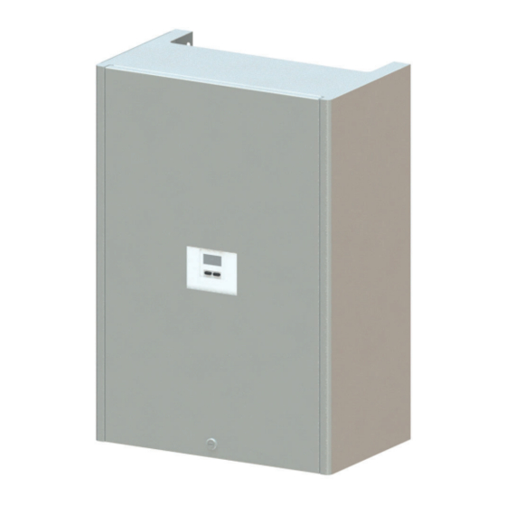
- Page 1 Uponor Combi Port PRO XU Installation and Operation Manual...
-
Page 2: Table Of Contents
................... 12 Mounting station ..............13 Mounting UFH manifold ............13 Troubleshooting ..............28 ........13 Connection single room controller ........... 14 Mounting cabinet cover ............14 Performance curves .............. 30 2 l Uponor Combi Port PRO XU l Installation manual... -
Page 3: Appliance Information
Thermal separation or, preferably, spatial or the components connected to it, disconnect the controller separation is required. from the power supply as instructed. The outlets are also in an inactive state under mains voltage. Uponor Combi Port PRO XU l Installation manual l 3... -
Page 4: Validity Of The Instructions
Service work (assembly, commissioning and maintenance) on the heat interface unit requires specialist knowledge. In general, only authorised specialist tradesmen are allowed to carry out service work on the heat interface unit. 4 l Uponor Combi Port PRO XU l Installation manual... -
Page 5: Specialised Installers
Operating pressure PN10 Min. cold water pressure approx. 2 bar Max. cold water pressure approx. 4 bar Connections Weight approx. 30 kg unit with cover approx. 22 kg unit only Uponor Combi Port PRO XU l Installation manual l 5... -
Page 6: Device And Functional Description
Emerging water from the control holes does not lead to functional loss. However, the PM-controller shall be replaced immedi- ately on the occurrence of leakages in order to avoid water damages. Unauthorized interferences on the PM-controller are not allowed. 6 l Uponor Combi Port PRO XU l Installation manual... -
Page 7: Components And Device Connections
Pressure gauge Temperature sensors Membrane expansion vessel (MAG) Thermostatic heating limiter Note: The illustration shows a sample set-up. Individual modules may vary in appearance. The legend-based numbering is not continuous. Uponor Combi Port PRO XU l Installation manual l 7... -
Page 8: System Example
2 When the connection to the station should be done from the bottom or both, from top and bottom, then the back plate is required. Please consider the installation steps in chapter “Installation”. 8 l Uponor Combi Port PRO XU l Installation manual... - Page 9 UFH manifolds available: Uponor Vario S Manifolds with top meters, 2 to 15 loops Uponor Vario S Manifolds with lock shield valves, 2 to 15 loops The manifolds includes wall brackets. Actuators are adaptable on the return barr. Setting of lock shield valves is described in chapter “Operation”.
- Page 10 Uponor Smatrix Wave Pulse Uponor Smatrix Base PRO Uponor Smatrix is a fully equipped range of components for room Uponor Base Flexiboard is a 230 V control that enables individual temperature control, optionally via radio or wired. The unique auto- room control for 6 or 8 rooms.
-
Page 11: Installation Variances
A B C D E F A B C D CW from riser DHW to apartment Heating supply primary Heating return primary A B C D E F Heating supply secondary Heating return secondary Uponor Combi Port PRO XU l Installation manual l 11... -
Page 12: Installation
Screw down 2 ball valves (right site, heating connections) and close the 2 pipes with caps ¾”. Fix the ball valves down to the connecting pipes. Fix the connecting pipes on the back plate. 12 l Uponor Combi Port PRO XU l Installation manual... -
Page 13: Mounting Station
Vario S manifold to the ball valves on the station. Connection underfloor heating pipes Please consider: Construction and installation of underfloor heating acc EN 1264. Protocol the loop lengths of each loop. SW 24 SW 30 Uponor Combi Port PRO XU l Installation manual l 13... -
Page 14: Connection Single Room Controller
Electrical connection see chapter 4.3 Note Install the Interface unit allways outside the cabinet (wireless connection). Mounting cabinet cover The cover is to be hung with the suspension hooks on the back plate. 14 l Uponor Combi Port PRO XU l Installation manual... -
Page 15: Operation
• Observe the hydraulic diagram as an installation guide. 4.1.3 Sample application: Implementation with a flow rate up to 1 m Uponor Combi Port PRO XU l Installation manual l 15... -
Page 16: Hydraulic Scheme
Smatrix or Flexiboard. 4 Establish equipotential bonding by using a copper equipotential bonding conductor (cross-section at least 6mm ). Connect the earthling clamp to a suitable equipotential bonding rail in the building. 16 l Uponor Combi Port PRO XU l Installation manual... -
Page 17: Installed Parts
/h and an overall length of 110 mm and 3/4" connection can be accomodated. Heat meters Qn = 1,5 with measurement). A sensor pocket for the M10x1 is available for the socket wrench (6 mm). Uponor Combi Port PRO XU l Installation manual l 17... -
Page 18: Dhw Temperature Controller (Twb)
• Reinstall the hand wheel to the set value so that the hand wheel is blocked with the new setting. 5 Install the thermostatic tip. • Screw the valve tip onto the valve The standard setting is changed. 18 l Uponor Combi Port PRO XU l Installation manual... -
Page 19: Thermostatic Heating Limiter
15°C (below the pirmary supply temperature) Example: primary supply 70°C, TTV setting at approx 55°C Please note: • Connection to the capillary tube diameter 6 mm also changes the • Kvs value: 1.55 Uponor Combi Port PRO XU l Installation manual l 19... - Page 20 Q/m³/ h p/kPa Wilo-Yonos PARA RS 4300 /min 15/6, 25/6, 30/6 1~230 V - Rp½, Rp 1, Rp 1¼ 3400 /min 2390 /min /min Q/m³/ h Q/l/s Q/Igpm max. Q/m³/ h 20 l Uponor Combi Port PRO XU l Installation manual...
-
Page 21: Hydraulic Balancing Of Ufh Manifold
Hoeveelheid water Ventielvoorinstelling N° de la pièce N° du circuits de Quantité d’eau Réglage de la vanne Num. locale chauffage Quantità di acqua Tartura della valvola Num. circuito L/min riscaldamento locale Uponor Combi Port PRO XU l Installation manual l 21... -
Page 22: Flush The Primary Heating System
- Assemble the protective cap (hexagon 32 mm) 4.12 Fill/flush and vent Filling loop and flushing set heating and cold water as showed in the picture. Vent the heat interface unit at the ventilation valve 5 . 22 l Uponor Combi Port PRO XU l Installation manual... -
Page 23: Occupant Information
Restrictions are only imposed by the central heating. The heating lines or heat exchangers are permanently maintained at a basic temperature, usually 45°C. this temperature should not be increased. Uponor Combi Port PRO XU l Installation manual l 23... - Page 24 Longer absences after your return, let the hot water run for about 5 minutes. Set the heating to frost protection! Make sure not to close ball-valves A, C and D. 24 l Uponor Combi Port PRO XU l Installation manual...
-
Page 25: Dimensional Drawings
3/4" Euro 13 x 3/4 Euro 1" 3/4" Euro 14 x 3/4 Euro 1" 3/4" Euro 15 x 3/4 Euro 1" 3/4" Euro 16 x 3/4 Euro 1" 3/4" Euro Uponor Combi Port PRO XU l Installation manual l 25... -
Page 26: Cabinet Back Plate
Cabinet back plate Cabinet cover 26 l Uponor Combi Port PRO XU l Installation manual... -
Page 27: Ball Valves On Rail Top 6X
Ball valves on rail top 6x Flushing valve Uponor Combi Port PRO XU l Installation manual l 27... -
Page 28: Troubleshooting
Clean the cold water throttle valve Noise generated via a third route Replace the MS disc, spring and locking ring using a Noise generated in the PM valve replacement kit for PM valves, 3rd route 28 l Uponor Combi Port PRO XU l Installation manual... - Page 29 Check the central heating circuit pump is working and correctly set No hot water and no heating Central strainer is dirty Clean the central strainer Heating system is not working correctly Check the heating system Uponor Combi Port PRO XU l Installation manual l 29...
-
Page 30: Performance Curves
Cold water warming 45 K (10 - 55 °C) Primary heating supply: Primary heating supply: 1200 1200 1100 1100 1000 1000 Taping capacity litre/min Taping capacity litre/min Taping capacity litre/min Taping capacity litre/min 30 l Uponor Combi Port PRO XU l Installation manual... - Page 31 = typ Yonos Para RS 15/6RKA Primary heating demand and return temperatures Cold water warming 50 K (10 - 60 °C) Primary heating supply: 1200 1100 1000 Taping capacity litre/min Taping capacity litre/min Uponor Combi Port PRO XU l Installation manual l 31...
- Page 32 Cold water warming 45 K (10 - 55 °C) Primary heating supply: Primary heating supply: 1200 1200 1100 1100 1000 1000 Taping capacity litre/min Taping capacity litre/min Taping capacity litre/min Taping capacity litre/min 32 l Uponor Combi Port PRO XU l Installation manual...
- Page 33 = typ Yonos Para RS 15/6RKA Primary heating demand and return temperatures Cold water heat up 50 K (10 - 60 °C) Primary heating supply: 1200 1100 1000 Taping capacity litre/min Taping capacity litre/min Uponor Combi Port PRO XU l Installation manual l 33...
- Page 34 34 l Uponor Combi Port PRO XU l Installation manual...
- Page 35 Uponor Combi Port PRO XU l Installation manual l 35...
- Page 36 Uponor GmbH Industriestraße 56 D-97437 Hassfurt, Germany 1096066 01.2020 www.uponor.com Production Uponor/KeL...
Need help?
Do you have a question about the KaMo Combi Port PRO XU and is the answer not in the manual?
Questions and answers