Olympus DSX1000 Instructions Manual
Digital microscope hardware
Hide thumbs
Also See for DSX1000:
- Quick reference manual (16 pages) ,
- Quick reference manual (16 pages)
Table of Contents
Advertisement
Instructions
DSX1000
Digital microscope
Hardware
Notes
This instruction manual is for the Olympus Digital Microscope.
To ensure safety, obtain optimum performance and to familiarize yourself fully with the use of
this product, we recommend that you study this manual thoroughly before operating this
product, and always keep this manual at hand when operating this product.
Retain this instruction manual in an easily accessible place near the work desk for future
reference.
For details of products included in the configuration of this system, see pages from
14
to
18
.
Optical Microscope and Accessory
Downloaded from
ManualsNet.com
search engine
Advertisement
Table of Contents

Related Manuals for Olympus DSX1000


Summary of Contents for Olympus DSX1000
- Page 1 Digital microscope Hardware Notes This instruction manual is for the Olympus Digital Microscope. To ensure safety, obtain optimum performance and to familiarize yourself fully with the use of this product, we recommend that you study this manual thoroughly before operating this product, and always keep this manual at hand when operating this product.
- Page 2 In accordance with European Directive on Waste Electrical and Electronic Equipment, this symbol indicates that the product must not be disposed of as unsorted municipal waste, but should be collected separately. Refer to your local Olympus distributor in EU for return and/or collection systems available in your country.
-
Page 3: Table Of Contents
DSX1000 Contents 1. Concept of this instruction manual 1.1 Applicable user of this instruction manual 1.2 Configuration of instruction manuals 1.3 How to read this instruction manual 2. Product concept 2.1 Product outline 2.2 Intended use 2.3 Trademark 3. Safety precautions 3.1 Transportation... - Page 4 8.11 Installation and Uninstallation of the application 8.12 Connection of the USB license key 8.13 Packaging of units 9. Proper selection of the power supply cord Appendix: Units attached by Olympus Attaching the PCIe interface board Downloaded from ManualsNet.com search engine...
-
Page 5: Concept Of This Instruction Manual
DSX1000 Concept of this instruction manual This instruction manual describes the contents related to the whole DSX1000 system. 1.1 Applicable user of this instruction manual This instruction manual applies to users who use this product according to "Intended use" (3 page) and Olympus distributors. -
Page 6: How To Read This Instruction Manual
DSX1000 1.3 How to read this instruction manual This instruction manual is created as follows. Title in first layer Title in second layer Title in third layer Operating procedure ... indicates the operating procedure and ... indicates the portion you operate. -
Page 7: Product Concept
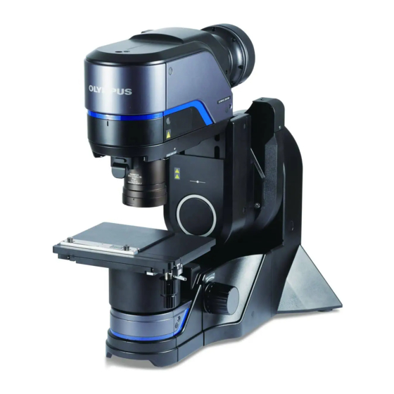
DSX1000 Product concept 2.1 Product outline This product is a next generation digital microscope equipped with a variety of observation methods and image processing functions, covering a wider range of magnification with just one system. This product eliminates the annoying operations in existing optical microscopes or digital microscopes, and offers "Smart Analysis"... -
Page 8: Safety Precautions
Always use the product according to this instruction manual. 3.1 Transportation It is recommended to request Olympus for transporting this product or assembling units. CAUTION Be careful not to drop this product while transporting it. If the product is dropped, there is a risk of injuring your feet or other body parts. - Page 9 If you need to package this product, such as to ship to the distant location, you need to use the dedicated package box. In this case, be sure to contact Olympus for assistance. If you transport and install this system overseas by yourself without prior notice to Olympus, the services in the destination country will not be provided.
-
Page 10: Installation And Uninstallation Of The Application
Before connecting/disconnecting cables, turn off all main switches of the system and unplug the power cord from the outlet. 3.4 Electric safety Always use the power cord provided by Olympus CAUTION 3. Safety precautions 3.2 Installation and Uninstallation of the application Downloaded from ManualsNet.com... -
Page 11: Prevention Of Eye Injury
DSX1000 If the proper power cord is not used, the electric safety and the EMC (Electro-Magnetic Compatibility) performance of the product cannot be assured. If no power cord is provided, please select the proper power cord by referring to the section "Proper selection of the power cord" at the end of this instruction manual. -
Page 12: Prevention Of Injury
DSX1000 damage to your eyes. 3.6 Prevention of injury CAUTION Do not put your hands in the lower part of the microscope frame. Your hands or fingers could be pinched. Be careful not to pinch your hands in the microscope frame or cut your hands with the edge of the system. -
Page 13: Safety Symbols
DSX1000 3.7 Safety symbols The following symbols are placed on this product. Study the meaning of the symbol and always use the product in the safest possible manner. Symbol Meaning Indicates a non-specific general hazard. Follow the description given after this symbol or in the instruction manual. - Page 14 DSX1000 Control box DSX10-CB Stage mount Bottom of motorized stage PCIe interface board Label position Safety label Instructions in the instruction manual "Prevention of electric shock" (6 page) "Electric safety" (6 page) "Prevention of electric shock" (6 page) "Electric safety" (6 page) "Prevention of electric shock"...
-
Page 15: Handling Precautions
Olympus, contact Olympus. It is recommended to change your password regularly as a security measure. Olympus does not support your connecting to a LAN. If you would like to connect this product to a LAN, you need to connect it yourself. -
Page 16: Detaching The Transport Locks
DSX1000 For procedures to backup and restore the controller (Windows 10 system), see the documents in the following directory or URL. C:\Program Files\OLYMPUS\DSX-BSW\Common\Help Win10_SystemBackUp_Restoration_Procedures_E.pdf https://www.olympus-ims.com/resources/manuals/ (Search for "System backup and restoration of Windows10" in the keyword search field on the Web page.) If the processing speed becomes slower due to the higher load to the controller, the message appears and you cannot use the [Large lower coarsely] button on the [Focus] tab. -
Page 17: General
Do not repair the system by yourself. If you repair or move this system yourself, Olympus shall not be liable for any consequence even if the product malfunctions or is damaged. Also, even during the guarantee period, the free-repair may not be applied in some cases. -
Page 18: Specifications
DSX1000 Specifications 5.1 Hardware Function Unit Name Specifications Zoom head Universal zoom head Observation method DSX10-UZH Brightfield observation Darkfield observation Simultaneous brightfield/darkfield observation Differential interference contrast observation Simple polarization observation Oblique observation Depth of focus adjustment Focusing part Z movable range: 100.5 mm Drive resolution: 0.01 μm... - Page 19 DSX1000 Communication with controller PC Upright frame Focusing: DSX10-UF Coarse/fine coaxial focusing knob Stroke: 50 mm Equipped with function to adjust rotation tension Motorized control unit: Control of zoom head DSX10-UZH / DSX10-SZH Control of LED transmitted light illuminator DSX10-ILT...
- Page 20 DSX1000 DSX10-SXLOB10X: 0 to ± 5.2 Diffused illumination adapter for DSX10- WD (mm) 1.7 to 11.7 SXLOB3X Tiltable angle (°) DSX10-DIAD3X ±5.1 to ±31.6 Polarized illumination adapter for DSX10- Adjustable angle: 90° Equipped with scale to reproduce the position SXLOB...
-
Page 21: Dimension And Weight
DSX1000 Experiment total assist software *4 Media type: DVD OLS51-S-ETA Storage case Objective lens case Three pieces of lens attachments with objectives DSX10-LC attached can be stored. Calibration sample Calibration sample P50 (50 µm × 200) DSX-CALS-HR P10 (10 µm × 360) P3 (3 µm ×... -
Page 22: Loading Capacity Of Stage
DSX1000 Super long working distance objective lens 10X 75.4(W) x 172.5(D) x 105.1(H) DSX10-SXLOB10X Long working distance objective lens 3X 45(H) x 44.9(D) DSX10-XLOB3X Long working distance objective lens 10X 44(H) x 45(D) DSX10-XLOB10X Long working distance objective lens 20X 44(H) x 54.5(D) -
Page 23: Rating
DSX1000 XLOB Series 0 to 115 mm UIS2 Series 0 to 145 mm Eucentric observation (common objective) 0 to 50 mm 5.5 Rating 5.5.1 Combination with DSX10-UF / DSX10-TF 100-120 V, 220-240 V 1.1/0.54 A 50/60 Hz 5.5.2 Combination with DSX10-CB 100-120 V, 220-240 V 0.93/0.45 A... - Page 24 DSX1000 FCC: In compliance with Part15 Class A Environmental RoHS (Europe only) In compliance with the rules of environment-related substance management for Olympus group standards product 5. Specifications 5.8 Measures for safety and environmental law Downloaded from ManualsNet.com search engine...
-
Page 25: List Of Combinable Units
DSX1000 List of combinable units 6.1 Correspondence table of units and observation methods Simultaneous Differential Simple F.O.V. W.D. Total Brightfield Darkfield brightfield/ interference Objective name Oblique polarization (mm) magnification (mm) darkfield contrast Super long working distance objective lens series DSX10-SXLOB1X 0.03 51.7... -
Page 26: Combination Of Units
DSX1000 6.2 Combination of units Stage Stage holder and stage plate Rotatable motorized XY stage Black-and-white plate *1 DSX10-RMTS High-precision plate *1 *1: Provided with stage XY motorized stage DSX10-MTS Manual stage Wafer holder plate Rotating wafer holder U-SIC4R2 U-WHP2... -
Page 27: Maintenance And Storage
DSX1000 Maintenance and Storage 7.1 Cleaning of each part Lens and filter Do not leave stains or fingerprints on the lenses or filters. If they get dirty, blow away dust with a commercially available blower and gently wipe the lens or filter with a piece of cleaning paper (or washed-out clean gauze). -
Page 28: Cautions After Use
(except consumables) 7.4 Replacement of the lens attachment If the clicking of the lens attachment becomes weak, contact Olympus for assistance. Guide for replacement: Approx. 3 to 5 years from the start of use. 7. Maintenance and Storage 7.2 Cautions after use... -
Page 29: Assembly
DSX1000 Assembly 8.1 Assembly diagram It is recommended to request Olympus to assemble this product to secure its performance. For installation, remove dirt or dust from the attaching portions and be careful not to scratch them. NOTE 8.3 Attachment of the zoom head 8.6 Attachment of the lens attachment... - Page 30 DSX1000 Attachment flow chart Unpack each unit. Read the insertion provided with the product as well. Install the microscope frame. Detach the transport locks of microscope frame. (30 page) When the motorized stage is combined: When the manual stage is combined: Connect the camera cable.
- Page 31 DSX1000 Detachment flow chart Attach the transport locks of the zoom head. page)(Step to Step Detach the transport locks of zoom head. Close the application and shutdown Windows. Turn OFF the power switch. Detach the optional unit Detach the polarized illumination adapter. (42 page)
- Page 32 DSX1000 Setup the controller PC Unpack the controller PC. Attach the PCIe I/F board. Performed by Olympus Connect the cables. (44 page) Set BIOS / OS. Refer to "BIOS/OS settings of PC" provided with DSX10-BSW. Install the device driver. (48 page) Install the basic software DSX10-BSW Refer to "Installation and Uninstallation of DSX10-BSW"...
- Page 33 DSX1000 Detach the controller PC. Disconnect the USB license key. (49 page) Disconnect the cables. (44 page) Pack the controller PC. For handling the controller PC that combines the PCIe IF board, refer "Attaching the PCIe interface board" (53 page).
-
Page 34: Detachment/Attachment Of Transport Locks Of Microscope Frame
DSX1000 8.2 Detachment/attachment of transport locks of microscope frame If you rotate the focusing knob without detaching the transport locks, the product could be damaged. Be NOTE sure to detach them. As the transport locks will be used for transporting the system next time, keep them in a safe place. -
Page 35: Attachment/Detachment Of The Zoom Head
DSX1000 8.3 Attachment/detachment of the zoom head Attach or detach the zoom head according to this section. If you attach or detach the zoom head in CAUTION incorrect procedures, the product may be damaged due to the influence of static electricity. - Page 36 DSX1000 While pushing the zoom head to the microscope frame, rotate the zoom head counterclockwise until it stops, and tighten the clamping screws (3 positions) provided with the zoom head using the Allen wrench provided with the zoom head. Insert the tip of the long side of Allen wrench into the clamping screw and tighten it temporarily. And then, insert the tip of the short side of Allen wrench into the clamping screw and tighten it completely.
- Page 37 DSX1000 Close the application and shutdown Windows. Turn OFF the power switch on the back of the tilting frame DSX10-TF or the upright frame DSX10-UF. If you are using the control box DSX10-CB, turn OFF the power switch on the back of the control box.
-
Page 38: Attachment/Detachment Of The Stage
DSX1000 8.4 Attachment/detachment of the stage 8.4.1 Attaching the motorized stage (DSX10-RMTS or DSX10-MTS) Before attaching or detaching the stage, turn OFF the main switch. NOTE As the stage is connected to the microscope frame electrically, if you attach or detach the stage while the power is ON, the product could be damaged. - Page 39 DSX1000 Detach the transport locks (2 positions) using the Allen wrench provided with the stage. If you move the stage without detaching the transport locks, the product could be damaged. Be sure to NOTE detach them. As the transport locks will be used for transporting the system next time, keep them in a safe place.
- Page 40 DSX1000 Place either the high-precision plate or the black-and-white plate on the stage. In the case of the high-precision plate, place the obliquely-cut surface facing down. Attach the rubber caps (4 pcs.) provided with the stage to the holes at four corners of the stage.
- Page 41 DSX1000 8.4.2 Attaching/detaching the manual stage adapter (DSX10-MSTAD) Rotate the focusing knob to raise the stage mount to the upper limit position. Detach the clamping screws (6 positions) using the Allen wrench provided with the manual stage adapter DSX10- MSTAD and detach the base of the stage.
- Page 42 DSX1000 Tighten the provided clamping screws (2 positions) from the back side using the Allen wrench to secure the manual stage adapter. Align the screw holes (inside 3 positions) of the manual stage adapter with the mount holes (3 positions) of the manual stage mount, and tighten the provided clamping screws to secure the manual stage adapter.
- Page 43 DSX1000 If you tighten the clamping knob too firmly, the stage floats up and the level cannot be secured. Tighten the NOTE clamping knob appropriately. Detaching the manual stage (U-SIC4R2) To detach the manual stage, perform the procedure described above in reverse order.
-
Page 44: Attachment/Detachment Of The Objective
DSX1000 To detach the wafer holder, perform the procedure described above in reverse order. 8.5 Attachment/detachment of the objective Place the lens attachment on a soft cloth, etc. on the table. The lubricant is applied to the portion where the lens attachment and the zoom head are connected. If you place the lens attachment on the desk directly, the desk may get dirty. -
Page 45: Attachment/Detachment Of The Lens Attachment
DSX1000 8.6 Attachment/detachment of the lens attachment Hold the lens attachment securely with both hands. As the objective lens is heavy, it could be dropped to CAUTION cause you injury. Depending on the objective, there are lens attachments that may not be attached if the zoom head is not placed at the objective exchange position. -
Page 46: Attachment/Detachment Of The Polarized Illumination Adapter
DSX1000 8.7 Attachment/detachment of the polarized illumination adapter The polarized illumination adapter can be attached only to the super long working distance objective lens (DSX10- SXLOB1X, DSX10-SXLOB3X or DSX10-SXLOB10X). Attaching the polarized illumination adapter Align the groove of the super long working distance objective lens with the protrusion of the polarized illumination adapter DSX10-POAD. -
Page 47: Attachment/Detachment Of The Diffused Illumination Adapter
DSX1000 8.8 Attachment/detachment of the diffused illumination adapter The diffused illumination adapter can be attached only to the super long working distance objective lens (DSX10- SXLOB1X, DSX10-SXLOB3X or DSX10-SXLOB10X). Attaching the diffused illumination adapter Align the groove of the super long working distance objective lens with the protrusion of the diffused illumination adapter (DSX10-DIAD3X or DSX10-DIAD1X10X). -
Page 48: Attachment/Detachment Of The Led Transmitted Light Illuminator (Optional)
Cables and cords are vulnerable to bend or twist. Do not apply excessive force to them. Always connect the units specified by Olympus to each connector. Make sure of the correct orientation of the connector, and insert it. Tighten the clamping screws if provided. - Page 49 DSX1000 Connecting with the tilting frame DSX10-TF or the upright frame DSX10-UF Units to connect: Controller PC (Serial port) Zoom head DSX10-UZH/DSX10-SZH LED transmitted light illuminator DSX10-ILT Console DSX10-CSL The cable can be connected to either [OUT1] or [OUT2] on the back of the microscope frame.
- Page 50 DSX1000 8.10.1 Routing the cables Route the cables giving plenty of length to allow the zoom head or the stage to move without tension. NOTE Particularly, the camera cable of the zoom head must be routed so as not to be caught in the zoom head in all stroke range.
- Page 51 Bundle the camera cable and the RS232C cable with the Velcro tape provided with the zoom head. 8.10.2 Connecting with the control box (Optional) If you want to enable the functions of the digital microscope using the microscope frame other than the DSX1000 series microscope frame (DSX10-TF or DSX10-UF), connect the control box DSX10-CB.
-
Page 52: Installation And Uninstallation Of The Application
Attach the PCIe interface board before installing the device driver. The PCIe interface board must be attached by Olympus. If you attach the PCIe interface board, the system operation is not guaranteed. Insert the installation DVD of the basic software DSX10-BSW in the DVD drive of the controller PC. -
Page 53: Connection Of The Usb License Key
Display a list of programs. Click the [Start] button, and select [Settings] - [Apps] - [Apps & features]. Select the [Windows driver pacage OLYMPUS CORPORATION (MALPCI64) MALPCI] from the program list and click the [Uninstall] button. Click the [Uninstall] button again. - Page 54 DSX1000 When you package the microscope frame, put the microscope frame in the package box, and then cover it with the pad in the appropriate direction. Cover the microscope frame with the pad in the direction shown in the picture below.
-
Page 55: Proper Selection Of The Power Supply Cord
If no power supply cord is provided, please select the proper power supply cord for the equipment by referring to “Specifications” and “Certified Cord” below: Caution : In case you use a non-approved power supply cord for Olympus products, Olympus can no longer warrant the electrical safety of the equipment. - Page 56 DSX1000 Table 2 HAR flexible cord Approval organizations and cordage harmonization marking methods. Alternative marking utilizing Printed or embossed black-red-yellow thread (Length harmonization marking (May be Approval organization of color section in mm) located on jacket or insulation of internal wiring)
-
Page 57: Appendix: Units Attached By Olympus
DSX1000 Appendix: Units attached by Olympus The units described in this section must be assembled or adjusted by Olympus. If you assemble or adjust the following units, the system operation is not guaranteed. Attaching the PCIe interface board While using this product, the PCIe interface board becomes very hot. When removing the PCIe interface CAUTION board, turn OFF the power of the controller PC and wait for a while before removing it. - Page 58 PCIe slot. Open the cover of the controller PC. Remove the slot cover of an unused PCIe slot on the motherboard. Appendix: Units attached by Olympus Attaching the PCIe interface board Downloaded from ManualsNet.com...
- Page 59 PC such as fan, etc. To detach the PCIe interface board, perform the procedure described above in reverse order. Appendix: Units attached by Olympus Attaching the PCIe interface board Downloaded from ManualsNet.com...
- Page 60 AX9336 06 Issued in September, 2021 Downloaded from ManualsNet.com search engine...
Need help?
Do you have a question about the DSX1000 and is the answer not in the manual?
Questions and answers