
Related Manuals for PCE Instruments PCE-DFG 500 Series


Summary of Contents for PCE Instruments PCE-DFG 500 Series
- Page 1 Manuale d’istruzioni Dinamometro serie PCE-DFG 500 Versione 1.1 Version 1.1 © PCE Instruments...
- Page 2 China Hong Kong Pingce (Shenzhen) Technology Ltd. PCE Instruments HK Ltd. West 5H1,5th Floor,1st Building Unit 1601, 16/F., Malaysia Building Shenhua Industrial Park, 50 Gloucester Road Meihua Road,Futian District Wanchai Shenzhen City / China...
-
Page 3: Table Of Contents
Indice / Contents Italiano Sicurezza ..............................4 Specifiche tecniche ............................ 4 Panoramica del dispositivo ........................5 Istruzioni ..............................6 Menu ................................8 Interfaccia esterna.............................11 Manutenzione e calibrazione ........................12 Smaltimento ............................. 12 English Safety notes ............................. 14 Specifications ............................14 System description ........................... -
Page 4: Italiano
- La mancata osservanza delle presenti istruzioni possono comportare guasti al dispositivo e lesioni alll’utilizzatore. Il presente manuale di istruzione è stato pubblicato da PCE Instruments senza nessun tipo di garanzia. Per consultare le condizioni generali di garanzia, rimandiamo al capitolo dedicato ai nostri Termini e condizioni. -
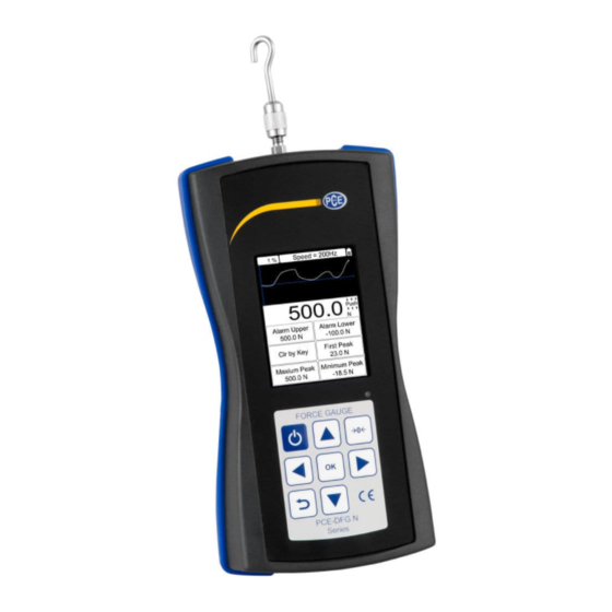
Page 5: Panoramica Del Dispositivo
Aggiornamento del display 10-volte / Sec. Memoria 1000 Dati Alimentazione Batteria ricaricabile Ni-MH Durata della batteria ca. 16 ore di funzionamento continuo con batteria completamente cariche Caricabatteria / Alimentatore Caricabatteria universale USB/BM, Ingresso: 110 Q 240 VAC Uscite USB, RS232, Uscite setpoint Condizioni Condizioni operative: -10 Q 40 °C;... -
Page 6: Istruzioni
Tastiera On / Off: Tenere premuto questo pulsante per 2 secondi per accendere o spegnere il dispositivo. Durante la misurazione: Stampa i valori correnti o i dati salvati in base alle impostazioni del pulsante. (vedi Impostazioni dei pulsanti). Nei menu: Indietro o Esci. Durante la misurazione: per accedere all'area del menu. - Page 7 4. 5 Limiti di tolleranza Si possono impostare i limiti di tolleranza pass/fail. S e si at ti v a l’ al l arme e si im pos t a un lim it e v ali do, si v is ual i zza l’i c ona per i v al ori ent ro i limi ti , l’icona al di sotto del limite minimo e l’icona per il valori che superano il limite massimo.
-
Page 8: Menu
Menu Struttura del menu Il dinamometro ha un menu multi-livello. Dalla schermata iniziale, premere il tasto MENU / ENTER per accedere al menu. Test Setup Unità Gruppo Tolleranza Mode Test Peak Time Allarme Memoria Modalità di memorizzazione Sfoglia tutto Sfoglia selez. Elimina selez. - Page 9 5.2.1 Unità L'unità di misura può essere selezionata in questo menu. Le unità dipendono dal campo di misura. Le unità disponibili sono: N, gf, kgf, lbf e ozf. 5.2.2 Gruppo Se è necessario misurare vari campioni, questi possono essere suddivisi in gruppi tra 01 e 99 5.2.3 Tolleranza Nel menu di tolleranza, possono essere impostati i limiti massimo e minimo per il pass/fail.
- Page 10 5.4.2 Impostazioni della stampante Stampa ultimo dato: Per stampare l’ultimo valore misurato. Stampa dato selezionato: Per stampare i valori selezionati. Stampa tutti i dati: Per stampare tutti i valori di misura. Sistema 5.5.1 Modalità Display L'allineamento dello schermo LCD può essere regolato automaticamente o manualmente. Si può scegliere tra Auto, Normal e revers (180 gradi).
-
Page 11: Interfaccia Esterna
Interfaccia esterna Interfaccia multifunzione MD8 Descrizione Trasmettitore RS232 (Transmit - TX) Ricevitore RS232 (Ricezione - Rx) RS232 - terra Uscita allarme A + Non utilizzato Uscita allarme Com - Uscita allarme B + Non utilizzato Interfaccia USB La porta USB viene utilizzata per trasmettere dati ad un PC, oltre che per la ricarica. Collegare il cavo USB al caricabatterie per la ricarica. -
Page 12: Manutenzione E Calibrazione
Uscita di allarme: Il dispositivo è dotato di due uscite di allarme. È possibile connettersi ad altri dispositivi simili (banco di prova, modulo logico o dispositivi di allarme). Tensione massima consentita Pin 7 - Pin 6, Pin 4 - Pin 6: 35 V Pin 6 - Pin 7, Pin 6 - Pin 4: 6 V Manutenzione e calibrazione Ricarica... - Page 13 IT - 13...
-
Page 14: English
Please read this manual carefully and completely before you use the device for the first time. The device may only be used by qualified personnel and repaired by PCE Instruments personnel. There is no warranty of damages or injuries caused by non-observance of the manual. -
Page 15: System Description
Charger / adaptor universal USB/BM charger, input: 110 ... 240 VAC Outputs USB, RS232, setpoint output Environmental conditions Operating conditions: -10 Q 40 °C; 20 Q 80 % RH Storage conditions: -20 Q +50 °C; 5 Q 95 % RH Dimensions 184.3 x 93.9 x 35.4 mm 1.05 kg (2.31 lb) -
Page 16: Instructions
Keypad Power: Press and hold for 2 seconds to power on or off. During measurement: Prints the current force value or stores data, depending on the key setting (see Key Setting). In menus: Back or exit. During measurement: Enters the menus. In menus: Select or enter. - Page 17 4. 5 Tolerance limits The tolerance limits can also be set for good/not good measurement. If you activate the alarm and set up a valid limit, the icon will be displayed for values within the limit, the icon for values below the lower limit and the icon for values that exceed the upper limit.
-
Page 18: Menus
Menus Menu structure The force gauge has a multi-level menu interface. From the home screen, press MENU/ENTER to enter the menu. Test Setup Unit Group Tolerance Test Mode Peak Time Alarm Memory Storage Mode Browse all Browse selected Delete selected Delete all Printing Print recent... - Page 19 5.2.2 Group When several test samples need to be measured, the samples can be divided into groups between 01 and 99. 5.2.3 Tolerance In the Tolerance menu, the upper and lower limits for good/not good measurement can be set up. The upper limit value must be higher than the lower limit and both limit values cannot exceed 110 % of the rated capacity.
-
Page 20: External Interface
System 5.6.1 Display Mode The direction of the LC display can be adapted automatically or manually. You can select Automatic, Obverse or Reverse (180 °). 5.6.2 Power Off The force gauge can turn the power off automatically after a certain time interval without operation. 5 minutes is the default setting. - Page 21 The force gauge has two external ports: a USB port and an MD8 port. USB port The USB port is used to transmit data to a PC, as well as for recharging. Connect the USB cable to the charger for recharging. Multifunctional port The MD8 port is a multifunctional port which includes an RS232 interface to connect to a printer or computer, as well as two alarm outputs.
-
Page 22: Maintenance And Calibration
In order to comply with the EU directive 2012/19/EU we take our devices back. We either re-use them or give them to a recycling company which disposes of the devices in line with law. If you have any questions, please contact PCE Instruments. EN - 22... - Page 23 EN - 23...
- Page 24 Specifications are subject to change without notice.
Need help?
Do you have a question about the PCE-DFG 500 Series and is the answer not in the manual?
Questions and answers