Table of Contents
Advertisement
Quick Links
Advertisement
Table of Contents

Related Manuals for Vent-Axia MX 10/10


Summary of Contents for Vent-Axia MX 10/10
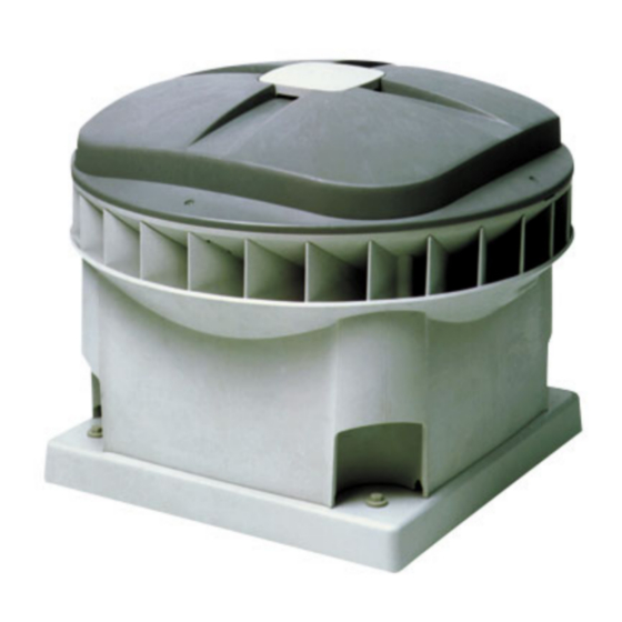
- Page 1 MX type roof extract fan instructions for use ®...
-
Page 2: Table Of Contents
® Table of Contents ………………………………………page 3 Foreword 11. Malfunctions 11.1 Malfunction tables …………………………page 22-24 …………………page 25 Guarantee and liability 11.2 Replacement of components …………………………page 3 ………………………………………page 26 2.1 Guarantee conditions 11.3 Logbook 2.2 Liability ………………………………………page 3 …………………page 27 12. EC declaration of conformity Safety ……………………page 4 3.1 General safety regulations... -
Page 3: Foreword
Kingdom. For details of guarantee outside the United Kingdom following types: contact your local supplier. MX 10/10 Vent-Axia guarantees its products for two years from the date of MX 20/20 purchase against faulty material or workmanship. In the event of any MX 30/10... -
Page 4: Safety
® 3. Safety 3.1 General safety regulations • Always comply with the safety regulations and instructions given in this manual. • Make sure that (parts of) the fan not (yet) anchored and tools cannot fall off the roof and cause damage or personal injury. •... -
Page 5: Technical Data
® 4. Technical data MX 10/10 ∆ Pst Pa (N/m Current Power Noise level Speed consumption consumption deliv suctionsuction*cos. = MX ϕ W el dB(A) dB(A) dB(A) 1800 1800 0,76 0,99 1600 1600 0,55 0,99 max. power cons. 1400 0,39... -
Page 6: Dimensioned Drawings
® 4. Technical data 4.2 Dimensioned drawings øD A (inw.) ø10(4x) type type of fan of acc* A MX 10 330 460 330 575 60 473 44 196 MX 20 450 580 450 708 60 540 48 241 MX 30 535 665 535 863 60 601 64 302... -
Page 7: Speed Control
® 5. Speed control Various regulators can be fitted in order to regulate the speed. A 5.4 RSC servo contact distinction is made between regulation of one fan or regulation of a The servo contact can be used for the parallel switching of another number of fans at the same time. -
Page 8: Communication
• required capacity and limitations of minimum and maximum via a modem or other equipment, for this purpose. For more capacity; information, refer to the ‘VENT-AXIA Maintenance – Software – • current speed; Networks – Communication Manual’, available from VENT-AXIA. -
Page 9: Installation
® 7. Installation 7.1 Installation conditions 7.4 Installation • The MX must be installed according to the general and locally applicable safety and installation regulations. General • The MX must be fitted in such a manner that there is no risk of •... -
Page 10: Electrical Connection
® 8. Electrical connection 8.1 Controls connection strip The connection strip of the controls is shown below. sensor connection 0-10 V controls input Failure contact make KL2B KL5A KL3B PE 1 +15V +15V 18 V E U3 10 V E Ö... -
Page 11: Relationship Between Speed And
® 8.3 Relationship between speed and current at 0-10V controls Adjustment example input If you wish to adjust an MX 20/10 to two speeds using the SAG 0-2: When connecting regulators, the speed of the MX is controlled by 750 rpm and 1000 rpm, follow the example below. varying the voltage at the 0-10 V controls input. -
Page 12: Wiring Diagrams
® 8. Electrical connection The fan is connected in accordance with the applicable diagram. A number of diagrams may be simultaneously applicable. The fan is class 1 and must be earthed 8.4 Wiring diagrams MX (standard) wiring diagram diagram 1 KL 2B KL 3B Motor connection... - Page 13 ® SAG 0-2 / SAG 0-5 / SAG 0-M wiring diagram diagram 2 +10V soll Motor connection KL 2B KL 3B 10 V E soll GND 18 V E ist GND Ö KL 4 An GND KL 3a KL 2A KL 1 remove these links VG 31 wiring diagram...
- Page 14 ® 8. Electrical connection DNG 31 wiring diagram diagram 4 3 X 0,75 mm2 Max. 31 MXs R1 = speed setting potentio-meter = 1 R2 = speed setting potentio-meter = 2 DNG 31 KL 3B KL 2B Motor connection PE 1 18 V E 10 V E Ö...
- Page 15 ® LTG wiring diagram diagram 6 4 x 0,75 mm R=upper temperature setting potentio-meter R7=band width setting potentio-meter Motor connection KL2B KL3B 18V E 10V Esoll Ö KL2A KL3A remove these links Heating Cooling temperature setting 20°C temperature setting 20°C band width 5°C band width 5°C Jumpers (removable link) in 4 positions shown below...
- Page 16 ® 8. Electrical connection diagram 7 Wiring diagram for MX in network GROUND A maximum 31 MXs Shielding R=120 Ohm twisted pair options: A – communication via telephone/modem (9 pins - 25 pins) B – communication with PC (9 pins -9 pins) diagram 8 Wiring diagram for MX in network with modem communication diagram 9...
-
Page 17: Adjustment
® 9. Adjustment 9.1 Summary of MX settings Adjust the MX settings and any control equipment according to the applicable column. The MX is pre-set to the given values. Do not change these values unless absolutely necessary. At [...] fill in the value set by you. Standard: DNG 31 SAG 0 –... -
Page 18: Mx Network: Addressing, Settings And Copying Of Settings
® 9. Adjustment 9.2 MX network: addressing, settings and copying of settings If more than one MX is connected (see diagrams 8 + 9), each MX must have its own address. Addressing 1. Make a (roof) summary of all fans, divide the fans into groups of a maximum of 31 and note an address number and group number by each fan. -
Page 19: Control Of Air Volume
® 9. Adjustment The external resistance can be determined by: 9.3 Control of air volume • measuring the external resistance in the mounting curb; The air volume is determined by the speed of the impeller and the external resistance in the mounting curb, see the graph on page 5. The air volume can now be determined. -
Page 20: Measuring Report
® 9. Adjustment 9.5 Measuring report Type of fan Group / address / Set point Pressure set at ..Pa Net: Room: Kitchen Kitchen Bathroom Toilet …… …… Type of valve or extractor hood: Required air delivery high: in l/s or m A = Setting of the valve or extractor hood Q = Air volume in l/s or m * Delete that which is not applicable. -
Page 21: Inspection And Maintenance
® 10. Inspection and maintenance Exploded view... -
Page 22: Malfunction Tables
® 10. Inspection and maintenance / 11. Malfunctions 10.1 Inspection and maintenance 11.1 Malfunction tables The fan must be inspected once every two years. This depends on the Two malfunction tables have been included below. degree of pollution of the air. More frequent inspection is required in The first table is for identification of a malfunction in an MX. - Page 24 ® 11. Malfunctions Carry out Check to be carried out. If no, the malfunction SAG 0-2 LTG SAG check of: If yes, go to the next line is in the : SAG 0-5 or LTG + DNG 31 SAG 0-M VG 31 VG 31 or DNG 31...
-
Page 25: Replacement Of Components
® 11.2 Replacement of components Controls 1. Remove the fan cover (2). Always apply the valid safety regulations and instructions. 2. Connect a VU manual unit onto the sub D9 connector. • Make sure that (parts of) the fan not (yet) anchored and tools 3. -
Page 26: Logbook
® 11. Malfunctions 11.3 Logbook Fill in the work carried out here: installation, maintenance and malfunctions. Date Assignment no. Name Company Complaint/assignment Solution/Details... - Page 27 ®...
- Page 28 ® MX service parts Component Number MX 10/10 MX 20/10 MX 30/10 MX 30/20 Housing 448000010 448000020 448000030 448000030 Fan cover 448000110 448000120 448000130 448000130 Air cap 448000200 448000200 448000200 448000200 Operating switch 660030040 660030040 660030040 660030040 Frame 348000010 348000020...
- Page 29 Check the underpressure behind the valve furthest from the fan. This must be minimum 50 Pa. Draw up a measuring report. Set any external regulators back to the correct position For further information, see: J.E. VENT-AXIA Ventilation systems Residential Information, ‘Adjustment instructions’ tab sheet.
-
Page 30: Ec Declaration Of Conformity
® 12. EC statement J.E. Stork Ventilatoren b.v. P.o. box 621 8000 AP Zwolle-NL Commercial Register Zwolle 22293 EU-declaration of conformity Machine description MX10/10; MX20/20; MX30/10; MX30/20 EU-Type examination : - Not applicable - Number - Name of notified body - Address Conforms the following directives : - Machinery Directive (98/37/EC) - Page 31 ®...
- Page 32 Vent-Axia guarantees its products for two years from date of purchase against faulty material or workmanship. In the event of any part being found to be defective, the product will be repaired, or at the Company’s option replaced, without charge, provided that the product:- ...
Need help?
Do you have a question about the MX 10/10 and is the answer not in the manual?
Questions and answers