Advertisement
Lo-Carbon
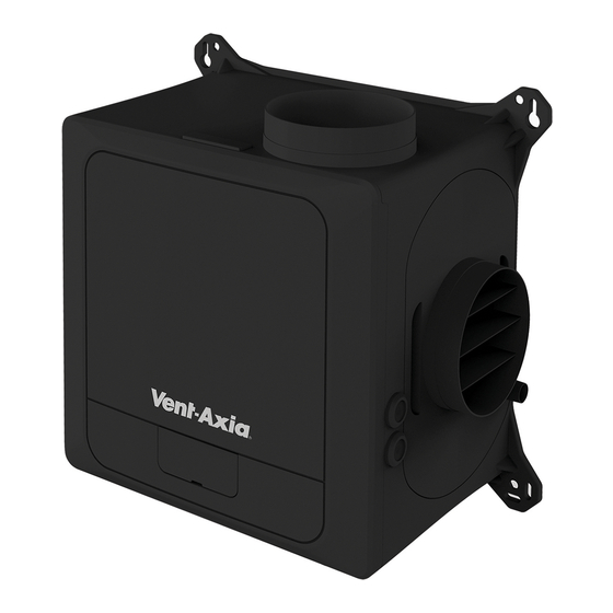
MVDC & SENTINEL
MULTIVENT
RANGE
VENTILATION SYSTEMS
Installation and Wiring Instructions
220-240V~50Hz
ORIGINAL ENGLISH MANUAL.
PLEASE KEEP THIS MANUAL AND READ IN CONJUNCTION WITH THE ILLUSTRATIONS.
DOWNLOAD THE APP HERE:
Stock Ref. N°
MVDC-MS
437634C
MVDC-MSH
443298B
MVDC-MSH UniFlex
498502
SMV-H
445655B
SMV-HX
495360
SMV-HX
CO²
495361
SMV PLUS-H
407849A
SMV PLUS-HX
495362
SMV PLUS-HX
CO²
495363
SMV PLUS-H
496186
(Ventair)
X-Units have wireless controls and
Bluetooth capability.
IPX2
Advertisement
Table of Contents

Related Manuals for Vent-Axia MVDC-MSH UniFlex


Summary of Contents for Vent-Axia MVDC-MSH UniFlex
- Page 1 Lo-Carbon MVDC & SENTINEL MULTIVENT RANGE VENTILATION SYSTEMS Installation and Wiring Instructions Stock Ref. N° MVDC-MS 437634C MVDC-MSH 443298B MVDC-MSH UniFlex 498502 SMV-H 445655B SMV-HX 495360 SMV-HX CO² 495361 SMV PLUS-H 407849A SMV PLUS-HX 495362 SMV PLUS-HX CO² 495363 SMV PLUS-H...
- Page 2 Zirconia Wireless: -14dBm EIRP nominal 868MHz. The manufacturer hereby assure that this type of Bluetooth radio and 868MHz radio equipment complies with RED Directive 2014/53 / EU The full text of the EU Declaration of Conformity can be found at the following URL: https://www.vent-axia.com/range/centralised-mechanical-extract-ventilation-mev...
-
Page 3: Introductory Notes
INTRODUCTORY NOTES The MVDC & Sentinel Multivent units are designed for simultaneous extract ventilation of multiple wet rooms such as bathrooms, kitchens and toilets. The units use a highly efficient backward curved centrifugal motor impeller set and are designed for continuous 24-hour use. Depending on the model, they feature either 3 or4 settable speeds and can be configured to change speed based on a wide range of sensor or control inputs as depicted below SMV Plus... - Page 4 To maintain the IPx2 rating of the unit, the unit must NOT be mounted with the cover removal slots facing upwards, or at an angle where they are visible from above. All other orientations are acceptable. See the dimensional details below for the mounting hole positions. -Spigot diameters are 125mm...
- Page 5 Base mounted Installation with ducting radiating out horizontally. Vertically mounted Installation with the exhaust spigot at top. The electrical connections must come out of the bottom of the unit in order to maintain the water ingress protection.
- Page 6 PIR detector) can be connected to the LS terminal instead of connecting to a lighting circuit. Important: Use 4-core, low voltage, twisted pair, telecoms type cable for accessories (Vent-Axia part number 459931). Accessories are connected via the IO (Input Output) PCB; see the Low Voltage Connections diagram.
-
Page 7: Connection Diagram
Live Switched 1, (220-240Vac), isolated Live Switched 2 (220-240Vac), isolated Neutral Switched, isolated N + NS Link Wire B: Low voltage connections For best performance use 4-core, low voltage, twisted pair, telecoms type cable for accessories. (Available from Vent-Axia part number 459931). - Page 8 Position Label Description Action 5V Output, Max 250mA RS485 communication to wired accessories. Data RS485 Data connection (B, C) if available. Data The 5V and Ground connections are available on all units. Ground Digital input common Go to Boost speed (Min.1V, max.
-
Page 9: Pairing Sensors
RF868 Wireless inputs Units that contain a Wireless receiver can be paired with compatible sensors, these can be mains or battery powered depending on the sensor. A maximum of 15 wired and wireless sensors can be connected to a single unit. Pairing sensors To pair the unit with a wired or wireless sensor: Press the Mode button to turn on the display. -
Page 10: Feature Descriptions
Low Voltage Switch’s – Boost & Low Speed FEATURE DESCRIPTIONS If compatible, the unit can be controlled via the Bluetooth linked App. This is only available on Multihome Wireless units. Comfort mode If Comfort mode is enabled the unit will behave as follows to all LS inputs: Trigger Action LS input active less than 5 minutes... -
Page 11: Unit Adjustment
CO2 threshold Boost / Purge* The unit will go to Boost / Purge when the detected CO2 level exceeds the set thresholds. Analogue inputs Both analogue inputs have adjustable low and high trigger voltages within the 0-10V range. The response to being above or below either of the threshold voltages is user settable. Note: The display doesn’t show a decimal point, for example at threshold voltage of 5.2V, is displayed as “52”... -
Page 12: Bluetooth Pairing
Wireless units can be commissioned via the Bluetooth connected App. Links to the App are shown on the cover page of this manual. The App must be installed before a connection to the unit is possible. Bluetooth Pairing To enable Bluetooth pairing on the unit: Press the Mode button to turn on the display Press and hold the Mode button until the LED illuminates solid Blue Release the mode button, the LED will flash Blue to indicate that it is in pairing mode. - Page 13 User Configurable Parameters Display Function Selections Default text Low speed 1 to 97% motor speed Normal speed 2 to 98% motor speed Boost speed 3 to 99% motor speed Purge Speed 4 to 100% motor speed 100% Live switch 1 Low, Boost or Purge speed Live switch 2 Low, Boost or Purge speed...
- Page 14 Exposure method step 1 Exposure method assumes that the outside CO concentration is 400 PPM in the rooms in which the MEV extracts air from, the Rooms must be well ventilated by opening any external windows and doors for 10 to 15 minutes. The room must remain well ventilated and unoccupied until after the baseline step has been actioned.
-
Page 15: Fault Codes
45,000 hours continuous running. Upon reassembly, check all fixings are tight and secure. For a replacement Scroll assembly please contact: Vent-Axia Technical support +44 (0)344 856 0594 Email: tech@vent-axia.com Please take note of the model’s name and number to ensure the correct scroll assembly is supplied. - Page 16 ACCESSORIES SMV H SMV HX / CO2 MVDC-MS / H SMV PLUS H SMV PLUS HX / CO2 Sensor/Controller Wired Wired Wired Wired Wireless RF868 Name / Function 0-10V 0-10V RS485 RS485 496429 (240V) Temp/RH 496428 (240V) 496428 (240V) 496429 (240V) 496429 (240V) 496431 (Battery) CO2 (+RH)
-
Page 17: Product Fiche
Product Fiche Name: Vent-Axia 407849A Model ID (Stock Ref.) 437634C 443298B 445655B 495360 495361 495362 495363 496186 SEC Class SEC Value ('Average') -27.2 -26.9 SEC Value ('Warm') -11.7 -11.5 -11.4 SEC Value ('Cold') -54.3 -54.1 -54.0 Label Required? (Yes/No=Out of scope) - Page 18 IF CLAIMING UNDER TERMS OF GUARANTEE Please return the complete product, carriage paid to your original supplier or nearest Vent-Axia Centre, by post or personal visit. Please ensure that it is adequately packed and accompanied by a letter clearly marked “Guarantee Claim” stating the nature of the fault and providing evidence of date and source of purchase.
Need help?
Do you have a question about the MVDC-MSH UniFlex and is the answer not in the manual?
Questions and answers