Makita AS001G Instruction Manual
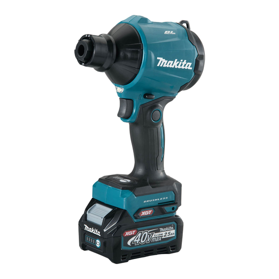
Cordless dust blower
Hide thumbs
Also See for AS001G:
- Instruction manual (161 pages) ,
- Instruction manual (25 pages) ,
- Instruction manual (124 pages)
Table of Contents
Advertisement
Quick Links
Advertisement
Table of Contents

Related Manuals for Makita AS001G


Summary of Contents for Makita AS001G
- Page 1 INSTRUCTION MANUAL Cordless Dust Blower AS001G Read before use.
-
Page 2: Specifications
SPECIFICATIONS Model: AS001G *2 *3 Air speed (average) 163 m/s *2 *3 Air speed (max.) 200 m/s *1 *2 Maximum air volume 1.1 m /min *1 *2 Maximum blowing force 4: Max 2.8 N (0.29 kgf) 3: High 2.3 N (0.23 kgf) 2: Medium 1.7 N (0.17 kgf) - Page 3 Applicable nozzles and attachments Nozzles and attachments Applications and purposes Diameters Nozzle 3 Blowing air into confined spaces, corners, and spaces by the walls to ø3.0 mm dust off. Nozzle 7 Dusting off filters. ø7.0 mm Nozzle 13 ø13 mm Using as blower Cleaning work surfaces and blowing dust in general. Anchor hole cleaning with optional long nozzles. Functioning as a joint between long nozzles and blower outlet of the tool.
- Page 4 Nozzles and attachments Applications and purposes Diameters Long nozzles set A set of nozzles suitable for blowing dust out of anchor holes and narrow ø8.0 mm spots. Nozzle lengths can be changed by attaching and detaching two nozzle heads. * Long nozzles can be installed using nozzle 13 as a joint. Air vent hose complete Deflating inflatable items with appropriate nozzles in operation.
-
Page 5: Safety Warnings
Symbols WARNING: Wear ear protection. WARNING: The noise emission during actual The followings show the symbols which may be used use of the power tool can differ from the declared for the equipment. Be sure that you understand their value(s) depending on the ways in which the tool is meaning before use. - Page 6 Work area safety Do not overreach. Keep proper footing and balance at all times. This enables better control Keep work area clean and well lit. Cluttered or of the power tool in unexpected situations. dark areas invite accidents. Dress properly. Do not wear loose clothing or Do not operate power tools in explosive atmo- jewellery.
- Page 7 • manufacturer or authorized service providers. blower outlet with dust or dirt when oper- Follow instruction for lubricating and chang- ating in dusty area. ing accessories. Do not use nozzles other than the nozzles • provided by Makita. 7 ENGLISH...
- Page 8 Use only standard accessories provided or vibration, immediately switch off the dust by Makita. The use of any other accessories blower to stop it. Remove the battery car- or attachments might present a risk of injury to tridge from the dust blower and inspect the persons.
- Page 9 Do not expose battery cartridge to water also void the Makita warranty for the Makita tool and or rain. charger. A battery short can cause a large current...
- Page 10 ASSEMBLY NOTE: While the polished surfaces of the nozzle end remain visible out of the lock sleeve, the nozzle is being inappropriately placed. Reassemble the nozzle in a correct position so the polished surfaces of the CAUTION: Always be sure that the tool is nozzle end become invisible under the lock sleeve.
- Page 11 Removing and installing dust cap Installing and removing long nozzles Turn the dust cap on the suction inlet at the rear of the housing counterclockwise to take the dust cap out Optional accessory of the housing. Two locking tabs on the dust cap can be A set of long nozzles help clean dust out of small holes disengaged by aligning them with the guide grooves on and narrow spots.
- Page 12 Place the long nozzle F over the front end of the Installing and removing deflating long nozzle R. Hand screw the long nozzle F until you nozzles and attachments find it roughly tightened, then re-tighten it further until it is secured with a click. Optional accessory NOTICE: Always be sure to install and uninstall deflating nozzles and attachments only while the air vent hose complete is disconnected from the tool.
- Page 13 Attach the end of the air vent hose complete to NOTE: While the polished surfaces of the nozzle end the suction inlet, aligning the two locking tabs on the remain visible out of the lock sleeve, the nozzle is air vent hose complete with the guide grooves on the being inappropriately placed.
-
Page 14: Functional Description
Replace an optional high performance filter on FUNCTIONAL the suction inlet, aligning the two locking tabs on the optional filter with the guide grooves on the housing. DESCRIPTION Then turn the optional filter clockwise to secure it in place. CAUTION: Always be sure that the tool is switched off and the battery cartridge is removed before adjusting or checking function on the tool. Installing or removing battery cartridge CAUTION:... -
Page 15: Overheat Protection
Fig.19 Let the tool and battery(ies) cool down. ► 1 . Indicator lamps 2. Check button If no improvement can be found by restoring protection system, then contact your local Makita Service Center. Indicator lamps Remaining Switch action capacity... - Page 16 Adjusting air volume NOTICE: Do not pull the switch trigger hard without releasing the trigger-lock button. This can cause switch breakage. Air volume can be changed in four modes, that is, 4 (Max), 3 (High), 2 (Medium) and 1 (Low), depending on Switch trigger the application and workload.
-
Page 17: Installing Hook
Use the hanging hole at the top rear of the housing to Lighting up the lamp hang the tool on a hook of racks and holders. CAUTION: Do not look in the light or see the source of light directly. To turn the lamp on, perform one of the following steps. -
Page 18: Operation
OPERATION CAUTION: Do not point the nozzle at anyone nearby during operation. NOTICE: Do not block suction inlet and/or blower outlet during operation. Blowing in general use Recommended nozzles Fig.29 — Nozzle 13 Clean your work surfaces and floors by blowing off dust, CAUTION: Keep the nozzle away a reasonable dirt, debris, scrap or waste in general. - Page 19 Inflate beach toys, pillows, and similar small plastic CAUTION: Use personal protective equip- inflatables with pinch valve nozzle. ment such as a dust mask and eye protection. Inflate garden pools, air mattresses, and similar large plastic inflatables with nozzle 13. NOTE: Point the nozzle at an angle according to the Insert the nozzle into an air inlet on an inflatable item outlines of the filter so the adhered dust can be easily and pull the switch trigger to start inflating. removed. Slowly release the switch trigger to reduce air volume as the inflatable item comes close to fully inflated.
- Page 20 CAUTION: Use personal protective equip- ment such as a dust mask and eye protection. Blowing in narrow spaces Optional accessory Recommended nozzles — Flexible nozzle 6 Blow dust out of any hard-to-reach spots. Highly effec- tive for engine cleaning, in-car dust removal, computer case dust blowing. Fig.35 Point the nozzle at an angle within touching distance, ► 1 .
-
Page 21: Maintenance
Insert the nozzle into the air valve or place the To maintain product SAFETY and RELIABILITY, attachment over the air valve on inflatable items, and repairs, any other maintenance or adjustment should pull the switch trigger to start deflating. be performed by Makita Authorized or Factory Service Centers, always using Makita replacement parts. Slowly release the switch trigger to reduce suction volume as an inflatable item comes close to fully deflated. NOTICE: Never use gasoline, benzine, thinner, alcohol or the like. - Page 22 Wipe and shake dust off circular sponge filter B by Removing and installing filter hand. Occasionally wash the filter in water, rinse and dry thoroughly in the shade before use. CAUTION: After cleaning filter, be sure to reassemble it in the correct position. Clean the filter at regular intervals since using a clogged filter may result in poor suction performance. Turn the dust cap on the suction inlet at the rear of the housing counterclockwise to take the dust cap out of the housing.
-
Page 23: Troubleshooting
► 1 . Dust cap 2. Locking tabs 3. Suction inlet 4. Guide grooves TROUBLESHOOTING Before asking for repairs, conduct your own inspection first. If you find a problem that is not explained in the man- ual, do not attempt to dismantle the machine. Instead, ask Makita Authorized Service Centers, always using Makita replacement parts for repairs. State of abnormality Probable cause (malfunction) Remedy Motor does not run. -
Page 24: Optional Accessories
OPTIONAL ACCESSORIES CAUTION: These accessories or attachments are recommended for use with your Makita prod- uct specified in this manual. The use of any other accessories or attachments might present a risk of injury to persons. Only use accessory or attachment for its stated purpose. If you need any assistance for more details regarding these accessories, ask your local Makita Service Center.
Need help?
Do you have a question about the AS001G and is the answer not in the manual?
Questions and answers