COBHAM EXPLORER 540 Installation Manual
Hide thumbs
Also See for EXPLORER 540:
- User & integrator's manual (172 pages) ,
- User manual (134 pages) ,
- Setup manual (5 pages)
Advertisement
Quick Links
EXPLORER 540
Installation guide
What's in the box?
The following items are included in the
delivery:
• EXPLORER 540 terminal
• Pole mount kit
• 2 standard cable glands
• 2 C1D2 approved cable glands
• 1 Blanking plug
• Torx bit Size TX10 (tamper resi-
stant, 1/4" Hex drive) for mounting/
unmounting the cover for the
interface enclosure
• Installation guide (this guide)
EXPLORER 540 User and integrator's manual (part no. 98-148232) as well as other language
versions of this installation guide are available for download at the Cobham SYNC Partner
Portal. Go to www.cobham.com/satcom and select Cobham SYNC Partner Portal > Downloads.
Step 2: Connect cables
To maintain the Ingress Protection rating of the EXPLORER 540 and to avoid cables acciden-
tally being disconnected, all cable connections are made inside the interface enclosure at the
back of the EXPLORER 540.
Tools:
• Use the provided Torx bit to open the interface enclosure at the back of the terminal
• Use a flat blade screw driver (max. 2 mm/ 0.08" wide) to press down the spring-loaded
terminals
• Use a flat blade screw driver (max. 3.5 mm/ 0.14" wide) to unscrew and fasten the screw
terminals
X2: Ethernet,
RJ-45
X1: Ethernet,
Spring-loaded
terminals
X7: Chassis GND,
Screw terminal
1. Lead the cable(s) through the cable gland(s) and gasket(s) (suitable for cable diameter
5-10 mm/ 0.2"-0.4"). For C1D2 installations, use the supplied C1D2 approved cable glands.
Make sure the cable glands fit tightly.
2. Connect the cables according to your
configuration. See the reverse of this
guide for pinout, specifications and
example configuration drawing.
The RJ-45 connector of the LAN cable
can pass through the standard cable
gland. (see picture)
3. If you are not using PoE to power
the EXPLORER 540, connect a power
cable between the DC input terminals
and a current-limited power supply
or an external battery as described
below.
4. When all cables are connected, mount the cover for the interface enclosure and tighten
the screws with the included Torx bit.
Important! If you only need to install one cable, mount the provided blanking plug in the
unused hole to maintain the Ingress Protection (IP grade) of the terminal.
To connect to the DC input:
1. Lead the cable through the cable gasket
at the DC input.
2. If the DC cable is shielded, insert the end
of the shield into the screw terminal
marked 3-GND and tighten the screw to
torque 0.5 N m/ 4.5 lbf in.
3. Insert the negative wire into the termi-
nal marked 2-DCIN - in the DC terminal
block and tighten the screw to torque
0.5 N m /4.5 lbf in.
4. Insert the positive wire into the terminal
marked 1-DCIN + in the DC terminal
block and tighten the screw to torque
0.5 N m/ 4.5 lbf in.
5. Tighten the cable gland.
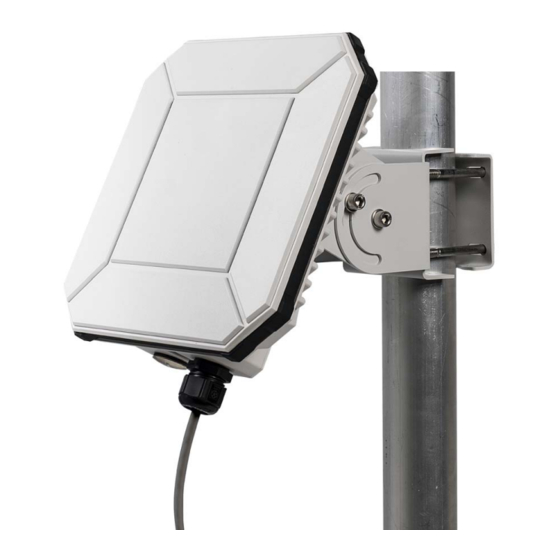
EXPLORER 540 terminal
with pole mount kit
X6: USB Micro B
(in the side wall -
not visible here)
X4: DC input,
Screw terminals
X5: I/O,
Spring-loaded
terminals
Caution!
Do not connect the
positive or negative
wire to 3-GND!
Step 1: Insert SIM card
You need a BGAN SIM card for either BGAN M2M or BGAN class 2 services. To insert the SIM
card, do as follows:
NOTE: Make sure the EXPLORER 540 is not
powered when you insert or remove the SIM
card!
1. Open the cover for the interface enclosure
at the back of the
EXPLORER 540. Use the included Torx bit
to unscrew the screws.
2. Locate the SIM holder in the middle of the
compartment.
3. Slide the lock to release the SIM holder.
4. Lift the end of the SIM holder and insert
the SIM card as shown.
5. Lower the SIM card holder with the SIM
card inserted and lock it.
6. When all cables are connected, put the
cover back on and tighten the screws.
NOTE: Make sure the PIN for the SIM card is
either disabled or set up for automatic valida-
tion. For details, see the EXPLORER 540 User
and integrator's manual.
Step 3: Install the EXPLORER 540
A pole mount kit is included in the package. To mount the EXPLORER 540 on a pole, do as
follows:
1. Attach the base of the pole mount
bracket to the EXPLORER 540 using the
included Hex L key on the 4 screws. Cau-
tion! Max. length of the screws is 9 mm/
0.35"! Longer screws can damage the
EXPLORER 540.
2. Unscrew two of the long screws from the
pole mount kit to leave one side open for
the pole.
3. Place the pole mount kit with the
EXPLORER 540 around the pole as shown.
4. Remount the two remaining long screws.
Do not tighten the screws completely until
you have pointed the antenna.
5. Power up the system.
Observe the LED between the cable glands
(see LED description on the back).
• LED flashing rapidly green: Starting up
• LED flashing yellow: Pointing
• LED steady yellow: Warning!
See Verifying and troubleshooting
the installation on the back.
6. When LED flashes yellow: Turn and tilt the
EXPLORER 540 and use the pointing sound
to obtain the highest possible signal
strength (continuous sound = best signal).
7. When you have the highest possible
signal strength, tighten all the screws on
the pole mount kit to keep the EXPLORER
540 in the pointed positionThe EXPLORER
540 will automatically exit the pointing
process once it has detected a stable
BGAN signal.
8. When the pointing process has ended, the
LED changes as follows:
• LED flashing green:
Verifying network connection
• LED steady green and then off:
Ready - installation process has ended
successfully. The LED is disabled (off)
after a few minutes.
Note: If the LED is steady yellow, it means the
installation failed and there is a warning.
If you can connect a computer locally to the EXPLORER 540, you can use the web interface to
follow the progress on screen, see any warnings, and restart the installation if necessary. See
Verifying and troubleshooting the installation on the back.
Note: The installation will fail if the SIM card requires a user defined APN value and you have
not yet entered this in the EXPLORER 540. Specify the APN value and restart the installation.
For details, see the EXPLORER 540 User and integrator's manual.
If the equipment is used in a manner not specified by the manufacturer, the protection
provided by the equipment may be impaired.
Cleaning: Clean the exterior of the EXPLORER 540 with a damp cloth.
Disclaimer: Any responsibility or liability for loss or damage in connection with the use of this product and the accompanying documentation is disclaimed by
Thrane & Thrane A/S. The information in this manual is provided for information purposes only, is subject to change without notice and may contain errors or
inaccuracies. The manuals are periodically revised and updated. Anyone relying on this information should acquire the most current version e.g. from cobham.
com/satcom or from the distributor. Thrane & Thrane A/S is not responsible for the content or accuracy of any translations or reproductions, in whole or in
part, of this manual from any other source. Thrane & Thrane A/S trading as Cobham SATCOM.
Copyright © 2019 Thrane & Thrane A/S. All rights reserved.
Manufacturer address: Thrane & Thrane A/S, Lundtoftegaardsvej 93 D, DK-2800, Kgs. Lyngby, Denmark
Pole size
1" to 1.5"
(33.7 to 48.3 mm)
LED =
LED =
Advertisement

Related Manuals for COBHAM EXPLORER 540


Summary of Contents for COBHAM EXPLORER 540
- Page 1 5. Tighten the cable gland. inaccuracies. The manuals are periodically revised and updated. Anyone relying on this information should acquire the most current version e.g. from cobham. com/satcom or from the distributor. Thrane & Thrane A/S is not responsible for the content or accuracy of any translations or reproductions, in whole or in part, of this manual from any other source.
- Page 2 Configurable in web interface: 1. Connect your computer to the LAN interface of EXPLORER 540. Request wake up or Power save on/off and 2. Open your browser on the con- Active high or low nected computer.
Need help?
Do you have a question about the EXPLORER 540 and is the answer not in the manual?
Questions and answers