Table of Contents
Advertisement
Quick Links
Advertisement
Table of Contents

Subscribe to Our Youtube Channel
Related Manuals for Xylem SI Analytics ViscoClock plus


Summary of Contents for Xylem SI Analytics ViscoClock plus
- Page 1 OPERATING MANUAL ViscoClock plus VISCOSITY MEASURING DEVICE...
- Page 2 Gebrauchsanleitung ....................Seite 3 ... 32 Wichtige Hinweise: Die Gebrauchsanleitung ist Bestandteil des Gerätes. Vor der ersten Inbetriebnahme bitte sorgfältig lesen, beachten und anschließend aufbewahren. Aus Sicherheitsgründen darf das Gerät ausschließlich für die beschriebenen Zwecke eingesetzt werden. Bitte beachten Sie auch die Gebrauchsanleitungen für eventuell anzuschließende Geräte.
-
Page 3: Table Of Contents
TABLE OF CONTENT Technical Specifications of the ViscoClock plus..........35 Intended Use ........................... 35 Specifications of the ViscoClock plus ..................36 Description of the device ......................37 Warnings and safety information ..................... 38 Mode of operation ........................39 Unpacking and Setup .................... 39 Commissioning ...................... - Page 4 A potentially more recent version of this manual is available on our internet website at www.si-analytics.com. The German version is the original version and binding in all specifications. Copyright © 2016, Xylem Analytics Germany GmbH Reprinting - even as excerpts - is only allowed with the explicit written authorization. Printed in Germany.
-
Page 5: Technical Specifications Of The Viscoclock Plus
Technical Specifications of the ViscoClock plus 1.1 Intended Use The ViscoClock plus is an electronic viscosity measuring device. ® Use only viscometers of the brand SI Analytics (Ubbelohde, Micro Ubbelohde or Micro Ostwald)! The ViscoClock plus automatically measures the time which a liquid requires to flow from the upper to the lower timing mark of the measurement bulb through the capillaries of the viscometer. -
Page 6: Specifications Of The Viscoclock Plus
1.2 Specifications of the ViscoClock plus (Release: 19. December 2016) CE sign: As per the low voltage directive 2014/35/EU; test basis EN 61 010-1: 2011-07 for laboratory devices As per the EMC directive 2014/30/EU; test basis EN 61 326 Part 1: 2012 As per the EMC directive 2011/65/EU;... -
Page 7: Description Of The Device
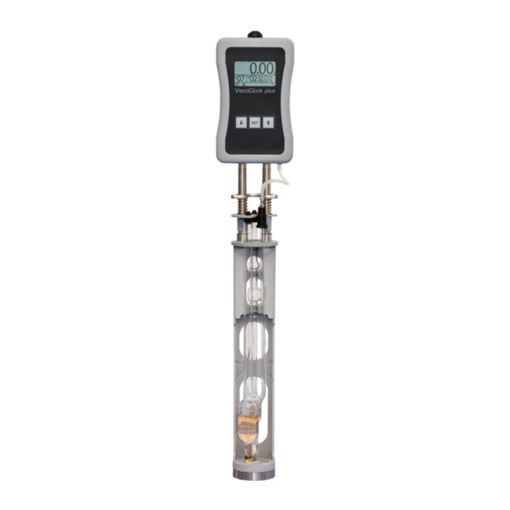
1.3 Description of the device Leg made from stainless steel to weigh down the unit Centering prism for positioning and holding the viscometer Stand Lower measurement level Upper measurement level Guide plate for viscometer centering Fixation plate for positioning and holding the viscometer 8D Silicone plug for fill tube for pushing operation 8S Silicone plug for capillary tube for suction operation Handle plate... -
Page 8: Warnings And Safety Information
1.4 Warnings and safety information The ViscoClock plus unit is protected as per protection class III. It was manufactured and tested according to DIN EN 61 010 - 1, Part 1, "Protective Measures for electronic measurement devices and control devices" and has left the factory in an impeccable condition as concerns safety technology. -
Page 9: Mode Of Operation
1.5 Mode of operation ® The ViscoClock plus automatically measures the flow time of a liquid in an SI Analytics viscometer to determine the relative and kinematic (absolute) viscosity. The time measured is the time which a liquid requires to flow from the upper to the lower measurement mark of the measurement bulb through the capillaries of the viscometer. -
Page 10: Commissioning
3 Commissioning 3.1 Viscometer models to be used The following viscometer models can be used in the ViscoClock plus: 21 Filling tube 22 Capillary tube 23 Venting tube 24 Measuring bulb 25 Feeder bulb 26 Level vessel 27 Reservoir vessel Ubbelohde Micro Ubbelohde Micro Ostwald... -
Page 11: Selection Of The Viscometer
3.2 Selection of the viscometer The flow time of the liquid to be measured depends on the size of the capillaries. The capillary size of the viscometer should be selected in such a manner that flow times greater than 100 s result ®... -
Page 12: Preparation Of The Sample
3.3 Preparation of the sample If the samples to be measured (measuring liquids) may contain particles, they must be filtered prior to being introduced into the viscometer. For low viscosity liquids, the following filters are recommended a) Low-viscosity liquids: • ®... -
Page 13: Place The Viscometer Into The Viscoclock Plus
3.4 Place the viscometer into the ViscoClock plus Press the guidance plate (7) up against the handle plate (9) (see Fig. 3). - The following applies to the use of Ubbelohde and Micro Ubbelohde viscometers: • Insert the viscometer sloped through the guidance plate (6), and then insert it vertically into the centering (2) prism. -
Page 14: Place The Viscoclock Plus Into The Thermostat Bath
3.5 Place the ViscoClock plus into the thermostat bath The transparent thermostat has to be equipped with a VZ 5402 manual measuring insert in order to accommodate the ViscoClock plus. Insert the ViscoClock plus, including the viscometer filled with measuring liquid, into the manual measuring insert of the thermostat bath (see ... -
Page 15: Connection Of A Usb Drive
3.7.1 Connection of a USB drive To transfer the measured data to a USB drive, this can simply be connected to the USB-A connector (18). As an alternative, the connection can also be made via the USB Mini-B socket (17) via an optional USB OTG adapter cable VZ6570. -
Page 16: Simultaneous Connection Of A Usb Drive And The Printer Tz 3863
3.7.3 Simultaneous connection of a USB drive and the printer TZ 3863 For the simultaneous connection of both USB drives and the printer, one device is connected to the USB- A connector (18) and the other device is connected to the USB Mini-B connector (17) via the OTG adapter cable VZ6570 (optional accessory). -
Page 17: Prepare For Measurement
3.8 Prepare for measurement • Wait for the tempering time of the sample in the thermostat bath, depending on the application type, 5…15 minutes • Pumping the sample into the measuring sphere of the viscometer: The liquid should be pumped to approx. 1 - 2 cm above the top measuring level. For Ubbelohde viscometers, the feeder bulb (24) is located above the measuring bulb (25) (see ... -
Page 18: Start Measurement
(b) on silicone plug (8S) above the capillary tube (22) for suction operation (see Fig. 9) Fig. 9 Suction mode liquid handling with manual pump VZ 6554 The suction operation with manual pump VZ 6554 (optional accessory, not included in the scope of delivery), is recommended especially for aggressive liquids which must never enter the thermostat bath inadvertently. -
Page 19: Reading The Flow Time
Fig. 10 Start measurement This will: • set the display to zero • release the venting tube (1) (only applies to Ubbelohde viscometers) • trigger the measurement Once the meniscus of the measuring liquid runs through the upper measurement level (5), the time measurement begins and when it passed the lower measuring level (4), time measurement ends. -
Page 20: Evaluation Example
For absolute measurements of viscosity, the corrected flow time multiplied by the constants indicated in the viscometer certificate K results immediately in the kinematic viscosity in the unit mm ν = K (t-∆t Relative viscosity is the quotient of the viscosities of a solution and the pure solvent. This has a high significance in the evaluation of plastics. -
Page 21: Description And Use Of Software
4 Description and use of software 4.1 Display The main screen ( Fig. 11) of the ViscoClock plus displays all relevant information clearly on a graphics display. A: Measuring time (flow time) B: Sample number (S=Sample) C: Viscometer number (V=Viscometer) D: Time/date E: Number of measurements (internal memory) F: Beeper on/off... -
Page 22: Set Up Sample Or Viscosity Numbers
4.4 Set up sample or viscosity numbers To set up the sample number, press the <↓> key. The sample number (B) will blink and then you can use the <↑> and <↓> keys to set up numbers between 0 and 99. To set up the viscosity number, press the <↑>... -
Page 23: Save Or Print Measurements
4.7 Save or print measurements 4.7.1 Internal memory The ViscoClock plus has an internal memory (clipboard) for up to 99 measuring results. Every carry out measurement is saved in this memory and remains intact even after the supply voltage is disconnected. -
Page 24: Printing Measuring Results
4.7.3 Printing measuring results The measuring results saved in the internal memory can be printed by means of a printer connected via the USB interface (TZ 3863 or other printer compatible with the ViscoClock plus). A recognized printer is displayed via a respective symbol (H) in the lower status bar. In order to print, press the <SET>... -
Page 25: Tips For Using The Usb Interface
4.7.6 Tips for using the USB interface The USB drive must be formatted in the FAT16 or FAT32 file system. We recommend using a USB drive. External hard drives without power supplies cannot be used. During a measurement run, you should not connect or disconnect any USB drives, as the measurement will be terminated in case of an error. -
Page 26: Master Reset
The following image shows a cutout of a personalized result printout: Fig. 12 PDF result printout with personalized header 4.10 Master Reset Use the Master Reset function, all settings and memory slots can be set back to factory values. For this, press and hold the <↑> and <↓> keys for at least 3 seconds. A message will be displayed prompting you to perform a restart. -
Page 27: Maintenance
5 Maintenance 5.1 General notes Using alkaline laboratory cleaners poses a health hazard (chemical burns, injuries to skin and eyes)! • Use personal protective equipment during the cleaning process, such as: Eye protection, protective gloves, laboratory coat, respiratory protection. • Please observe the memorandums of the employer's liability insurance associations and the safety data sheets of the manufacturers. -
Page 28: Faults And Error Messages
6 Faults and error messages 6.1 Faults • The display is dark. Cause Remedy Power supply has been disrupted. Check connection/function of plug. • The sample cannot be pushed or suctioned up. Cause Remedy The silicone plug (8) is not properly seated Check the silicon stopper for tight seating. - Page 29 • Liquid dripping from ViscoClock plus. Cause Remedy The <START> key (16) was pressed prior to Contact the Service Center (see backside of this manual) pumping up so that the ventilation valve is or the dealer. open. Sample was pumped into the measuring device ViscoClock plus with the manual pump.
-
Page 30: Error Messages
6.2 Error messages • Error while measuring Display Error code Errors Description Remedy message 0x02000201 Timeout at Timeout at upper 1. Viscometer is not 1. Check the position of upper LB light barrier positioned properly. the viscometer. (A measurement was started;... - Page 31 • Error during setting up of USB drives Error code Display message Errors Description Remedy 0x02000E01 Two USB keys A max. of 1 A second USB drive was Use only one USB not supported USB drive connected, but only one medium supported is supported...
- Page 32 7 Guarantee We provide guarantee for the device described for two years from the date of purchase. This guarantee covers manufacturing faults being discovered within the mentioned period of two years. Claim under guarantee covers only the restoration of functionality, not any further claim for damages or financial loss. Improper handling/use or illegitimate opening of the device results in loss of the guarantee rights.
- Page 36 Xylem Analytics Germany Sales GmbH & Co.KG SI Analytics Gebäude G12, Tor Rheinallee 145 55122 Mainz Germany Tel. +49(0)6131.66.5042 Fax. +49(0)6131.66.5105 E-Mail: Service-Instruments.si-analytics@xyleminc.com SI Analytics is a trademark of Xylem Inc. or one of its subsidiaries. © 2016 Xylem, Inc. Version 161219 US 825 295 3...
Need help?
Do you have a question about the SI Analytics ViscoClock plus and is the answer not in the manual?
Questions and answers