Table of Contents
Advertisement
Quick Links
Advertisement
Table of Contents

Related Manuals for Xylem FLYGT Start 151


Summary of Contents for Xylem FLYGT Start 151
- Page 1 Installation and Operation Manual Start 151/161/156...
-
Page 3: Table Of Contents
Table of Contents Table of Contents 1 Introduction and Safety.................... 2 1.1 Introduction......................2 1.2 Safety terminology and symbols..............2 1.3 User safety......................3 1.4 End of life product disposal................4 1.5 Spare parts......................5 1.6 Warranty......................5 1.7 Support....................... 5 2 Product Description.................... -
Page 4: Introduction And Safety
This includes any modification to the equipment or use of parts not provided by Xylem. If there is a question regarding the intended use of the equipment, please contact a Xylem representative before proceeding. -
Page 5: User Safety
1 Introduction and Safety Hazard levels Hazard level Indication A hazardous situation which, if not avoided, will DANGER: result in death or serious injury A hazardous situation which, if not avoided, could WARNING: result in death or serious injury A hazardous situation which, if not avoided, could CAUTION: result in minor or moderate injury Notices are used when there is a risk of equipment... -
Page 6: End Of Life Product Disposal
Risk of electrical shock or burn. A certified electrician must supervise all electrical work. Comply with all local codes and regulations. All work on the product must be carried out by certified electricians or Xylem authorized mechanics. Xylem disclaims all responsibility for work done by untrained, unauthorized personnel. -
Page 7: Spare Parts
1.6 Warranty For information about warranty, see the sales contract. 1.7 Support Xylem only supports products that have been tested and approved. Xylem does not support unapproved equipment. Start 151/161/156 Installation and Operation Manual... -
Page 8: Product Description
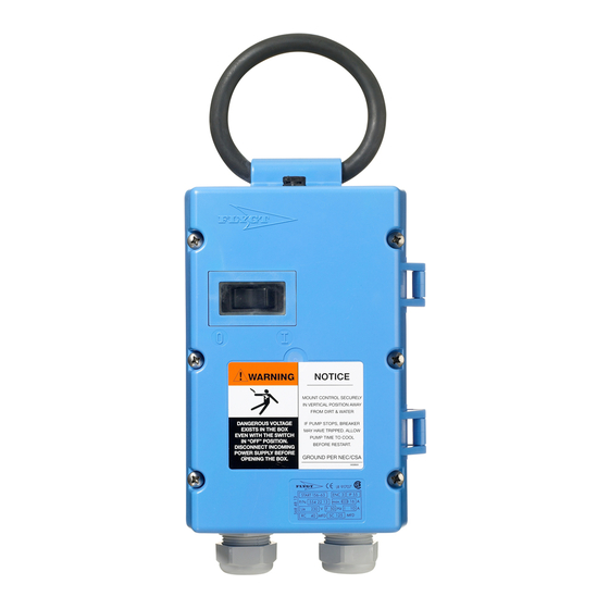
2 Product Description 2 Product Description 2.1 Product design This unit is a manual starter that is well suited for rugged applications such as building sites. Design features include a robust plastic casing and ON and OFF buttons inset into the front, for manually starting and stopping the pump. Automatic operation of the pump, for example with level control equipment, is not possible. -
Page 9: The Data Plate
2 Product Description 2.2 The data plate 1. Degree of protection 2. Part number 3. Type designation 4. Maximum fuse rating 5. Voltage 6. Frequency 7. Current range 8. Run capacitor 9. Start capacitor 2.3 Technical data Table 1: Electrical characteristics Parameter Value Supply voltage/frequency *... - Page 10 2 Product Description Feature Value Ambient temperature –25° to +40°C (–13°F to +104°F) Table 4: Maximum connection area Conductor Maximum Solid conductor 1 x 1..10.0 mm 2 x 1..4.0 mm Multiple-strand conductor 1 x 1..6.0 mm 2 x 1..2.5 mm Start 151/161/156 Installation and Operation Manual...
-
Page 11: Installation
3 Installation 3 Installation 3.1 Facility requirements Exposure to water or physical damage The starter has a high degree of protection against moisture and dirt, but it should always be installed so that it will not be unnecessarily exposed to water or the risk of external physical damage. -
Page 12: Wiring Diagram
3 Installation DANGER: Electrical Hazard All electrical equipment must be grounded (earthed). Test the ground (earth) lead to verify that it is connected correctly and that the path to ground is continuous. The current for the motor protection switch is preset, and has been matched at the factory to the rated current of the motor. -
Page 13: External Connections
3 Installation European Version North American Version Terminal Cable Color Terminal Cable Color Brown Black Black Grey White Green/yellow Green/yellow T1/white * Orange * T2/white * Blue * * Only for starter type B 3.4 External connections 3.5 Commissioning WARNING: Explosion/Fire Hazard The start capacitor is not designed for many repeated start cycles in a short time. - Page 14 3 Installation Figure 1: Start reaction Start 151/161/156 Installation and Operation Manual...
-
Page 15: Troubleshooting
The motor protection breaker Let the motor cool down, and trips. then restart the pump. The pump rotates in the wrong The internal connections of the Contact a Xylem service direction motor are wrong. representative. The pump starts but runs Low voltage... -
Page 16: Spare Parts
4 Troubleshooting Fault Reason Action The motor protection breaker Incorrect setting range Check on the rating plates that trips. the rated current ranges of the pump and starter agree. Low voltage Cables are too long or under- dimensioned. Overloaded motor The impeller is binding due to clogging. - Page 20 For more information on how Xylem can help you, go to xyleminc.com Xylem Water Solutions Global Visit our Web site for the latest...
Need help?
Do you have a question about the FLYGT Start 151 and is the answer not in the manual?
Questions and answers