Table of Contents
Advertisement
Quick Links
SSM2529 REV 1 EVALUATION BOARD OPERATION (PRELIMINARY!)
Description of Setup:
The SSM2529 evaluation setup consists of the following:
1) A fully integrated SSM2529 evaluation board, EVAL-SSM2529
2) Analog Devices USB-to-I2C adapter dongle, EVAL-ADUSB2Z.
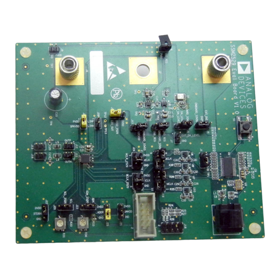
The SSM2529 can operate in stand-alone mode without the need for I2C control, as shown in Figure 1. In order to
evaluate full functionality of the SSM2529, the user must use I2C. A GUI has been developed using the SigmaStudio
development platform. The ADUSB2Z dongle is able to interface between the GUI and the evaluation board, as
shown in Figure 2.
Figure 1: Picture of SSM2529 Evaluation Board (operating in stand-alone mode, without I2C)
Digital Audio Group, Analog Devices, Inc.
August 4, 2010
Advertisement
Table of Contents

Subscribe to Our Youtube Channel
Related Manuals for Analog Devices SSM2529


Summary of Contents for Analog Devices SSM2529
- Page 1 2) Analog Devices USB-to-I2C adapter dongle, EVAL-ADUSB2Z. The SSM2529 can operate in stand-alone mode without the need for I2C control, as shown in Figure 1. In order to evaluate full functionality of the SSM2529, the user must use I2C. A GUI has been developed using the SigmaStudio development platform.
-
Page 2: Section 1 - Power Supply
U7 – U10. I2CVDD: This is the pull-up voltage for the I2C pins of SSM2529. This voltage can be set to either ONBOARD_IOVDD or and external I2C pull-up by inserting a jumper across the designated pins of J17. -
Page 3: Section 2 - Digital Audio Source
Section 2 – Digital Audio Source: The SSM2529 evaluation board has two options for digital audio signals: 1) Use an external digital audio source, such as Audio Precision PSIA 2722 (source on J18), or 2) Use the onboard digital audio receiver and source digital audio using the TORX connection. -
Page 4: Section 3 - I2C Section
Section 3 – I2C Section: The SSM2529 can operate with or without I2C control. If it is desired to evaluate the part in Stand Alone mode, simply insert a jumper across the SAMOD and DVDD terminals of J21. To put the part into I2C mode, insert a jumper across the SAMOD and GND terminals of J21. -
Page 5: Section 4 - Gui / Adusb2 Installation
Figure 7: SSM2529 I2C Mode Configuration using ADUSB2 Dongle Section 4 – GUI / ADUSB2 Installation: A graphical user interface for the SSM2529 has been created in the Analog Devices, Inc. SigmaStudio environment. SigmaStudio must first be downloaded and installed on the user’s PC from the following link: http://www.analog.com/en/audiovideo-products/audio-signal-... -
Page 6: Section 4 - Gui Operation
4) Click the “Link Compile Connect” icon on the SigmaStudio toolbar to initialize communication from the PC to the ADUSB2 dongle and SSM2529 evaluation board. 5) The various user interface options are available by selection via a right mouse click on the main SSM2529 icon in the Hardware Configuration window. - Page 7 Figure 8: SSM2529 GUI – Initial Project Setup in SigmaStudio (*note, Link-Compile-Connect button is highlighted) Figure 9: SSM2529 GUI – Main Functionality Window...
- Page 8 Figure 10: SSM2529 GUI – EQ Functionality Window Figure 11: SSM2529 GUI – DRC Functionality Window...
- Page 9 Figure 12: SSM2529 GUI – I2C Register Direct Read/Write Window...
Need help?
Do you have a question about the SSM2529 and is the answer not in the manual?
Questions and answers