Table of Contents
Advertisement
Quick Links
One Technology Way • P.O. Box 9106 • Norwood, MA 02062-9106, U.S.A. • Tel: 781.329.4700 • Fax: 781.461.3113 • www.analog.com
Evaluation Board for SSM2317 Filterless Class-D Audio Amplifier
PACKAGE CONTENTS
SSM2317-EVALZ
OTHER SUPPORTING DOCUMENTATION
SSM2317 data sheet
GENERAL DESCRIPTION
The
SSM2317
is a fully integrated, single-chip, mono Class-D audio
amplifier that is designed to maximize performance for mobile phone
applications. The application circuit requires a minimum of exter-
nal components and operates from a single 2.5 V to 5.5 V supply. It
is capable of delivering 3 W of continuous output power with less
than 1% THD + N driving a 3 Ω load from a single 5.0 V supply.
The SSM2317 is equipped with a differential mode input port and a
high efficiency, full H-bridge at the output that enables direct coupling
of the audio power signal to the loudspeaker. The differential mode
input stage allows for cancelling of common-mode noise.
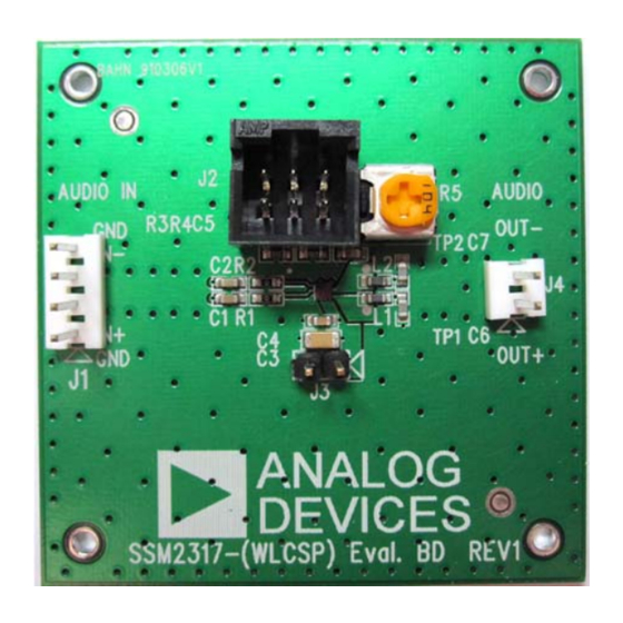
Figure 1. SSM2317 Evaluation Board Top View
PLEASE SEE THE LAST PAGE FOR AN IMPORTANT
WARNING AND LEGAL TERMS AND CONDITIONS.
Arrow.com.
Downloaded from
Evaluation Board User Guide
Automatic level control (ALC) can be activated to suppress
clipping and improve dynamic range. This feature only requires
one external resistor tied to GND via the VTH pin and an
activation voltage on the ALC_EN pin. For setup configuration
and sync operation, see the SSM2317 data sheet.
The part also features a high efficiency, low noise output modulation
scheme that does not require external LC output filters when
attached to an inductive load. The modulation provides high
efficiency even at low output power. Filterless operation also helps
to decrease distortion due to the nonlinearities of output LC filters.
This user guide describes how to configure and use the SSM2317
evaluation board to evaluate the SSM2317. It is recommended
that this data sheet be read in conjunction with the SSM2317
data sheet, which provides more detailed information about the
specifications, internal block diagrams, and application guidance
for the amplifier IC.
EVALUATION BOARD OVERVIEW
The SSM2317 evaluation board carries a complete application
circuit for driving a loudspeaker. Figure 1 shows the top view of
the evaluation board, and Figure 2 shows the bottom view.
Figure 2. SSM2317 Evaluation Board Bottom View
Rev. 0 | Page 1 of 8
UG-192
Advertisement
Table of Contents

Related Manuals for Analog Devices SSM2317-EVALZ


Summary of Contents for Analog Devices SSM2317-EVALZ
-
Page 1: Package Contents
PACKAGE CONTENTS Automatic level control (ALC) can be activated to suppress clipping and improve dynamic range. This feature only requires SSM2317-EVALZ one external resistor tied to GND via the VTH pin and an OTHER SUPPORTING DOCUMENTATION activation voltage on the ALC_EN pin. For setup configuration and sync operation, see the SSM2317 data sheet. -
Page 2: Table Of Contents
UG-192 Evaluation Board User Guide TABLE OF CONTENTS Package Contents................1 Output Configuration..............3 Other Supporting Documentation..........1 Power Supply Configuration ............3 General Description ................. 1 Component Selection ..............3 Evaluation Board Overview ............1 Getting Started................4 Revision History ................2 What to Test ...................4 Setting Up the Evaluation Board ............ -
Page 3: Setting Up The Evaluation Board
Evaluation Board User Guide UG-192 SETTING UP THE EVALUATION BOARD Polarity and Voltage INPUT CONFIGURATION The wrong power supply polarity or an overvoltage may damage A 4-pin header (J1) on the middle left side of the board feeds the the board permanently. The maximum peak current is approxi- audio signal into the board (see Figure 1). -
Page 4: Getting Started
UG-192 Evaluation Board User Guide Input Coupling Capacitor Selection—C1 and C2 Output Inductors The input coupling capacitors, C1 and C2, should be large enough If using inductors for the purpose of EMI filtering at the output to couple the low frequency signal components in the incoming nodes, choose inductance that is <2.2 μH for these inductors. -
Page 5: Evaluation Board Schematic And Artwork
Evaluation Board User Guide UG-192 EVALUATION BOARD SCHEMATIC AND ARTWORK HDR1X2 10µF 0.1µF B0603 OUT+ 0.1µF SSM2317/BGA 0Ω OUT+ HDR1X2 IN– OUT– 0Ω 0.1µF B0603 CON4 OUT– 100kΩ 100kΩ 0.1µF 100kΩ CON6A Figure 3. Schematic of the SSM2317 Evaluation Board Rev. - Page 6 UG-192 Evaluation Board User Guide Figure 4. Top Layer with Top Silkscreen Figure 6. Top Layer Figure 5. Top Silkscreen Figure 7. Layer 2 (Ground Plane) Rev. 0 | Page 6 of 8 Arrow.com. Arrow.com. Arrow.com. Arrow.com. Arrow.com. Arrow.com. Downloaded from Downloaded from Downloaded from Downloaded from...
- Page 7 Evaluation Board User Guide UG-192 Figure 8. Layer 3 (Power Plane) Figure 9. Bottom Layer Rev. 0 | Page 7 of 8 Arrow.com. Arrow.com. Arrow.com. Arrow.com. Arrow.com. Arrow.com. Arrow.com. Downloaded from Downloaded from Downloaded from Downloaded from Downloaded from Downloaded from Downloaded from...
-
Page 8: Ordering Information
By using the evaluation board discussed herein (together with any tools, components documentation or support materials, the “Evaluation Board”), you are agreeing to be bound by the terms and conditions set forth below (“Agreement”) unless you have purchased the Evaluation Board, in which case the Analog Devices Standard Terms and Conditions of Sale shall govern. Do not use the Evaluation Board until you have read and agreed to the Agreement.
Need help?
Do you have a question about the SSM2317-EVALZ and is the answer not in the manual?
Questions and answers