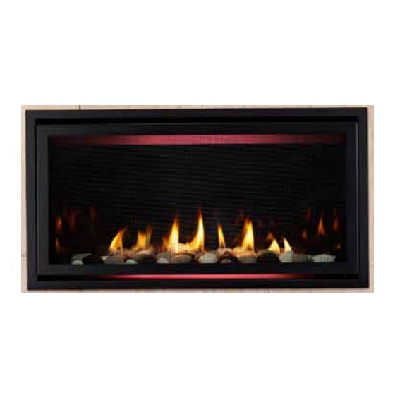
Advertisement
Models: RAVE3012I, SLR32, RAVE4013I-C, SLR-C, SLR-D,
Leave this manual with party responsible for use
and operation.
CAUTION! Risk of Cuts or Abrasions. Wear protective
gloves and safety glasses during installation. Sheet metal
edges are sharp.
DANGER
DO NOT TOUCH GLASS
NEVER ALLOW CHILDREN
A barrier designed to reduce the risk of
burns from the hot viewing glass is provided
with this appliance and shall be installed for
the protection of children and other at-risk
individuals.
This appliance has been supplied with an integral barrier
to prevent direct contact with the fi xed glass panel. DO
NOT operate the appliance with the barrier removed.
Contact your dealer or Hearth & Home Technologies if the
barrier is not present or help is needed to properly install one.
NOTICE: Handle refractory panels with care. Refractory
may chip or crack if dropped or impacted.
TOOLS
Screw gun equipped with 1/4 in. socket or
1/4 IN. wrench or socket
KIT COMPONENTS
(1) Left Refractory Panel
(1) Right Refractory Panel
(1) Back Refractory Panel
(4) Glass Retaining Brackets
Screws
Hearth & Home Technologies • Glass Panel Installation Instructions • 2264-940 Rev. i • 1/17
Glass Panel Installation Instructions
XLR-PLUS-AU, RAVE4013I-D, XLR-PLUS-AUB
HOT GLASS WILL
CAUSE BURNS.
UNTIL COOLED.
TO TOUCH GLASS.
Glass Panel Instructions
Note: If the lower panel is fi nished, the glass baffl e
will need to be removed on SLR-C, RAVE4013I-C,
SLR-D and RAVE4013I-D models before installing
panels. Replace baffl e after the glass panels have
been installed. The side media tray edges may also
need to be bent inward.
CAUTION! Risk of Injury! Glass baffl e MUST be re-
installed ,if removed. Appliance could overheat causing
glass to break.
1. Install back glass panel labeled A as shown in Figure
1. Back panel will be held in place by the side panels.
Hold back panel in place while installing the left / right
panels per steps 2 and 3.
Note: Install left and right glass panels with the
longer side to the front of the appliance as noted in
Figure 1.
2. Install left glass panel labeled B as shown in Figure 1.
Install retaining bracket with the screw provided. See
Figure 2.
SLR-C/SLR-D/RAVE4013I-C/RAVE4013I-D:
additional bracket to base pan with screw provided.
3. Install right glass panel labeled C as shown in Figure
1. Install retaining bracket with the screw provided.
See Figure 2.
SLR-C/SLR-D/RAVE4013I-C/RAVE4013I-D:
additional bracket to base pan with screw provided.
LONG SIDE (LEFT & RIGHT)
SHORT SIDE (LEFT AND RIGHT)
SMOOTH SURFACE MUST FACE OUT
B
LOWER PANEL
Figure 1. Placement of Glass Panels
Fasten
Fasten
A
C
1
Advertisement
Table of Contents

Summary of Contents for Hearth & Home RAVE3012I
- Page 1 Glass Panel Installation Instructions Models: RAVE3012I, SLR32, RAVE4013I-C, SLR-C, SLR-D, XLR-PLUS-AU, RAVE4013I-D, XLR-PLUS-AUB Glass Panel Instructions Leave this manual with party responsible for use and operation. Note: If the lower panel is fi nished, the glass baffl e will need to be removed on SLR-C, RAVE4013I-C, SLR-D and RAVE4013I-D models before installing CAUTION! Risk of Cuts or Abrasions.
- Page 2 XLR-PLUS-AU RETAINING BRACKET SCREW GLASS PANEL SLR32, SLR-C, RAVE4013I-C, RAVE3012I SCREW GLASS BAFFLE GLASS PANEL RETAINING BRACKET Figure 2. Retaining Tab Installation Note: A slight gap will exist between the glass panel and the inner heat shield on the SLR32 model only.


Need help?
Do you have a question about the RAVE3012I and is the answer not in the manual?
Questions and answers