Advertisement
Quick Links
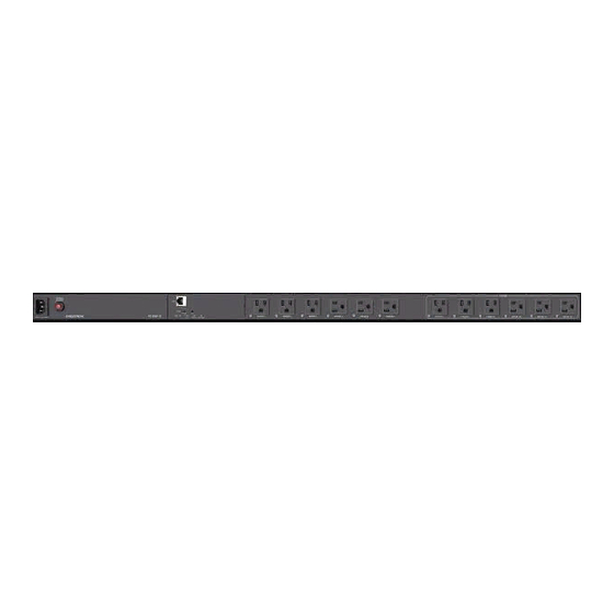
PC-350V-12 and PC-350V-18
Vertical Networked Power Controller & Conditioner with Surge Protection and Metering
The PC-350V-12 and PC-350V-18 are vertical rack-mountable power
controllers. They provide 120VAC power distribution, switching, surge
protection, noise filtering, and energy monitoring for Crestron® control
systems, AV systems, computers, and other equipment.
In the Box
1
PC-350V-12 or PC-350V-18
Additional Items
1
Power cord, 9.8 ft (3 m)
2
Mounting brackets
4
Mounting screws
Install the Device
Rack Mounting Safety Precautions
Elevated Operating Ambient Temperature: If installed in a closed or
multi-unit rack assembly, the operating ambient temperature of the
rack environment may be greater than room ambient temperature.
Therefore, consideration should be given to installing the equipment in
an environment compatible with the maximum ambient temperature
(Tma) specified by the manufacturer.
Reduced Airflow: Installation of the equipment in a rack should be such
that the amount of airflow required for safe operation of the equipment
is not compromised.
Mechanical Loading: Mounting of the equipment in the rack should be
such that a hazardous condition is not achieved due to uneven
mechanical loading.
Circuit Overloading: Consideration should be given to the connection of
the equipment to the supply circuit and the effect that overloading of
the circuits might have on overcurrent protection and supply wiring.
Appropriate consideration of equipment nameplate ratings should be
used when addressing this concern.
Reliable Earthing: Reliable earthing of rack-mounted equipment should
be maintained. Particular attention should be given to supply
connections other than direct connections to the branch circuit (e.g., use
of power strips).
Quick Start
1
Advertisement

Subscribe to Our Youtube Channel
Related Manuals for Crestron PC-350V-12


Summary of Contents for Crestron PC-350V-12
- Page 1 Quick Start PC-350V-12 and PC-350V-18 Vertical Networked Power Controller & Conditioner with Surge Protection and Metering The PC-350V-12 and PC-350V-18 are vertical rack-mountable power controllers. They provide 120VAC power distribution, switching, surge Install the Device protection, noise filtering, and energy monitoring for Crestron® control systems, AV systems, computers, and other equipment.
- Page 2 For toolless mounting, the rack must have keyhole slots on the rack frame or accessory channels with keyhole slots. Mounting the Device With Keyhole Mounts Mounting the Device Without Keyhole Mounts NOTE: Unless otherwise indicated in this guide, the installation procedure is the same for PC-350V-12 and PC-350V-18.
- Page 3 As shown below, this distance for PC-350V-12 and PC-350V-18 is 24.49 in. (622 mm) and 36.73 in. (933 mm), respectively. Distance between keyhole mounts for PC-350V-12 and PC-350V-18 Brackets can be attached to the rack angle using one of the following three methods.
- Page 4 Quick Start PC-350V-12 and PC-350V-18 Vertical Networked Power Controller & Conditioner with Surge Protection and Metering Method 1 Mounting the device onto the brackets Attaching brackets to the rack angle...
- Page 5 Quick Start PC-350V-12 and PC-350V-18 Vertical Networked Power Controller & Conditioner with Surge Protection and Metering Method 2 Mounting the device onto the brackets Attaching brackets to the rack angle...
- Page 6 Quick Start PC-350V-12 and PC-350V-18 Vertical Networked Power Controller & Conditioner with Surge Protection and Metering Method 3 Mounting the device onto the brackets Attaching brackets to the rack angle...
- Page 7 Quick Start PC-350V-12 and PC-350V-18 Vertical Networked Power Controller & Conditioner with Surge Protection and Metering Mounting the Device Without Keyhole Mounts 1. Remove the screws and keyhole mounts from the device. 2. Store the keyhole mounts and screws for future use.
- Page 8 Quick Start PC-350V-12 and PC-350V-18 Vertical Networked Power Controller & Conditioner with Surge Protection and Metering Method 1 Attaching the assembly to the rack angle Attaching brackets to the power controller...
- Page 9 Quick Start PC-350V-12 and PC-350V-18 Vertical Networked Power Controller & Conditioner with Surge Protection and Metering Method 2 Attaching the assembly to the rack angle Attaching brackets to the power controller...
- Page 10 Quick Start PC-350V-12 and PC-350V-18 Vertical Networked Power Controller & Conditioner with Surge Protection and Metering Method 3 Attaching the assembly to the rack angle Attaching brackets to the power controller...
- Page 11 Quick Start PC-350V-12 and PC-350V-18 Vertical Networked Power Controller & Conditioner with Surge Protection and Metering Outlet Test Before making connections to the power controller, perform an outlet test to ensure that the outlet the power controller is plugged into is properly wired: 1.
-
Page 12: Quick Start
Vertical Networked Power Controller & Conditioner with Surge Protection and Metering Make Connections Make the necessary connections as called out in the following illustration. Connect power last. PC-350V-12 CAUTION: The PC-350V-12 must be plugged into a circuit that has a 20-amp or a 15-amp circuit breaker. - Page 13 Quick Start PC-350V-12 and PC-350V-18 Vertical Networked Power Controller & Conditioner with Surge Protection and Metering PC-350V-18 CAUTION: The PC-350V-18 must be plugged into a circuit that has a 20-amp or a 15-amp circuit breaker.
-
Page 14: Reset The Device
Quick Start PC-350V-12 and PC-350V-18 Vertical Networked Power Controller & Conditioner with Surge Protection and Metering Factory Restore 1. Ensure the device is powered on. Reset the Device 2. Press and hold the HW-R button for 15 seconds until all status LEDs... -
Page 15: Important Safety Instructions
Refer to the following table for information about the LED indicators on Use the web user interface, SIMPL programming, or the Crestron the device. Home™ setup application to configure and monitor various components of the PC-350V-12 or PC-350V-18. For more information, refer to the LED Indicator Color Meaning product manual of the device. - Page 16 Development Tools License Agreement. Crestron product operating system software is licensed to Crestron dealers, CSPs, and end-users under a separate End-User License www.crestron.com/model/6511513 Agreement. Both of these Agreements can be found on the Crestron website at www.crestron.com/legal/software_license_agreement. PC-350V-18 The product warranty can be found at www.crestron.com/warranty.
Need help?
Do you have a question about the PC-350V-12 and is the answer not in the manual?
Questions and answers