Table of Contents
Advertisement
Quick Links
Advertisement
Table of Contents

Related Manuals for Crestron PC-350V Series


Summary of Contents for Crestron PC-350V Series
- Page 1 PC-350V Series Power Controllers Product Manual Crestron Electronics, Inc.
-
Page 2: Method
Crestron, the Crestron logo, Crestron Toolbox, Crestron Home, and XiO Cloud are either trademarks or registered trademarks of Crestron Electronics, Inc. in the United States and/or other countries. Domotz is either a trademark or registered trademark of Domotz Ltd. in the United States and/or other countries. UL is either a trademark or registered trademark of Underwriters Laboratories, Inc. -
Page 3: Table Of Contents
Contents Overview Power Controller Features Power Conditioning Adjustable Turn On Delay Remote-Controllable Switched Outlets Energy Monitoring Ambient Temperature Sensing Ping Monitoring Scheduling Built-In Logging Remote Management & Control UL® 1449 Certified Physical Description Specifications Technical Specifications Dimension Drawings Installation Rack Mounting Safety Precautions Important Safety Instructions Toolless Mounting Mounting the Device With Keyhole Mounts... - Page 4 Upload Configuration Save Changes Revert Status Inlet & Outlets Device Network Control System Settings Outlet Controls System Setup Device Configuration Logs Security Current User Users Groups 802.1x Configuration Configure the Power Controller for 802.1X Authentication Connect to XiO Cloud Service Troubleshooting DHCP Reset Hardware Reset...
- Page 5 v • Contents Product Manual — Doc. 9212A...
-
Page 6: Overview
Overview The PC-350V series power controllers are vertical rack-mountable power controllers designed to occupy no rack space (zero RU). They provide 120VAC power distribution, switching, surge protection, noise filtering, and energy monitoring for Crestron® control systems, AV systems, computers, and other equipment. All individually-switched outlets are protected and monitored, including outlets with EMI and RFI noise filtering (labeled as FILTERED). -
Page 7: Power Controller Features
Built-in energy usage and event logging Easy setup and operation using the web UI Crestron® control system integration via Ethernet Remote management via XiO Cloud® service, Crestron Home™ OS, and Domotz™ solution Integration with a custom-programmed Crestron control system via SIMPL programming software... -
Page 8: Adjustable Turn On Delay
Startup delay is initiated by disconnecting the power controller from the power source and then reconnecting it. It can also be initiated remotely using the web UI, Crestron Home, XiO Cloud, or Domotz. Cycle Delay — Up to 300 seconds of delay can be set between the turn off and turn on of an individual outlet. -
Page 9: Ping Monitoring
Crestron control system via Ethernet to enable control and monitoring through a touch screen, handheld remote, or mobile device. UL® 1449 Certified Surge protection for PC-350V series power controllers has been tested and certified by UL as compliant with the UL 1449 safety and performance standard for surge protective devices (SPD). -
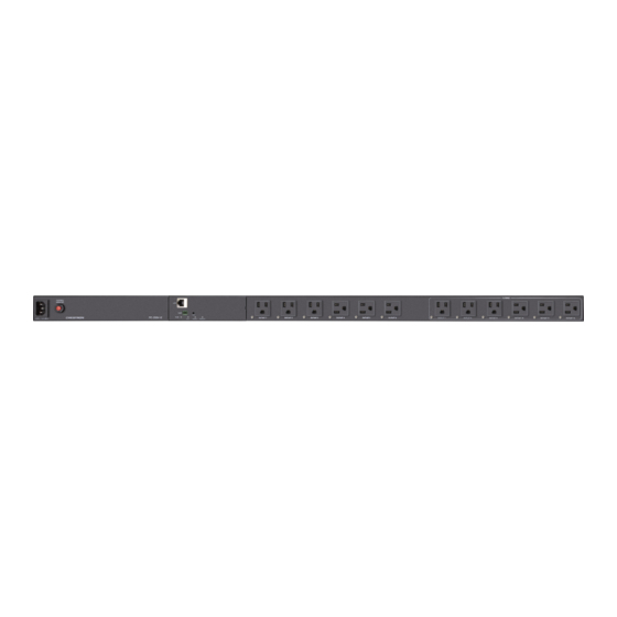
Page 10: Physical Description
Physical Description PC-350V-12 PC-350V-18 POWER INLET: (1) 100-120VAC~50/60Hz, mates with removable power ❶ cord (included) THERMAL BREAKER: Disconnects power to all outlets in case of an ❷ overload condition, press to reset after overload condition is resolved LAN: 8-pin RJ-45 connector, female; ❸... - Page 11 "Identify" search process is initiated for the unit in the Crestron Home™ app FAULT LED: (1) Red LED, indicates any of the following fault conditions: ❾...
-
Page 12: Specifications
Specifications This section provides the following information: Technical Specifications (below) Dimension Drawings (on page 15) Technical Specifications Power Conditioner Maximum Output 12A @ 120VAC Current, Total: Maximum Output 12A @ 120VAC (subject to a maximum total output current of 12A for all outlets Current, Per Outlet: combined) Filtration for the... - Page 13 Communications Ethernet 10/100 Mbps, auto-switching, auto-negotiating, auto-discovery, full/half duplex, TCP/IP, UDP/IP, CIP, DHCP, SSL, TLS, SNMP, web server, web UI setup and control, Crestron control system integration, XiO Cloud monitoring Connectors 120V~ 12A 60Hz: Detachable 9.8 ft (3 m) grounded AC power cord with NEMA 5-15P...
- Page 14 Ethernet activity Per Outlet Indicator: (1) Green LED: Illuminates when outlet is turned on blinks when the "Identify" search process is initiated for the device in the Crestron Home app Environmental Temperature: 32° to 104°F (0° to 40°C) Humidity:...
-
Page 15: Dimension Drawings
Dimension Drawings PC-350V-12 PC-350V-18 15 • PC-350V-12 and PC-350V-18 Product Manual — Doc. 9212A... -
Page 16: Installation
Installation Follow the below safety instructions for safe installation and operation of the power controller. Rack Mounting Safety Precautions Elevated Operating Ambient Temperature: If installed in a closed or multi-unit rack assembly, the operating ambient temperature of the rack environment may be greater than room ambient temperature. -
Page 17: Important Safety Instructions
Important Safety Instructions Installation must be completed by a professional. Equipotential bonding must be in place where the equipment is mounted. The power cord must be connected to an outlet with a properly earthed ground connection, as the device is earthed through the power cord connection at the inlet. WARNING: The device power plug is designed to be inserted into a NEMA 5-15 (three- prong grounded) outlet only. -
Page 18: Toolless Mounting
The power controller can be mounted vertically into a rack occupying no rack space (Zero RU). Use one of the following procedures to mount the power controller into a rack. Toolless Mounting (below) NOTE: For toolless mounting, the rack must have keyhole slots on the rack frame or accessory channels with keyhole slots. -
Page 19: Mounting The Device With Keyhole Mounts
Mounting the Device With Keyhole Mounts 1. Use the rack mounting screws (not included) and washers (not included) to attach the two included brackets to the rack angle. When attaching the brackets to the rack angle, ensure that the distance between the bracket keyholes is aligned with the distance between keyhole mounts on the rear of the device. -
Page 20: Method 1
Method 1 Attaching brackets to the rack angle Mounting the device onto the brackets Product Manual — Doc. 9212A PC-350V-12 and PC-350V-18 • 20... - Page 21 Method 2 Attaching brackets to the rack angle Mounting the device onto the brackets 21 • PC-350V-12 and PC-350V-18 Product Manual — Doc. 9212A...
-
Page 22: Method 3
Method 3 Attaching brackets to the rack angle Mounting the device onto the brackets Product Manual — Doc. 9212A PC-350V-12 and PC-350V-18 • 22... -
Page 23: Mounting The Device Without Keyhole Mounts
Mounting the Device Without Keyhole Mounts 1. Remove the screws and keyhole mounts from the device. 2. Store the keyhole mounts and screws for future use. 3. Use the four included mounting screws to attach the two included brackets to the rear of the device. -
Page 24: Method 1
Method 1 Attaching brackets to the power controller Attaching the assembly to the rack angle Product Manual — Doc. 9212A PC-350V-12 and PC-350V-18 • 24... -
Page 25: Method 2
Method 2 Attaching brackets to the power controller Attaching the assembly to the rack angle 25 • PC-350V-12 and PC-350V-18 Product Manual — Doc. 9212A... -
Page 26: Method 3
Method 3 Attaching brackets to the power controller Attaching the assembly to the rack angle Product Manual — Doc. 9212A PC-350V-12 and PC-350V-18 • 26... -
Page 27: Outlet Test
If the FAULT LED lights, then the connected outlet is not wired correctly. Fault details can be viewed in the device web user interface. For more information on monitoring and configuring the device parameters, refer to the PC-350V Series Product Manual. NOTE: Do not make any connections to the device until the connected outlet is wired correctly. -
Page 28: Make Connections
Make Connections Make the necessary connections as called out in the following illustration. Connect power last. PC-350V-12 PC-350V-18 CAUTION: The power controller must be plugged into a circuit that has at least a 20-amp or a 15-amp circuit breaker. Product Manual — Doc. 9212A PC-350V-12 and PC-350V-18 •... -
Page 29: Configuration
To access the web user interface: 1. Connect the device to the same network as the host computer. 2. Use the Device Discovery Tool in the Crestron Toolbox™ software to discover the power controller. The power controller appears with its IP address. - Page 30 5. If you are creating a user account for the first time, do the following; otherwise, skip to step 3. a. Enter a username in the Username field. b. Enter a password in the Password field. c. Re-enter the same password in the Confirm Password field. d.
- Page 31 8. Click Sign In. The web user interface is displayed. The web user interface displays the Sign Out button ( ), Action drop-down menu, and the following tabs: Status: Used to monitor device status Settings: Used to configure device settings Logs: Used to view or export the device activity logs Security: Used to enable authentication and other security settings 802.1x Configuration: Used to configure IEEE 802.1x network authentication for the device security...
-
Page 32: Action
Action The Action drop-down menu is displayed at the top right side of the interface and provides quick access to common device functionalities, such as: Reboot Restore Update Firmware Download Logs Manage Certificates Download Configuration Upload Configuration Save Changes Revert Once changes have been made to the power controller configuration, the Action button changes to the Save Changes button. -
Page 33: Restore
Auto Update (on page 45). 1. Visit www.crestron.com/firmware and download the latest PUF (package update file). 2. Click Update Firmware. The Firmware Upgrade dialog box is displayed. 3. Click Browse, and then navigate to the firmware PUF on the host computer. -
Page 34: Manage Certificates
Manage Certificates Click Manage Certificates in the Action drop-down menu to add, remove and manage certificates used in 802.1x and other protected networks. The following certificate tabs are displayed: Root: The Root certificate is used by the power controller to validate the network's authentication server. -
Page 35: Download Configuration
3. Navigate to the CA file on the host computer. 4. Select the CA file, and then click Open. 5. Click Load to load the CA file to the power controller. The upload progress is shown in the dialog box. 6. -
Page 36: Upload Configuration
Upload Configuration 1. Click Upload Configuration to load the saved configuration file to the power controller. The Device Configuration dialog box is displayed. 2. Click Browse, and then navigate to the compressed .tgz file on the host computer. 3. Select the file, and then click Open. 4. -
Page 37: Status
Status The Status tab is the default tab that displays after login. The Status screen displays information about the device and its other operating parameters. Click on a selection name to expand the selection. If the selection is expanded, click the selection name again to collapse the section. - Page 38 Input Voltage (V): Displays the input voltage level in volts Total Current (A): Displays the combined current level of all outlets in amperes Total Power (W): Displays the combined power in watts Click the + (plus) icon next to Protection to display the following information: Wiring: Reports whether there is a fault in the power conditioner wiring Surge Protection: Reports whether a power surge has been detected Over Voltage: Reports whether the voltage level on the AC input is over the set limit...
-
Page 39: Device
Outlet Number: Displays the outlet number that corresponds with the outlet on the power controller Outlet Name: Displays the outlet name Fault Status: Reports whether there is a fault on that particular outlet Status: Displays the power status of outlet Energy (Wh): Displays the total accumulated energy in kilowatt hours Power (W): Displays the instantaneous power in watts Current (A): Displays the instantaneous current in amperes... -
Page 40: Network
Firmware Version: The firmware version loaded onto the power controller Click + More details at the bottom of the Device tab to display an expanded section that shows additional power controller information. If + More Details is selected, click - Less details to collapse the section. -
Page 41: Control System
IP Address/Hostname: The control system IP address or hostname Room ID: The control system room ID that the power controller is associated with (for connections to the Crestron Virtual Control server-based control system) Status: The control system connection status 41 • PC-350V-12 and PC-350V-18... -
Page 42: Settings
Settings The Settings tab enables you to configure the power controller settings. The Settings page can be accessed at any time by clicking the Settings tab of the power controller interface. Information displayed on the Settings tab is organized into different sections. Outlet Controls Use the Outlet Controls drop-down menu to configure and view outlet parameters. -
Page 43: System Setup
Supported Actions: Provides options in a drop-down list to configure the outlets for On/Off/Power Cycle and Power Cycle Only. When selecting On/Off/Power Cycle, the On, Off, and Power Cycle buttons remain enabled. When selecting Power Cycle Only, the On and Off buttons get disabled. Clear Energy Usage: Clears the accumulated energy readings for all outlets. - Page 44 Network The Network drop-down menu displays network-related information about the power controller, including the Host Name, Domain, Primary Static DNS, and Secondary Static DNS. NOTE: By default, the host name of the power controller consists of the model name followed by the MAC address of the device.
- Page 45 2. Define the URL to download the updates by doing either of the following: a. Use the default URL to download the updates from the Crestron server. b. If Custom URL Path is turned on, enter the custom URL path for the update server.
- Page 46 a. Select the desired Day of Week and Time of Day (24-hour format) values. b. Set the Poll Interval by entering a value from 60 to 65535 minutes. A value of 0 disables the Poll Interval. 4. Click Save Changes. Clicking Update Now causes the firmware to be updated at the current time;...
-
Page 47: Device Configuration
To encrypt the connection: 1. Set the Encrypt Connection slider to enabled (right) 2. Enter the username in the Control System Username field. 3. Enter the password in the Control System Password field. 4. Enter the Room ID in the Room ID field. 5. - Page 48 Schedule #: Displays the schedule number. Name: Displays the schedule name to identify the specific scheduled event. Outlets: Displays the included outlets for the corresponding schedule. Frequency: Displays the frequency (Once, Daily, Weekly, Bi-Weekly, or Monthly) of the schedule. Enabled: Displays the status of the schedule. Move the Enabled slider to the right to enable the schedule.
- Page 49 Frequency: Select Once, Daily, Weekly, Bi-Weekly, or Monthly, and then enter values in the corresponding fields to enable the power controller to execute the schedule event. Once: Click the up and down arrow buttons or enter the values in Day of Month, Month, Year, Hours, and Minutes manually.
- Page 50 Bi-Weekly: Click the up and down arrow buttons or enter the values manually in Day of Week, Hours and Minutes fields. Monthly: Click the up and down arrow buttons or enter the values manually in Day of Month, Hours and Minutes fields. Outlets: Each schedule can include one or more outlets to perform the desired actions (On, Off, or Cycle) listed in the Actions column.
- Page 51 Over voltage cutoff: Click the up and down arrow buttons or enter the over voltage cutoff limit manually. Temperature Probe The power controller sends alert notifications through a Crestron Control Processor if the temperature is detected over the set threshold values. Temperature Warning: Move the slider to enable the setting to receive temperature warnings.
- Page 52 Use the following settings to create a rule for the desired outlets: Rule Number: Displays the rule number for ping monitoring. A maximum of 20 rules can be applied. Target Outlet: Select one or more target outlets from the drop-down list to apply the defined rule.
- Page 53 Ping Interval (minutes): Enter the time interval between ping retry attempts in minutes. The valid time range is 1-60 minutes. Power Up Wait Time (minutes): Click the up and down arrow buttons or enter the Power Up Wait Time (minutes) limit manually to set the amount of time the power controller will wait to start pinging the target address(es) after power cycling the target outlet(s).
-
Page 54: Logs
Logs The Logs tab enables you to view and download the power controller activity logs. The activity logs download as .csv or pdf file to the host computer. The Filters feature allows you to view and download the activity logs for the desired period. Select the different day and time options available: a. -
Page 55: Security
Security Click the Security tab to configure security for users and groups and to allow different levels of access to the power controller functions. By default, security is disabled. Select Encrypt and Validation, Encrypt, or OFF in the SSL Mode drop-down menu, to specify whether to use encryption. -
Page 56: Users
3. Click OK to save or click Cancel to cancel the changes. Users Click the Users tab to view and edit user settings. The Users tab can be used to add or remove local and Active Directory users and preview information about users. Use the Search Users field to enter search term(s) and display users that match the search criteria. - Page 57 Create a New Local User 1. Click the Create User button in the User tab. 2. In the Create User dialog, enter the following: a. Enter a user name in the Name field. A valid user name can consist of alphanumeric characters (letters a-z, A-Z, numbers 0-9) and the underscore “_”...
- Page 58 a. Enter a user name in the Name field in the format “Domain\UserName”, for example “Users\test”. Valid user names can contain alphanumeric characters (letters a-z, A-Z, numbers 0-9) and the underscore “_” character. b. Move the Active Directory User slider to enabled. c.
- Page 59 Update User Details 1. Click the edit button ( ) in the Actions column to update information for the selected user. 2. Enter a password in the Password field; re-enter the same password in the Confirm Password field. 3. Select one or more groups to assign the user to from the Groups drop-down list. 4.
-
Page 60: Groups
Groups Click the Groups tab to view and edit group settings. The Groups tab can be used to add local and Active Directory groups, remove local and Active Directory groups, and preview information about a group. Use the Search Groups field to enter search term(s) and display groups that match the search criteria. - Page 61 Create Local Group 1. Click the Create Group button. 2. In the Create Group dialog, enter the following: a. Enter the group name in the Name field. b. Assign the group access level by selecting a predefined access level (Administrator, Connect, Operator, Programmer, User) from the Access Level drop-down list.
- Page 62 3. Assign the group access level by selecting a predefined access level (Administrator, Connect, Operator, Programmer, User) from the Access Level drop-down list. 4. Move the Active Directory Group slider to enabled. 5. Click OK to save. Click Cancel to cancel the changes. Delete a Group Click the trashcan button ( ) in the Actions column to delete a group.
-
Page 63: 802.1X Configuration
802.1x Configuration The power controller has built-in support for the 802.1X standard (an IEEE network standard designed to enhance the security of wireless and Ethernet LANs. The standard relies on the exchange of messages between the device and the network's host, or authentication server), allowing communication with the authentication server and access to protected corporate networks. - Page 64 Select EAP-MSCHAP V2 Password, enter the username and password supplied by the network administrator into the Username and Password fields. This method does not require the use of a machine certificate, only the user name and password credentials. 4. If you enabled the Enable Authentication Server Validation option, this will enable the Select Trusted Certificate Authoritie(s) list box which contains signed Trusted Certificate Authorities (CAs) preloaded into the power controller.
-
Page 65: Connect To Xio Cloud Service
XiO Cloud® service allows supported devices across an enterprise to be managed and configured from one central and secure location in the cloud. Supported Crestron® devices are configured to connect to the service out of the box. Use of the service requires a registered XiO Cloud account. To register for an XiO Cloud account,... -
Page 66: Troubleshooting
Troubleshooting A DHCP reset, hardware reset, factory restore, or power cycling all outlets may be performed when troubleshooting. DHCP Reset 1. Ensure the device is powered on. 2. Press and hold the HW-R button for 1 second and release it for less than 2 seconds. 3. -
Page 67: Power Cycle All Outlets
Power Cycle All Outlets 1. Ensure the device is powered on. 2. Tap the HW-R button for less than 1 second. The power cycling initiates for all outlets. 67 • PC-350V-12 and PC-350V-18 Product Manual — Doc. 9212A... - Page 68 This page is intentionally left blank. Product Manual — Doc. 9212A PC-350V-12 and PC-350V-18 • 68...
- Page 69 Product Manual — Doc. 9212A Crestron Electronics, Inc. 15 Volvo Drive, Rockleigh, NJ 07647 12/21/21 Tel: 888.CRESTRON Specifications subject to Fax: 201.767.7656 change without notice. www.crestron.com...
Need help?
Do you have a question about the PC-350V Series and is the answer not in the manual?
Questions and answers