Advertisement
Quick Links
DO
GUIDE
BPC(I)-8
onCue
Basic Presentation Controller
®
DO
Install the Device
NOTE: The BPC-8 and BPCI-8 are functionally similar. For simplicity within this guide, the term
"BPC-8" is used except where noted.
The hardware supplied with the BPC-8 is listed in the DO Check the Box table.
The following tools are required for installation of a BPC-8:
1. Phillips screwdriver (not included)
2. Two #6-32 x 1" pan head Phillips screws (included)
3. Two 4-pin detachable terminal block connectors (included)
Install a Conductor Cable
Install a 4-conductor cable (minimum 24 AWG) with 50ft (~15m) maximum length (not included)
between a 1-gang electrical box for the BPC-8 and the location of the BMP-8-IMC interface
module.
Refer to the pin connections shown in the installation diagram below and connect the supplied
4-pin detachable connectors to each end of the cable.
Mount the BPC-8 into an Electrical Box
Connect the preinstalled cable to the 4-pin terminal block on the rear of the button assembly,
and then mount the BPC-8 to a 1-gang electrical box as shown in the following diagram.
1-gang electrical box
(2.5 in (~63 mm) depth
recommended)
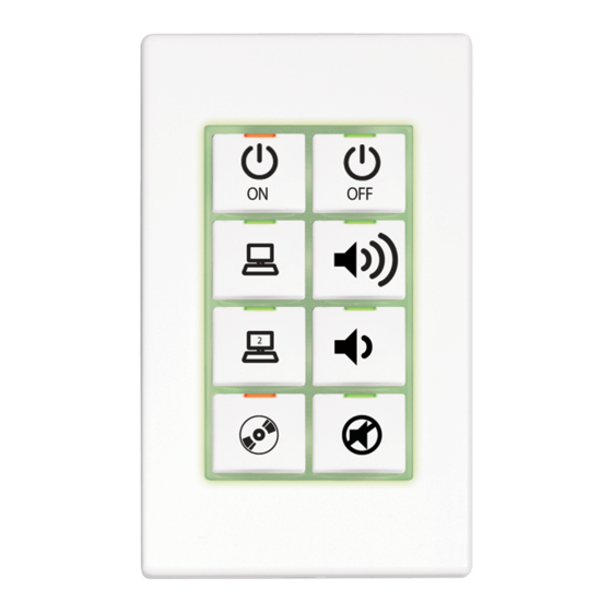
Button assembly
LED
indicators
Interchangeable
Faceplate
button caps
Button support
grid
6-32x1"
pan head screws
LED window
Grid stabilizing tabs
B PC- 8-IMC
12 T R G
Optical cable access port
CBL-PWR-CTRL-P-TL-50
cable or equivalent
12: Power (12 Vdc)
T:
Data
R : Data
G: Ground
DO
Check the Box
QTY PRODUCT
1
Button Assembly
1
Module, Interface
1
Emitter Probe, IR, Crestron STRIP
1
Fastener, Dual Lock, 2.5" x 1"
2
Connector, 4-Pin
2
Screw, 6-32 x 1", Pan Head, Phillips
BPC-8 Only
1
Power Pack, 12 Vdc 0.5 A, 100-240 Vac
BPCI-8 Only
1
Power Pack, 12 Vdc 0.5 A, 120-240 Vac
1
Bracket, Mounting, Single Gang
1. Remove the faceplate by snapping it off the button assembly.
NOTE: Use care when removing the faceplate, as it holds the button support grid and
button caps in place.
2. Ensure the button unit is oriented with the arrow at the top, and then insert the unit into the
electrical box and attach it using the supplied #6-32 x 1" screws.
3. Return the button caps to their original positions on the button assembly with LED windows
oriented upward to match each LED indicator.
4. Install the button support grid with stabilizing tabs to the rear, put the faceplate in position
(optical cable access port on the lower right), and snap it into place.
Mount the BPC-8-IMC
Mount the BPC-8-IMC onto an appropriate surface at the display location using the supplied
hook and loop tape.
DO
Connect the Device
Make connections to the BPC-8 using Crestron
power after all connections have been made.
Connect the BPC-8
Access port: For optical cable from BPC-HLPIR
BPC-8-IMC:Power and control signals to/from
IR learner and programmer (optional)
COLOR
PART NUM.
4512112
4511874
Black
2001137
2005414
2003576
2007251
2045853
2045884
2030802
power supplies for Crestron equipment. Apply
®
B PC- 8-IMC
12 T R G
BPC-8-IMC interface module (included)
Advertisement

Related Manuals for Crestron onCue BPC-8


Summary of Contents for Crestron onCue BPC-8
- Page 1 Mount the BPC-8-IMC onto an appropriate surface at the display location using the supplied (2.5 in (~63 mm) depth hook and loop tape. recommended) Connect the Device Button assembly Make connections to the BPC-8 using Crestron power supplies for Crestron equipment. Apply ® power after all connections have been made. indicators Interchangeable...
- Page 2 This equipment generates, uses and can radiate radio frequency energy and, if not installed and used in accordance with the registered trademarks, and trade names may be used in this document to refer to either the entities claiming the marks and names or their products. Crestron disclaims any proprietary interest in the marks and names of others.
Need help?
Do you have a question about the onCue BPC-8 and is the answer not in the manual?
Questions and answers