
Related Manuals for ADTRAN Total Access 300


Summary of Contents for ADTRAN Total Access 300
- Page 1 ® Total Access 300 2 POTS, 2 GigE ONT Installation and Maintenance Practice Document Number: 61187602G2-5A CLEI: BVM56P10A_ _ June 2008...
- Page 2 In no event will ADTRAN be liable for any special, incidental, or consequential damages or for commercial losses even if ADTRAN has been advised thereof as a result of issue of this document.
- Page 3 Revision History Revision Date Description June 2008 This is the initial release. Conventions The following typographical conventions are used in this document: This font indicates a cross-reference link. indicates screen menus, fields, and parameters. This font indicates keyboard keys ( ).
- Page 4 Total Access 300 2 POTS, 2 GigE ONT Installation and Maintenance Practice Training ADTRAN offers training courses on our products. These courses include overviews on product features and functions while covering applications of ADTRAN product lines. ADTRAN provides a variety of training options, including customized training and courses taught at our facilities or at customer sites.
-
Page 5: Table Of Contents
Contents General ................. . 1 Description. - Page 6 Total Access 300 2 POTS, 2 GigE ONT Installation and Maintenance Practice Alternative Grounding Method ............28 Local Power Source Wire Run .
- Page 7 ADTRAN Technical Support ........
- Page 8 Total Access 300 2 POTS, 2 GigE ONT Installation and Maintenance Practice Tables Table 1. IDC Connector Pinout ............31 Table 2.
-
Page 9: General
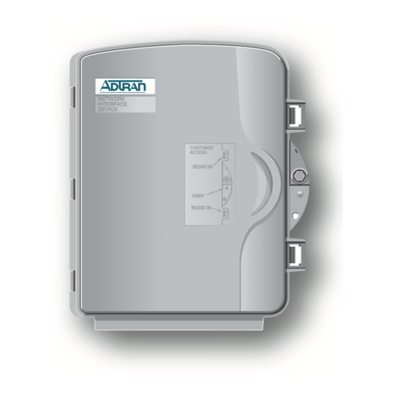
Total Access 300 2 POTS, 2 GigE ONT GENERAL This practice is an installation and maintenance guide for the ADTRAN Total Access 300 ® Gigabit Passive Optical Network (GPON) Single Family Unit (SFU) Optical Network Terminal (ONT). Figure 1 illustrates the ONT (P/N 1187602G2) front panel. -
Page 10: Description
2 POTS, 2 GigE ONT Installation and Maintenance Practice Description GPON technology provides a consistent and common approach to advancing the public communications network using: • Traditional telephone services (Plain Old Telephone Service (POTS)) • High speed data services • Video services (CATV overlay or video over IP). The GPON network consists of an Optical Line Terminal (OLT) located at the central office and a set of Optical Network Terminals (ONTs) located at the customer’s premises. -
Page 11: Features
Installation In the upstream direction transmission of data must be coordinated between each ONT to avoid collisions due to the shared media of the optical distribution network (ODN). Data is transmitted according to control mechanisms configured in the OLT. The aggregate upstream rate is 1.25 Gbps. -
Page 12: Compliance
1. This device may not cause harmful interference. 2. This device must accept any interference received, including interference that may cause undesired operation. Changes or modifications not expressly approved by ADTRAN could void the user’s authority to operate this equipment. CAUTION This equipment must be connected to a known, reliable earth ground at all times during installation and service. -
Page 13: Components And Interfaces
OSP wiring. NOTE The Total Access 300 2 POTS, 2 GigE ONT (1187602G2) is designed to operate with nominal operating voltage of 12Vdc and minimum operating voltage of 10.5Vdc. COMPONENTS AND INTERFACES The ONT consists of the following components and interfaces: •... -
Page 14: Mechanical Components
2 POTS, 2 GigE ONT Installation and Maintenance Practice Mechanical Components The ONT is designed for outdoor applications. The mechanical design uses a “box-in-box” concept such that the Outer Enclosure provides a second level of enclosure for the Inner Enclosure. Outer Enclosure The outer enclosure provides both environmental control (weatherproofing) and access control and consists of the following components:... -
Page 15: Outer Enclosure Door/Cover
Installation Outer Enclosure Door/Cover The enclosure is intended for use on the outside of a building and is designed to meet US environmental requirements. The unit is weather hardened and is able to withstand 70 m.p.h. wind driven rain, high temperature, cold temperature, drop tests and all other GR-49, GR-950, and GR-487 requirements. -
Page 16: Outer Enclosure Security Locking Feature
2 POTS, 2 GigE ONT Installation and Maintenance Practice Outer Enclosure Security Locking Feature The Outer Enclosure Door has a double security locking feature provided by the third molded part (see Figure 4). This provides the following capabilities: • End-user can secure the door closed with a Phillips head screw. •... -
Page 17: Inner Enclosure
Installation Inner Enclosure The Inner Enclosure (see Figure 5) is designed for insertions into the Outer Enclosure for use in outdoor applications. Figure 5. Inner Enclosure The Inner enclosure is a single unit containing four molded parts, a circuit board and miscel- laneous fasteners. -
Page 18: Molded Cover
2 POTS, 2 GigE ONT Installation and Maintenance Practice Molded Cover The cover (see Figure 6) includes the following features: • Fiber slack loop holder • Splice holder. • Molded fiber cover Fiber Slack Loop Holder Molded Fiber Cover Fiber Splice Holder Fiber Slack Loop Holder Figure 6. -
Page 19: Molded Fiber Cover
Installation Molded Fiber Cover The Molded Fiber Cover (see Figure 7) provides mechanical protection for the optical fiber pigtail and adaptor. In the figure below, the Molded Cover has been removed to expose the SC connector and adaptor. The safety warning label for the laser Class type is attached to the cover as shown. -
Page 20: Telco Access Door
2 POTS, 2 GigE ONT Installation and Maintenance Practice Telco Access Door Separation of the Telco and subscriber areas is provided by an internal door (see Figure 8). It is molded of fire retardant poly-carbonate and is color matched to the base. Opening this door provides access to the fiber and power connections. -
Page 21: Circuit Board
Installation Circuit Board The ONT contains a single electronics board that provides the following functions: • “Data Processing” • “Voice Processing” • “Alarm Reporting” Data Processing The following data processing functions are supported by the ONT: • Ethernet bridging/switching as per IEEE 802.1D/802.1Q •... -
Page 22: Alarm Reporting
2 POTS, 2 GigE ONT Installation and Maintenance Practice • RTP/RTCP • Silence suppression • Comfort noise generation • H.248 • SIP • CLASS features (SIP & H.248) • RFC 2833 • Voice activity detection • DHCP • Configurable framing size - 10 ms, 20 ms, or 30 ms •... -
Page 23: Ont Interfaces
Installation ONT Interfaces The ONT supports the following interfaces: • “GPON Interface” • “Ethernet Interface” • “POTS Interface” • “Power” GPON Interface The GPON interface consists of a diplexer device for optical to electrical conversion. It supports 1.25 Gbps GPON application as per ITU-T G.984.2 specification. Capabilities are: •... -
Page 24: Power
2 POTS, 2 GigE ONT Installation and Maintenance Practice • Suppression of spurious off hook signals • Integrated ringing • AC power cross detection • Reverse line feed option • Low current standby mode • µ-law or a-law voice coding •... -
Page 25: Ups Power Supply
Installation UPS Power Supply The ONT utilizes an uninterruptible power supply (UPS). An UPS (see Figure 9) is a battery backup system designed to continue providing power when the primary power source is lost. When the UPS senses a loss of power from the primary source, the backup battery is activated to provide power for a short period of time. -
Page 26: Installation
Ethernet ports for usability. 3. Examine the power supply to ensure that the UPS, battery and power cord are present and sound. If damage has occurred, file a claim with the carrier then contact ADTRAN Customer Service. Refer to “Appendix A, Warranty”... -
Page 27: Required Tools
Installation Required Tools Standard technician tools are used for a ONT installation (for example, drill, drill bits, side cutters, screwdrivers, nut drivers, hex wrenches, wire strippers, side cutters, etc.). Additionally, the following tools maybe required for the installation of the ONT: •... -
Page 28: Instructions For Installing The Sfu Ont
2 POTS, 2 GigE ONT Installation and Maintenance Practice Instructions for Installing the SFU ONT A typical ONT installation with UPS is shown in Figure Customer provided premises wiring including CAT5 or higher Ethernet cable and POTS twisted pair to be terminated in the ONT by technician Communications... -
Page 29: Determining Ont Enclosure Location
Installation CAUTION This equipment must be connected to a known, good, earth ground at all times during installation and service. Refer to the National Electrical Code (NEC) and state/local codes for details on grounding requirements. CAUTION This equipment must be serviced by authorized service personnel only. -
Page 30: Remove Inner Box From Outer Enclosure
2 POTS, 2 GigE ONT Installation and Maintenance Practice Remove Inner Box from Outer Enclosure The ONT consists of an external enclosure to provide environmental protection and an internal electrical module. The inner and outer boxes must be separated prior to installation. Refer to Figure 11 complete the following steps: 1. -
Page 31: Mounting The Enclosure
Installation Mounting the Enclosure Use a maximum of a #10 screw to fit properly in the diameter of the mounting holes (see Figure 12). Make sure to leave a minimum clearance of 2 inches from the hinges for opening the door. Complete the following steps to mount the enclosure: 1. -
Page 32: Wire Routes And Pre-Terminating The Outer Enclosure
2 POTS, 2 GigE ONT Installation and Maintenance Practice Wire Routes and Pre-Terminating the Outer Enclosure Figure 13 shows the Outer Enclosure with all of the connections pre-cut to proper length, pre- terminated with the appropriate connectors, and inserted into their appropriate place holders. The following sections describe these pre-termination procedures which, when completed, enables the ONT Inner Module to be installed at a later time. -
Page 33: Fiber Drop Cable Route
Installation Fiber Drop Cable Route WARNING Do not look into the ends of optical fibers. Exposure to invisible LASER radiation may cause serious retinal damage or even blindness. Verify the optical source is disabled through the use of an optical power meter before handling optical fibers. CAUTION Use caution when routing wires and cables. -
Page 34: Figure 15. Bulk Head Adapter
2 POTS, 2 GigE ONT Installation and Maintenance Practice Figure 15. Bulk Head Adapter NOTE The connector termination type - SC/APC (Green) or SC/PC (Blue) depends on the ONT type. In all cases route a tie-wrap through the cut-out in the cable clamp at the bottom of the ONT. Place the fiber drop cable in the channel of the rubber grommet and secure it to the cable clamp with the tie wrap (see Figure... -
Page 35: Grounding The Buried Fiber
Installation Grounding the Buried Fiber The buried fiber drop Cable to the subscriber’s premises used in this application can be one of the following: • Non-armored: The non-armored fiber drop cable has a metal strand for locating purposes. Skip this procedure if the fiber drop is the a non-armored fiber type. •... -
Page 36: Alternative Grounding Method
2 POTS, 2 GigE ONT Installation and Maintenance Practice 3. Attach the #6 ground to the side of the subscriber’s premises with stainless steel half moon clamps or tie-wrap the ground to the riser conduit of the buried fiber cable drop. When using tie-wraps wait until the Local Power Source (LPS) wire run has been installed and tie-wrap both the #6 ground and the LPS wire run to the riser conduit of the Buried Fiber drop. -
Page 37: Local Power Source Wire Run
Installation Local Power Source Wire Run WARNING Before making any power connections to this equipment, verify the power is off (fuse removed/breaker tripped). WARNING This equipment should only be operated from the type of certified/ listed power supply recommended by the manufacturer. CAUTION Use caution when routing wires and cables. -
Page 38: Figure 18. Local Power Source Installation
2 POTS, 2 GigE ONT Installation and Maintenance Practice Power and Alarm leads require a jacketed, 4 pair wire of the proper gauge. Wire run via Customer provided PVC conduit or per local practice. UPS with battery backup installed by technician Riser conduit for fiber drop cable GFI/non-GFI outlet - highly... -
Page 39: Ont Power Connector
Installation ONT Power Connector The ONT is provided with a 7 conductor Insulation Displacement Connection (IDC) connector (see Figure 19). The IDC connector is typically green and provides connections for the 7 conductors from the LPS wire run. The IDC connector is color coded and should be terminated according to the pinout in Table The maximum length of the DC drop is determined by the gauge of the power wire used. -
Page 40: Figure 20. Idc Connector - Inner Module
2 POTS, 2 GigE ONT Installation and Maintenance Practice Table 2. DC Drop Distance by Wire Gauge Wire Gauge Distance in Feet Distance in Meters 16 AWG 18 AWG 20 AWG 22 AWG To make connections from the LPS to the IDC connector complete the following steps: 1. -
Page 41: Figure 21. Idc Connector - Outer Enclosure
Installation 2. Place the IDC connector in the holder provided in the outer box (see Figure 21). The holder is located such that the wiring will be the correct length when the Inner Module is installed. IDC connector pre-terminated and seated in place-holder Tie-wrap powercable to entry on outer enclosure Figure 21. -
Page 42: Fiber Drop Cable Installation
2 POTS, 2 GigE ONT Installation and Maintenance Practice Fiber Drop Cable Installation A fiber connection is required between the inner ONT enclosure and the fiber termination point installed in the outer enclosure. This may be achieved by using the provided fiber patch cord. -
Page 43: Pots Connection
Installation POTS Connection Route the Subscriber POTS wires through the cable entry on the right side of the enclosure. To ease installation and maintenance, it is intended that the POTS wires are installed under the inner box. Two tie wrap points are provided for wire management (see Figure 23). -
Page 44: Ethernet Connection
2 POTS, 2 GigE ONT Installation and Maintenance Practice Ethernet Connection If the ONT is to support up to 1 Gigabit operation (10/100/1000) the cable used should be rated CAT-6. Strip back the jacket of the subscriber Ethernet cable and connect the 4 pair twisted wires to the RJ-45 Plug using a RJ-45 crimper. -
Page 45: Figure 24. Inner Module Installation
Installation less than 30mm (1.2 inches) radius or 60mm (~2.5 inches). When the maintenance door is closed it should not come in contact with the fiber. 7. Install the IDC Power/Alarm Connector into the base on the printed circuit board. SC/APC Connector Ground Screw... -
Page 46: Terminate Subscriber Services
2 POTS, 2 GigE ONT Installation and Maintenance Practice Terminate Subscriber Services Subscriber Services installation consists of the following: • “POTS Connections” on page 38 • “Ethernet Data Connections” on page 39 CAUTION Use caution when routing wires and cables. Avoid severe bending and routing over sharp edges. -
Page 47: Idc Connectors
Installation IDC Connectors If the IDC connectors are used the RJ-11 jacks provide a diagnostic test point. Inserting an RJ-11 jack (i.e., telephone cable or telephone test set) will connect the telephone set to the ONT and also disconnect the subscriber service from the ONT providing fault isolation to the SFU or premises wiring. -
Page 48: Figure 26. Ups Detail (Typical)
2 POTS, 2 GigE ONT Installation and Maintenance Practice WARNING This equipment should only be operated from the type of certified/ listed power supply supplied by the manufacturer with the equipment. NOTE When installing the UPS, refer to the manufacture’s directions as necessary. -
Page 49: Commissioning And Testing
Installation 9. Plug the UPS power cord into the wall outlet. (The UPS battery charges when it is connected to the utility power. The battery usually charges fully during the first 18 hours of normal operation. Do not expect full battery run capability during this initial charge period.) 10. -
Page 50: Front Panel Leds
2 POTS, 2 GigE ONT Installation and Maintenance Practice Front Panel LEDs The ONT provides front panel LEDs to display status information. The ONT LEDs and status descriptions are shown in Table Table 4. Front Panel LEDs Label Status Description No power: UPS disconnected or malfunctioning, PWR LED is bad, or defective LPS wiring Green... -
Page 51: Secure The Unit
(for example, a laptop computer) to verify the Ethernet link is active. Refer to the Total Access 300 GPON 2.5G 2-Port Access Module Installation and Maintenance Practice (P/N 61187500E1-5) for details on how to do this. -
Page 52: Troubleshooting
2 POTS, 2 GigE ONT Installation and Maintenance Practice Troubleshooting Two principles should be kept in mind when troubleshooting an ONT unit: • Because voice and data signals originate at the OLT equipment, a failure of all services normally indicates the problem is before the ONT. A failure at the OLT equipment normally results in a loss of service to multiple customers. -
Page 53: Leds In Fault State
Installation If the above tests are successful, the indication of the trouble is directed back toward the CPE wiring/equipment. LEDs in Fault State Descriptions of each LED are listed in Table 4 on page 42 with possible causes for fault LED conditions. -
Page 54: Pwr Led Off Or Flashing Green
2 POTS, 2 GigE ONT Installation and Maintenance Practice PWR LED Off or flashing Green LED that is off or flashing Green indicates the unit is on battery reserve (flashing), or, (if off) has no power, or has a bad LED. This can be caused by one of the following conditions: •... -
Page 55: Bat Led Off Or Flashing Green
Installation BAT LED Off or flashing Green If the LED is off or flashing Green, a battery backup failure is indicated. This can be caused by the following conditions: • Missing battery • Defective battery • Battery not charging through UPS •... -
Page 56: Figure 28. Battery Led Flowchart
2 POTS, 2 GigE ONT Installation and Maintenance Practice BAT LED Off or flashing green Check for Install Is the PWR LED defective battery missing? solid green battery battery battery defective? Replace Check for Defective? defective UPS Replace the ONT Check Is wiring Replace... -
Page 57: Fail Led Solid Red
Installation FAIL LED Solid Red The FAIL LED is solid red for a short period of time after reset. If it remains solid red, perform the troubleshooting below. Flashing red is normal during ranging and during turn-up. Utilize the flowchart in Figure 29 to determine the cause and correct the problem. -
Page 58: Net Led Off
2 POTS, 2 GigE ONT Installation and Maintenance Practice NET LED Off NET LED Off indicates no laser detected. This can be caused by one of the following conditions: • Failure at the OLT • Failure between the OLT and the ONT before the drop wire optical connector •... -
Page 59: Odn Interface Troubleshooting
Installation ODN Interface Troubleshooting The successful use of the ODN interface connection relies on several factors being within tolerance. The components must: • Be clean and dry. Refer to “Cleaning and Inspection of Components” on page 51. • Have mechanically tight connections. •... -
Page 60: Cleaning The Connectors
2 POTS, 2 GigE ONT Installation and Maintenance Practice • Use an appropriate quality fabric type cleaner and pure alcohol (reagent grade, 99.5% pure) when cleaning the endface of connectors. The alcohol can be applied with either laboratory grade lint-free tissues or with pre-moistened optical grade wipes. •... -
Page 61: Upstream Signal Level Verification
Installation To verify the correct downstream optical signal levels are present: 1. Ensure all connectors are clean and dry. Refer to “Cleaning and Inspection of Compo- nents” on page 51 for details. 2. Setup and calibrate the OPM or OLTS for wavelengths that apply to FTT transmissions (that is, 1310 nm and 1490 nm). -
Page 62: Figure 33. Upstream Test Configuration
2 POTS, 2 GigE ONT Installation and Maintenance Practice The individual optical power level that should be present at the optical bulkhead that is located on the ONT is listed in Table Table 6. Upstream Power Levels Optical Wavelength Minimum Power Level Maximum Power Level 1310 nm 0.5 dBm... -
Page 63: Ups Communication Signals
Installation UPS Communication Signals The communication signals of the UPS are isolated from the internal circuitry via open collector opto-coupled transistors. The connection (Signal Return) is a common return SIG RTN point for all communication signals. In the typical application, the attached equipment digital ground connects to Signal Return, and pull-up resistors turn the open collector signals into logic levels. -
Page 64: Maintenance
2 POTS, 2 GigE ONT Installation and Maintenance Practice MAINTENANCE The ONT does not require routine maintenance for normal operation. Do not attempt to repair the ONT in the field. Repair services are obtained by returning the defective unit to ADTRAN. Refer to “Appendix A, Warranty”... -
Page 65: Warranty
Appendix A Warranty WARRANTY AND CUSTOMER SERVICE ADTRAN will replace or repair this product within the warranty period if it does not meet its published specifications or fails while in service. Warranty information can be found at www.adtran.com/warranty. Refer to the following subsections for sales, support, Customer and Product Service (CAPS) requests, or further information. - Page 66 ® Carrier Networks Division 901 Explorer Blvd. Huntsville, AL 35806...
Need help?
Do you have a question about the Total Access 300 and is the answer not in the manual?
Questions and answers