Table of Contents
Advertisement
Quick Links
Advertisement
Table of Contents

Related Manuals for Major tech MT329


Summary of Contents for Major tech MT329
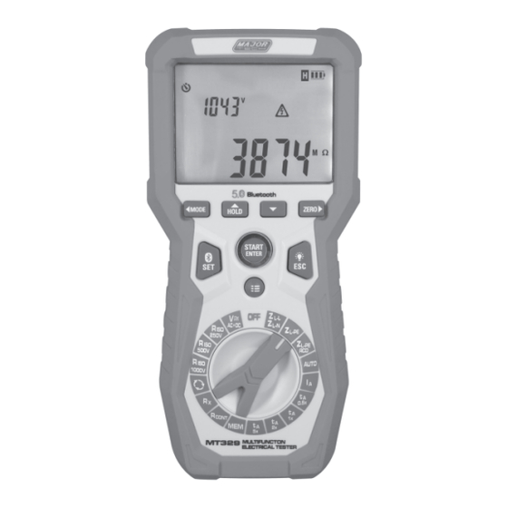
- Page 1 INSTRUCTION MANUAL MT329 HANDHELD MULTIFUNCTIONAL INSTALLATION TESTER...
-
Page 3: Table Of Contents
Contents Page no 1. Safety ..................... 5 International Safety Symbols............5 Safety Notes................5 1.3. Warnings..................5 1.4. Cautions...................5 2. Description ..................2.1. Meter Description..............6 2.2. Display Icons Description............7 2.3. Button Description..............8 2.4. Selector Switch Description............9 3 Measurements................3.1. Voltage and Frequency Measurement........10 3.2. - Page 4 Contents Page no 5.8. Measurement of RCD Parameters ..........26 5.8.1. RCD Tripping Test and t Tripping Time Measurement ..... (For t Measurement Function) ........5.8.2. RMS Leakage Current During RCD Tripping Time ....Measurement..............27 5.8.3. RE - Protective Conductor Resistance for RCD.....27 5.8.4.
-
Page 5: Safety
1. SAFETY 1.1. International Safety Symbols This symbol, when adjacent to another symbol or terminal, indicates that the user must refer to this manual for further information. This symbol, when adjacent to a terminal, indicates that hazardous voltages may be present under normal use. Double insulation. -
Page 6: Description
4 - Down Button 5 - ZERO/Right Button 6 - Setup/Bluetooth Button 7 - START/ENTER Button 8 - ESC/Backlight Button Bluetooth 9 - Memory/Lock Button 10 - Rotary Selector Switch 11 - Input Terminals 12 - Battery Cover MULTIFUNCTION MT329 ELECTRICAL TESTER... -
Page 7: Display Icons Description
2.2. Display Icons Description Ready to Test High Noise in Measurement Set Up Test Button Locked Auto Range Mode WARNING! Test Leads Zeroed Dangerous Voltage AC+DC Mode RCD Current Multiplication Factor Data Hold RCD Touch Voltage Setting Battery Level Indicator Current Waveform Auto Power-Off RCD Type... -
Page 8: Button Description
2.3. Button Description Mode: Switches between different measurement modes. Voltage mode only. Left: Toggles display results or adjusts setting options. HOLD: Keeps the measurement on the display as it was at the time the button is pressed. Up: Adjusts setting options. Down: Adjusts setting options. -
Page 9: Selector Switch Description
2.4. Selector Switch Description Voltage: Measures AC or DC voltage between two points in a circuit. Insulation Resistance: Measures the resistance of insulation materials using selectable test voltages Phase Sequence Test: Checks the correct sequence of a three- phase power supply. Low-Current Resistance: Measures resistance with a minimal test current of 200μA. -
Page 10: Measurements
3. MEASUREMENTS WARNING: During measurements (Fault loop impedance, RCD), avoid touching earthed and accessible parts in the tested electrical installation to prevent shock. During measurements, do not switch the selector switch as this may damage the meter and pose a hazard to the user. Press and hold the Setup/Bluetooth Button while switching on the meter to enter the setup menu. -
Page 11: Insulation Resistance Measurement
3.2. Insulation Resistance Measurement 1. Set the Selector Switch: Turn the knob switch to the R 250V, 500V or R 1000V position. 2. Connect the Test Leads: Connect the test leads as shown in the figure below. 3. Initiate Measurement: Press and hold the START/ENTER button to begin the measurement. -
Page 12: Phase Sequence Test
5. View Results: Check the LCD display for the phase sequence results. The possible results are as follows: 6. Press the START/ENTER Button to start a new measurement. Note: For this test, ensure that the input AC voltage is within the range of 100 to 550V and the frequency is between 45 and 65Hz. -
Page 13: Low-Current Resistance Measurement
3.4. Low-Current Resistance Measurement 1. Set the selector switch to the Rx Position. 2. Connect the meter as shown in the figure below. 3. The tester will immediately and continuously test while this function is selected, you can view the test results. Press the ZERO Button to compensate for current resistance (zeroing the test leads). -
Page 14: Measurements Of Fault Loop Parameters
3.6. Measurements of Fault Loop Parameters WARNING: If the mains under test includes residual current devices (RCDs), they should be bypassed during measurement. Note that bypassing may alter the circuit, causing results to differ slightly from actual values. After completing the measurement, restore the mains to its original state and verify the operation of the residual current device. -
Page 15: Measurement Of Fault Loop Parameters In L-N, L-L And............ L-Pe Systems
4. If the LCD is displaying “ZERO”, press the ZERO Button again to cancel the zeroing of the test lead resistance. 3.6.2. Measurement of Fault Loop Parameters in L-N, L-L, and L-PE Systems • RCDs present in the circuit may trip during measurement. •... - Page 16 3. The LCD displaying “READY” indicates that the instrument is set up and ready for measurement. 4. Press the START/ENTER Button to begin the measurement. Read the measurement results and press the MODE or ZERO Button to view other results. Power supply Short circuit voltage U...
-
Page 17: Measurement Of Fault Loop Impedance In An L-Pe Systems
3.6.3. Measurement of Fault Loop Impedance in L-PE Systems Protected by an RCD • This feature measures fault loop impedance without altering the power supply, provided the residual current device (RCD) is rated at a minimum of 30mA. • If the L and N terminals are reversed, the tester will automatically adjust and continue the test. - Page 18 Type A/AC RCD Type A/AC/B RCD 5. Press the START/ENTER Button to begin the measurement. 6. Read the measurement results and press the MODE or ZERO Button to view other results. Notes: • If only the measurement of U , R is selected, these values are measured with a 0,41l n...
-
Page 19: Measurement Of Rcd Tripping Time
Additional Display Information Meter is set up and ready for measurement. Voltage between the L and PE terminals is out of measurement range. Safe touch voltage has been exceeded. Indicates a measurement error due to a loss of voltage after the measurement. RCD did not trip or the RCD tripped while measuring U and/or R . - Page 20 Type A/AC/RCD Type A/AC/B RCD 5. Press the START/ENTER Button to begin the measurement. 6. Read the measurement results and press the MODE or ZERO Button to view other results. Touch Voltage U Tripping Time l n Notes and information displayed by the meter are the same as in section 3.7.1.
-
Page 21: Automatic Measurement Of Rcd Parameters
3.7.3. Automatic Measurement of RCD Parameters • The instrument automatically measures the RCD tripping time t , tripping current I , touch voltage U and earth resistance R • In this mode, you only need to initiate the measurement and reset the RCD each time it trips;... -
Page 22: Storing Measurement Results
Additional Information RCD is in good working order. RCD is defective. RCD needs to be reset. 4. STORING MEASUREMENT RESULTS • The instrument can store up to 1000 sets of measurements, organized into multiple groups. • The entire memory is divided into 10 memory Banks, each with 99 memory Cells. -
Page 23: Accessing Stored Measurements
4.2. Accessing Stored Measurements 1. Switch on the meter. Set the Selector switch to the MEM Position. 2. Press the ESC Button to select the Bank or Cell, press the HOLD Buttons to adjust the Bank or Cell, and press the MODE or ZERO Buttons to view the stored measurement data. -
Page 24: Specifications
5. SPECIFICATIONS 5.1. Voltage Measurement Range Resolution Basic Uncertainty 0.0V~550.0V 0.1V ±(2.0% + 3 digits) Frequency Range: 45 to 65Hz 5.2. Phase Sequence Test • Test Voltage Range: 100V to 550V AC. • Test Frequency Range: 45Hz to 65Hz 5.3. Insulation Resistance Terminal Range Resolution Accuracy... -
Page 25: Continuity Measurement Of Protective Earth Conductors And............ Equipotential Bonding (±200Ma Current)
5.5. Continuity Measurement of Protective Earth Conductors and Equipotential Bonding (±200mA current) Range Resolution Basic Uncertainty 0.00 to 19.99Ω 0.01Ω 20.0 to 199.9Ω 0.1Ω ±(2.0% + 3 digits) 200 to 400Ω 1Ω • Voltage on Open Terminals: 4…9V • Output Current at R<2Ω: min 200mA (ISC: 200...250mA) •... -
Page 26: Z L-Pe Fault Loop Impedance Measurement With Rcd
5.7. Z Fault Loop Impedance Measurement with RCD L-PE (Without Tripping the RCD) 5.7.1. Z Fault Loop Impedance Measurement Range Resolution Basic Uncertainty 0.0 to 19.99Ω 0.01Ω ±(6.0% + 10 digits) 20.0 to 199.9Ω 0.1Ω ±(6.0% + 5 digits) 200 to 1999Ω 1Ω... -
Page 27: Rcd Tripping Test And T Tripping Time Measurement
5.8.1. RCD Tripping Test and t Tripping Time Measurement (For t Measurement Function) RCD Type Multiplication Measurement Resolution Basic Factor Setting Range Uncertainty 10 to 300ms 1 l n General 10 to 300ms 2 l n 10 to 150ms 5 l n 10 to 40ms 0.1ms ±(2% + 10 digits) -
Page 28: Rcd L A Trip Current Measurement For Sinusoidal Residual
5.8.4. Measurement of Touch Voltage U referred to Rated Residual Current Measurement Resolution Test Basic Range Current Uncertainty 0 to 9.9V 0.1V 0.4 X l n 0 to 10% ± 5 digits 10.0 to 99.9V 0 to 15% 5.8.5. RCD l Tripping Current Measurement for Sinusoidal Residual Current Selected RCD Measurement Resolution Test Step... -
Page 29: Current
5.8.7. RCD l Trip Current Measurement for Smooth DC Residual Current Selected RCD Measurement Resolution Test Step Basic Rated Current Range Current Size Uncertainty 10mA 2.0 to 21.0mA 0.1mA 0.20x 30mA 6.0 to 63.0mA 5% of ±10% l n l n to 2.1x 100mA 20 to 210mA... -
Page 30: App Download
(for Android) or scan the QR code to download the APP. 8. PRODUCT REGISTRATION Register your new Major Tech product today to activate your warranty and stay up-to-date with the latest software and firmware updates, ensuring optimal performance and security. By registering, you'll also gain access to exclusive offers and trade-in opportunities, helping you get the most value from your purchase. - Page 31 Ÿ Normal wear and tear of mechanical components Ÿ Failures caused by use outside the product's specifications Ÿ Any product which, in the opinion of Major Tech, has been misused, contaminated, or damaged due to neglect. Check Procedure Prior to contacting Major Tech or a distributor regarding a warranty claim, please check the following: Ÿ...
- Page 32 MAJOR TECH (PTY) LTD South Africa Australia www.major-tech.com www.majortech.com.au sales@major-tech.com info@majortech.com.au...
Need help?
Do you have a question about the MT329 and is the answer not in the manual?
Questions and answers