
Subscribe to Our Youtube Channel
Related Manuals for OKM ROVER C4


Summary of Contents for OKM ROVER C4
- Page 1 INTRODUCTION TECHNICAL SPECIFICATIONS CONTROL ELEMENTS ASSEMBLY & PREPARATION OPERATING MODES OKM ROVER C4 MANUAL DATA TRANSFER...
- Page 2 This documentation is available "as presented" and without any kind of warranty. In no circumstances OKM takes responsibility for lost profits, usage or data losts, interruption of business activities or all kind of other indirectly damages, which developed because of errors in this documentation.
-
Page 3: Table Of Contents
TABLE OF CONTENTS 5 OPERATING MODES ..............16 5.1 3D GROUND SCAN ..................16 1 INTRODUCTION ................4 5.1.1 Preparing a 3D Ground Scan ..............16 1.1 PREFACE ......................4 5.1.1.1 Saving into Memory .................18 1.2 IMPORTANT NOTES ..................5 5.1.1.2 Transferring to Computer................19 1.2.1 General Notes ..................... -
Page 4: Introduction
Please take your time to read this User Manual and familiarize yourself with the operation, func- tionality and how to utilize the Rover C4. We also offer training for OKM equipment in our fac- tory and on-site. We strive to maintain a worldwide dealer network for assistance and support. -
Page 5: Important Notes
• the power supply of the device or the batteries are too low, Being an electronic device, the Rover C4 has to be treated with caution and treated with care • the cables are too long, as with any electronic device. -
Page 6: Danger Of Explosion During Excavation
• When shipping, use the original factory carton or similar heavy-duty container and provide The Rover C4 is a sturdy instrument, but it is not designed to withstand abuse. In caring for your sufficient padding around all parts. ground scanner, there are several important DOs and DON‘Ts to remember: •... -
Page 7: Technical Specifications
2 TECHNICAL SPECIFICATIONS The technical specifications are medial values. During operation slight variations are possible. 2.1 CONTROL UNIT Dimensions (L x W x H) 360 x 320 x 140 mm Weight 1.6 kg Input (max) 19 V DC, 3.16 A, 60 W Processor / Main CPU Cortex M3, 32 MHz Processor / Slave CPU... -
Page 8: Control Elements
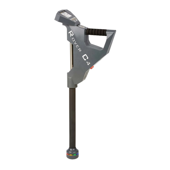
3 CONTROL ELEMENTS In this section you learn more about the fundamental use of all control elements for this measuring instrument. All connections, inputs and outputs are explained in detail. Assembled Metal Detector with Standard Probe Control Panel with Touchscreen Control CONTROL ELEMENTS Unit... -
Page 9: Control Unit
3.1 CONTROL UNIT Touchscreen Buttons Handle LED Lighting Speakers Charging Sensor Charger Button Description Socket Socket This button has 2 different meanings: Charger Socket / Charging LED: When the internal battery is too low, you have to recharge it by 1) Power your detector on and off. - Page 10 Back Bluetooth Battery Information icon indicates if Bluetooth headphones have been successfully connected with the Rover C4. More information on how to connect Bluetooth headphones is available in section „5.6.2 Head- phones“ on page Battery: The battery icon indicates the current charge state of the internal battery. If the battery is too low ( ), you have to recharge it by using the appropriate charger.
-
Page 11: Standard Probe / Super Sensor
Both measuring probes are equipped with a light sphere called LED Orbit, that can indicate the The Rover C4 can be operated with any Bluetooth headphones available on the market. Your measured values by color changes during the scanning process. -
Page 12: Assembly And Preparation
4 ASSEMBLY AND PREPARATION 4.1 PAIRING BLUETOOTH Prior to transferring scan data to the Visualizer 3D Studio software, the Bluetooth of your com- puter must be paired with your OKM detector. ASSEMBLY & PREPARATION 12 / 36... - Page 13 In the "Add a device" dialog select Bluetooth. Make sure your device is turned on and discoverable. Confirm your selection with click on Done. Click on OKM Rover C4. 13 / 36...
-
Page 14: Assembling The Detector
4.2 ASSEMBLING THE DETECTOR Please follow the following instruction to assemble your detector and get ready for your first measurement. Make sure to recharge the internal bat- Alternatively, you can use the Power Pack Either connect the Standard Probe or the Super Sensor to the Sensor Socket. tery of the detector before going into the to recharge the detector. - Page 15 OPERATING MODES 15 / 36...
-
Page 16: Operating Modes
5.1 3D GROUND SCAN The operating mode "3D Ground Scan" provides a graphical measurement of any area for anal- After powering on the Rover C4 metal detector by pushing the button, a splash screen ap- ysis on a computer. For the measurement you can either use the Standard Probe or the Super pears on screen while the system is booting up: Sensor. - Page 17 First, set the number of measure points (Im- The impulse mode sets the way of how the sin- Selecting the scan mode tells the Rover C4 Define the type of data transfer. The transfer pulses), which will be recorded for each sin- gle impulses (measure values) will be released how you will step out the scan field.
-
Page 18: Saving Into Memory
5.1.1.1 Saving into Memory If you have selected "Memory" as transfer mode, you need to select one of the four mem- ory areas. Select one of the four memory areas in which In case you selected a memory area that al- Now you can get ready and start your first the new scan data should be stored. -
Page 19: Transferring To Computer
If you selected "Computer" as transfer mode, you need to establish a wireless data con- nection to the Visualizer 3D Studio software on your PC. Rover C4 is now waiting for an incoming Blue- Set up your Visualizer 3D Studio software with... -
Page 20: Conducting A 3D Ground Scan
5.1.2 Conducting a 3D Ground Scan a) If you have selected the impulse mode "Automatic" just keep going slowly until you have After all parameters have been adjusted, the device is ready to start the first scan line. Begin- reached the end of the first scan line. When you already have defined the number of im- ning from this moment, the display will indicate the current number of scan lines and the current pulses then the device will stop automatically at the end of the line, otherwise –... -
Page 21: Pinpointer
In this operating mode all measured data will be sent directly to a computer. Therefore, a wireless data connection to the Visualizer 3D Studio software must be established first. Rover C4 is now waiting for an incoming Blue- Set up your Visualizer 3D Studio software with... -
Page 22: Conducting A Pinpointer Scan
5.2.2 Conducting a Pinpointer Scan After the data transfer to the computer has been established, you are ready to start your mea- surement. Hold the Super Sensor correctly during the measurement. The display shows the active Pinpointer After canceling the Pinpointer mode, the de- screen. -
Page 23: Analyzing A Pinpointer Scan
5.2.3 Analyzing a Pinpointer Scan While scanning in Pinpointer mode you might see one or more different signatures, from which you can recognize a specific characteristic of any target. Non-ferromagnetic metals Ferromagnetic metals Non-ferrous targets have a pure Ferromagnetic targets have a positive signature. -
Page 24: Magnetometer
5.3 MAGNETOMETER The operating mode "Magnetometer" allows to research the area in regard to ferromagnetic metals, e.g. iron, cobalt and nickel and other metals or objects which include traces of such metals. Primarily, this function is an acoustic mode, it generates a very rough graphical repre- sentation on the display to visualize the highs and lows. -
Page 25: Conducting A Magnetometer Scan
5.3.2 Conducting a Magnetometer Scan You should use the operating mode "Magnetometer" to remove such disturbing metal pieces from the area that you like to scan. The less metals near to the surface, the better your result in Right after activating the “Magnetometer” mode, no sound should come from the device. If you the operating mode "3D Ground Scan". -
Page 26: Mineral Scan
5.4 MINERAL SCAN When prospecting for mineral deposits or naturally occurring minerals or formations located in the ground, it is important to work in a clean environment, free of debris. Debris may contami- nate the area and lower the probability of success. The presence of debris may also lead to false or misleading signals. - Page 27 Select one of the memory areas by using In case you selected a memory area that al- If you have selected a free memory area or button. Confirm the selection with ready contains data from a previous scan, an confirmed to overwrite an occupied one, the information dialog appears.
-
Page 28: Conducting A Mineral Scan
5.4.2 Conducting a Mineral Scan 5.4.3 Analyzing a Mineral Scan If the Mineral Scan screen is shown on the display of the Rover C4, position yourself at the After transferring the scan data to start point (A) of your measurement and press the button. -
Page 29: Memory To Pc
The Rover C4 is equipped with four memory areas that can be used to store either 3D Ground one to watch for within the scans. As Scans or Mineral Scans. After each data transfer you can decide to clear the used memory area. - Page 30 Now the device waits for a Bluetooth connec- Set up your Visualizer 3D Studio software with Power on the device and select the operating Select one of the four memory slots to trans- tion initiated by the software. all the corresponding settings as explained in mode "Memory To PC"...
- Page 31 The device starts to transfer all data from the After transferring the measure values you If you decided to clear the memory area, it will selected memory area. Simultaneously you can decide if you would like to keep the data be displayed as empty in the memory screen should see the incoming measure values in in the internal memory of the device.
-
Page 32: Settings
5.6 SETTINGS 5.6.3 Language The Rover C4 can be used in different languages to simplify the handling. Use the button to loop 5.6.1 Volume through all languages. Confirm your preferred language with the button or the button. This option changes the volume of the internal speakers or the connected Bluetooth headphones. -
Page 33: Brightness
In dark These information may be useful if you are contacting your local OKM distributor for additional environments you can turn the brightness down. -
Page 34: Preparing Data Transfer
File > Import from the appears in the list. Now select the entry and menu or you simply click the icon. click Next. Select “Rover C4 (version 3.4 or higher)” from the list and click Next. DATA TRANSFER 34 / 36... - Page 35 3D Ground Scan Select the operating mode and click Next. Enter the Field Length and select the Scan Enter title and scan field dimensions. You may Select the corresponding soil type. Mode, then click Next. also apply GPS coordinates and add notes and Start the scan data import by clicking OK.
- Page 36 OKM GERMAN DETECTORS Based in Altenburg, Germany, we are developing and manufacturing geophysical detectors since 1998. Our unique detection technology helps to visualize buried objects and structures. OKM GmbH Julius-Zinkeisen-Str. 7 | 04600 Altenburg | Germany +49 3447 499300 0 +49 162 419 2147 info@okmdetectors.com...
Need help?
Do you have a question about the ROVER C4 and is the answer not in the manual?
Questions and answers