OKM eXp 6000 Manual
Hide thumbs
Also See for eXp 6000:
- User manual (86 pages) ,
- Quick start manual (6 pages) ,
- Quick start manual (4 pages)

Related Manuals for OKM eXp 6000


Summary of Contents for OKM eXp 6000
- Page 1 INTRODUCTION TECHNICAL SPECIFICATIONS CONTROL ELEMENTS ASSEMBLY & PREPARATION OPERATING MODES OKM eXp 6000 MANUAL SCANNING TECHNIQUES...
- Page 2 Any information contained in these operating instructions may be changed without prior notice. OKM does not make any warranty for this document. This also applies without limitation to implied assurances of merchantability and fitness for a specific purpose. OKM does not assume any re- sponsability for errors in this manual or for any incidental or consequential damage or loss associated with the delivery, exploitation or usage of this material.
-
Page 3: Table Of Contents
2.7 GPS RECEIVER ......................9 5.8.2 Language ........................41 3 CONTROL ELEMENTS ..................10 5.8.3 Date ........................42 3.1 EXP 6000 COMPONENTS ..................10 5.8.4 Time ........................42 3.2 MEASURING PROBES AND SENSORS ..............11 5.8.5 Layout ........................42 3.3 TELESCOPIC ROD .....................12 5.8.6 Factory Reset ...................... -
Page 4: Introduction
Please take your time to read this User Manual and familiarize yourself with the operation, functionality and how to utilize the eXp 6000. We also offer training for your equipment in our factory. We strive to maintain worldwide dealer network for assistance and support. Please visit our website for more information. -
Page 5: Important Notes
• the unit is operating to close to devices which sends out disturbances or Being an electronic device, the eXp 6000 has to be treated with caution and treated with care • atmospheric conditions (electrical storms, lightning, etc.). -
Page 6: Maintenance And Services
Prior to using your eXp 6000 please be sure that all batteries and accumulators are fully charged. of them to break and be triggered. Even seemingly harmless objects such as cartridges or large ammunition are anything but that. -
Page 7: Care And Use
1.5 CARE AND USE 1.6 PROTECTING YOUR INVESTMENT The eXp 6000 and its components like the probes and sensors are sturdy equipment, but are not Often detector users become disappointed when their new detector becomes less and less designed to withstand abuse. In caring for your professional ground scanner, there are several responsive and seems to have lost some of its original peak performance. -
Page 8: Technical Specifications
TECHNICAL SPECIFICATIONS 8 / 49... -
Page 9: Super Sensor
2 TECHNICAL SPECIFICATIONS 2.3 SUPER SENSOR Length 950 mm 2.1 CONTROL UNIT Weight approx. 1.0 kg Dimensions (H x W x D) 120 x 210 x 280 mm Receiver Dual / Hi-Gain – Vertical Weight approx. 2.34 kg Geophysical Phase Reader – EMSR Voltage 11.8 - 19 V DC, 50 W maximal Sensor technology... -
Page 10: Control Elements
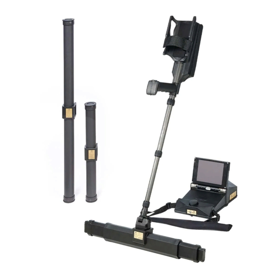
3 CONTROL ELEMENTS In this section you learn more about the fundamental use of all control elements for this mea- suring instrument. All connections, inputs and outputs are explained in detail. 3.1 EXP 6000 COMPONENTS Video Glasses Headphones Carrying Strap... -
Page 11: Measuring Probes And Sensors
3.2 MEASURING PROBES AND SENSORS Each measuring probe that you attach to the Telescopic Rod is optimized for its very special task. Telescopic Rod The eXp 6000 supports the following probes: • Telescopic Probe This horizontal probe is perfectly used to scan wide areas in short time. You can extend its Probe Mount length between 82 and 124 cm. -
Page 12: Telescopic Rod
3.3 TELESCOPIC ROD The Trigger Button with LED is used to switch on and off the Telescopic Rod. Additionally, you start a new measurement, run the next scan line and stop the first scan line in automatic mode. The LED ring can indicate following states: Trigger Button Green: •... -
Page 13: Control Unit
3.4 CONTROL UNIT The Control Unit is the processing center of the eXp 6000. Via Control Unit, various functions and operating modes can be selected, all measured values can be recorded and stored. Display with Touchscreen Air Ventilation Speaker Multi-function... -
Page 14: Assembly And Preparation
• Control Unit This is the main controller of the eXp 6000 where you select your operating modes and view your current measurement data. Furthermore all your scans will be saved in its internal memory before transferring it to a computer for detailed analyses. - Page 15 To unfold the display of the eXp 6000 Control Pull the display out completely. Turn the display into an appropriate angle ... according to your personal preferences. Unit follow the following steps. Push the Multi-function Control Knob at After a short moment the boot up screen will...
-
Page 16: Telescopic Rod
4.2 TELESCOPIC ROD 4.2.1 Connecting Probes It is recommended to charge the internal batteries of the Telescopic Rod before conducting any Depending on the task you want to fulfill, you have to attach one of your measuring probes to the measurement. -
Page 17: Adjusting The Length
4.2.2 Adjusting the Length For your personal comfort you should extend the Telescopic Rod to your preferred length. Additionally you may use the arm strap to fix the arm rest to your arm. Thus working with the Arm Strap with Telescopic Rod is more comfortable. -
Page 18: Mounting The Gps Receiver
Control Unit and Telescopic Rod. To do so, please plug the chargers into the designated Charger Sockets. It is also possible to attach the optional OKM Power Pack. This is a good option to recharge the batteries outdoors. -
Page 19: Connecting Wireless Headphones
The eXp 6000 can be operated with any Bluetooth headphones available on the market. Your eXp You may also pair any Android device with your eXp 6000 Control Unit to stream the display in- 6000 comes with pre-paired Bluetooth headphones. - Page 20 After a short moment the application connects to the Control Unit and you will see the screen output of the eXp 6000 also on your Android device screen. If you are using an Android Tablet PC with touchscreen itself, you can use this as a replacement of the eXp 6000 display.
- Page 21 OPERATING MODES 21 / 49...
-
Page 22: Operating Modes
Settings Information Change the language, date, time, volume, screen layout and other settings. The home screen provides detailed information about the current status of your eXp 6000: • Information Display details on your eXp 6000 such as status as well as serial numbers. -
Page 23: Ground Scan
5.1 3D GROUND SCAN This operating mode allows you to do a measurement with a graphical representation where- The 3D Ground Scan mode is your primary function. This is the mode where you are going to find by all measured values will be stored in the internal memory of the device. Also you have the the targets and locate areas of disturbed soils. - Page 24 Zigzag mode measurements start During the first line the device will read val- In Automatic Mode, the eXp 6000 will take • at the end of the line which was scanned be- Alternatively, you can also use the Trigger ues continuously without stopping.
- Page 25 Repeat this procedure until you scanned your ferrous items and blue for cavities, water re- serves and earth interferences. field completely. Step by step a graphical representation will appear on the screen of the eXp 6000. 25 / 49...
-
Page 26: Pinpointer
The Super Sensor cannot swing, it must remain in the vertical orientation. Please try to capture area. These values can also be changed The eXp 6000 will assist you in that task with the complete object, which means you should measure beyond the edges of the object. Repeat later on in the Visualizer 3D Studio soft- its integrated Orientation Sensor. - Page 27 Ferromagnetic metals Non-ferromagnetic metals Ferromagnetic targets have a Non-ferrous targets have a pure positive-negative-signature. positive signature. In a signature of a non-ferrous target you can recognize that there is only a positive amplitude The typical signature of a ferromagnetic metal like iron includes a positive (red) and a negative (blue) amplitude.
-
Page 28: Mineral Scan
The Visualizer 3D Studio software will identify patches of mineralization. When conducting scans with the OKM eXp 6000, it is presumed that the user or operator is familiar with the prop- The following procedures do not apply to those who are looking for buried treasures er operating technique. - Page 29 Start the eXp 6000 and select “Mineral Scan” Go to your starting position and start the Make sure that your Super Sensor remains You may pause and continue your scan as you from the main menu. measurement by pressing the Trigger Button...
-
Page 30: Analyzing A Mineral Scan
Afterwards you will be able to open and view the scan via the eXp 6000 File Explorer (see „5.7 File Explorer“ on page 36). Though you will be able to view the scan on the eXp 6000 display, it is recommended to complete the analysis on the PC. - Page 31 5.3.3 Determining the Position of Anomalies After an anomaly has been found it is very important to know how to find the location. This is Practical experience and the repea- done very simply by entering in the field length into the Characteristics (F9 key) in the Visualizer tability factor from several locations 3D Studio software.
-
Page 32: Live Scan
5.4 LIVE SCAN To work in the operating mode Live Scan connect the Live-Stream Sensor to your eXp 6000. In this operating mode you do not have to keep a defined scan direction. You can walk forwards or backwards over your measured area. On the screen you will see immediately what is currently situated right under the measuring probe. -
Page 33: Magnetometer
5.5 MAGNETOMETER By selecting the Magnetometer operating mode from the main menu, you can scan the sub-sur- face for ferromagnetic targets and areas of the soil with a low iron content. Also, you may view the oscilloscope output on the monitor to be able to identify ferromagnetic materials in the ground. -
Page 34: Tunnel Scan
Trigger Button because the Refer to section „6.3 Manual or Automatic“ on Since the Tunnel Sensor is shorter than the eXp 6000 will record scan data immediately. page 48 for further explanations concern- Super Sensor, the antenna has to be held ing the impulse mode setting. - Page 35 Preparation: A tunnel signal in the Visualizer 3D Studio software is typically represented by a depression from Create a path and be sure that it is clear of obstacles. the top of the scan. The software will show in many cases the curvature or the top of the tunnel, The path must be straight.
-
Page 36: File Explorer
Copy to USB Flash Drive Use this button to copy all selected files to an external USB flash drive. Delete Selected Files Use this button to delete all selected files permanently from the eXp 6000 Control Unit. File Counter Jump to Sidebar... -
Page 37: File List Item
The following probe indications are possible: Delete File Telescopic Probe Select this action to delete the file permanently from the hard disk of the eXp 6000. Start GPS Navigation Super Sensor Navigate to the scan area where the selected file has been performed. This action is only available when the selected scan has been performed with GPS enabled. -
Page 38: Open Files And View Scan Images
The Position indicates the GPS coordinates of your current position, while the Target is the place where you have performed your scan. There are two possible ways to delete files from your eXp 6000: The Distance tells you how far you have to go to reach your target GPS position. - Page 39 Examples of how to correct your walking direction to find your target: You are walking north but should go to the You are walking west but should go to the You are walking south which is exactly the Northeast. East. So you are walking in the opposite di- right way to your scan area because the di- rection.
-
Page 40: Copying Files To Usb Flash Drive
If you want to analyze your recorded scan images with the Visualizer 3D Studio software you The eXp 6000 offers many settings which can be configured. After selecting the settings icon must copy your files to an USB flash drive first. -
Page 41: General
Telescopic Rod as described in section „4.2.3 Mounting the GPS Receiver“ on page If this option is enabled you can control your eXp 6000 Control Unit by using an external An- droid device. If the box is checked, GPS is enabled and GPS coordinates will be recorded. In that way you will be able to navigate to your scan field later on as described in section „5.7.5 GPS... -
Page 42: Language
5.8.2 Language 5.8.3 Date The eXp 6000 Control Unit comes with a variety of different languages to make it as easy as Select one of the available date formats and adjust the day, month and year options to your local possible to operate the device and its functions. -
Page 43: Layout
Anytime during the operation of the eXp 6000 you may click on the layout icon in the top status- bar to change the current theme immediately. If you select the option "Use automatic layout”, the eXp 6000 Control Unit selects the current layout automatically by measuring the light condition of the environment. -
Page 44: Factory Reset
5.11 SOFTWARE UPDATE The eXp 6000 is able to update its software after changed or improved by OKM. For that you need to download a specific update file from the OKM website. As soon as a new update is available OKM is publishing the file on the website. - Page 45 SCANNING TECHNIQUES 45 / 49...
-
Page 46: Scanning Techniques
6 SCANNING TECHNIQUES The eXp 6000 will give you an indication of the probe's vertical or horizontal orientation at all times during a scan. Find this symbol in the left bottom corner: 6.1 PROBE ORIENTATION During a measurement the probe should always have the same distance to the ground. General- ly we recommend a height of about 5 to 10 cm (2 to 6") from the surface of the ground if possible. -
Page 47: Orientation Of Super Sensor / Tunnel Sensor
6.1.1 Orientation of Super Sensor / Tunnel Sensor 6.1.2 Orientation of Telescopic Probe / Live-Stream Sensor The following table explains the symbols of all vertical probes. The following table explains the symbols of all horizontal probes. High High Correction Correction inclination inclination inclination... -
Page 48: Parallel Or Zigzag
To use the Super Sensor with eXp 6000, simply connect it to the Telescopic Rod and always hold the antenna vertical to the ground. Make sure the Super Sensor is oriented correctly. - Page 49 OKM GERMAN DETECTORS Based in Altenburg, Germany, we are developing and manufacturing geophysical detectors since 1998. Our unique detection technology helps to visualize buried objects and structures. OKM GmbH Julius-Zinkeisen-Str. 7 | 04600 Altenburg | Germany +49 3447 499300 0 +49 162 419 2147 info@okmdetectors.com...
Need help?
Do you have a question about the eXp 6000 and is the answer not in the manual?
Questions and answers