Table of Contents
Advertisement
Advertisement
Table of Contents

Related Manuals for OKM eXp 4000


Summary of Contents for OKM eXp 4000
- Page 1 FS Future Series eXp 4000 Version 2.1 User's Manual...
- Page 2 Any information contained in these operating instructions may be changed without prior notice. OKM does not make any warranty for this document. This also applies without limitation to implied assurances of merchantability and fitness for a specific purpose. OKM does not assume any responsability for errors in this manual or for any incidental or consequential damage or loss associated with the delivery, exploitation or usage of this material.
-
Page 3: Table Of Contents
6.1.1 Front View ..........................6.1.2 Rear View ..........................7 Operating Modes ..........................7.1 Magnetometer ..........................7.2 Ground Scan ..........................7.2.1 New Scan ..........................7.2.2 Browse Scans ........................7.3 Metal Detector ..........................7.4 Discrimination ..........................7.5 Empty Memory ..........................OKM Ortungstechnik GmbH www.okmmetaldetectors.com... - Page 4 8.2.4 Tips from the trainers themselves ..................9 Optional Equipment ..........................9.1 Super Sensor ..........................9.1.1 Usage ........................... 9.2 DDV system ..........................9.2.1 Calibration ........................... 9.2.2 Adjust the discriminator ....................... 9.2.3 Ground Balance ........................10 Error Messages ..........................OKM Ortungstechnik GmbH www.okmmetaldetectors.com...
- Page 5 Illustration 6.1: Control unit with power supply and probe ..............42 Illustration 6.2: Control unit, front view ....................43 Illustration 6.3: Control unit, rear view ....................44 Illustration 7.1: Magnetometer: Main Menu, Representation of Values ..........47 Illustration 7.2: Ground Scan ........................48 OKM Ortungstechnik GmbH www.okmmetaldetectors.com...
- Page 6 Illustration 10.3: Internal Hardware Error ..................... 72 Illustration 10.4: The external power supply has to be charged ............. 73 Illustration 10.5: Shutting down the system ................... 73 Illustration 10.6: Shutting down the system is not possible ..............73 OKM Ortungstechnik GmbH www.okmmetaldetectors.com...
-
Page 7: Introduction
1 Introduction HAPTER Introduction... -
Page 8: Preface
Please take your time to read this User Manual and familiarize yourself with the operation, functionality and how to utilize the eXp 4000. We also offer training for your equipment in our factory and on-site. We strive to maintain worldwide dealer network for assistance and support. Please visit our web site for more information. -
Page 9: Important Notes
Please read the user manual of the software! 1.2.1 General Notes Being an electronic device, the eXp 4000 has to be treated with caution and treated with care as with any electronic device. Any failure to observe the safety precautions given or any use for purposes other than the ones it is designed for may result in damage or destruction of the processing unit and/or its accessories or connected components. -
Page 10: Data Safety
Prior to using your eXp 4000 please be sure that all batteries and accumulators are fully charged. Also allow the batteries to completely discharge before recharging them, regardless if you are working with the external battery or with internal accumulators. - Page 11 Moving such an object may cause those crystals to produce friction, leading to an explosion. If you come across such relics, mark the place and do not fail to report the find to the police. Such objects always pose a danger to the life of hikers, walkers, farmers, children and animals. OKM Ortungstechnik GmbH www.okmmetaldetectors.com...
-
Page 13: Install/Uninstall Usb Drivers On Windows
2 Install/Uninstall USB drivers on Windows HAPTER Install/Uninstall USB drivers on Windows In this chapter you will learn how to install the USB drivers, that are necessary to transfer data from the machine to your computer software. Please make sure to read the proper section appropriate to your Windows operating system. -
Page 14: Windows Xp
Illustration 2.2: Install USB drivers: Windows XP, Step 2 In other versions of Windows this window should not appear. In the following dialog window like figure 2.3 select the entry "Install software from a list …" and click Next. OKM Ortungstechnik GmbH www.okmmetaldetectors.com... -
Page 15: Illustration 2.3: Install Usb Drivers: Windows Xp, Step 3
Data carrier..Immediately another window appears where you click on the button Search ... Then select the file OKM_LE.INF , which you can find in the directory \drivers\usb_cable of your software CD. Afterwards you have to click on Open, OK and Next, to start the installation of the files. OKM Ortungstechnik GmbH www.okmmetaldetectors.com... -
Page 16: Illustration 2.5: Install Usb Drivers: Windows Xp, Step 5
After successful installation of the driver a message like in figure 2.6 will appear on your computer screen. Now the drivers of your device are installed and you can transfer data to your PC. Illustration 2.6: Install USB drivers: Windows XP, Step 6 OKM Ortungstechnik GmbH www.okmmetaldetectors.com... -
Page 17: Uninstall Usb Drivers On Windows Xp
After that a dialog like in figure 2.8 appears. There you can find the entry system and click twice on it. Illustration 2.8: Uninstall USB drivers: Windows XP, Step 2 The dialog from figure 2.9 appears on your screen. Click on the tab hardware and after that the button device manager. OKM Ortungstechnik GmbH www.okmmetaldetectors.com... -
Page 18: Illustration 2.9: Uninstall Usb Drivers: Windows Xp, Step 3
USB devices will be shown. Illustration 2.10: Uninstall USB drivers: Windows XP, Step 4 Mark the device which you like to delete, which means "eXp 4000. Additionally the device may be listed as “OKM Quick Link”. Then click on the button. -
Page 19: Illustration 2.11: Uninstall Usb Drivers: Windows Xp, Step 5
Windows XP, Step 5 The dialog from figure 2.11 appears. Click there on the button OK. Now all drivers will be deleted from your computer. If needed you can now install the USB driver again correctly. OKM Ortungstechnik GmbH www.okmmetaldetectors.com... -
Page 20: Windows Vista
Locate and install driver software (recommended). Illustration 2.12: Install USB drivers: Windows Vista, Step 1 At the next window, shown in figure 2.13, click on Don't search online. Illustration 2.13: Install USB drivers: Windows Vista, Step 2 OKM Ortungstechnik GmbH www.okmmetaldetectors.com... -
Page 21: Illustration 2.14: Install Usb Drivers: Windows Vista, Step 3
Illustration 2.15: Install USB drivers: Windows Vista, Step 4 Now you have completed the installation of the USB drivers in Windows Vista, which will be confirmed by presenting the message from figure 2.16. Illustration 2.16: Install USB drivers: Windows Vista, Step 5 OKM Ortungstechnik GmbH www.okmmetaldetectors.com... -
Page 22: Update Usb Drivers On Windows Vista
Illustration 2.17: Update USB drivers on Windows Vista, Step 1 At the next screen, shown in figure 2.18, select View hardware and devices which can be found on the bottom of the left sidebar. Illustration 2.18: Update USB drivers on Windows Vista, Step 2 OKM Ortungstechnik GmbH www.okmmetaldetectors.com... -
Page 23: Illustration 2.19: Update Usb Drivers On Windows Vista, Step 3
Universal Serial Port Controllers . The text next to this device will depend on the device attached. In this example the device was an eXp 4000 device. Right click on the device (eXp 4000 in this example) to bring up a menu as shown below. -
Page 24: Illustration 2.21: Update Usb Drivers On Windows Vista, Step 5
Illustration 2.22: Update USB drivers on Windows Vista, Step 6 When the installation has finished the completion screen from figure 2.17 is displayed. Press Close to close this window and go back to the Device Manager. OKM Ortungstechnik GmbH www.okmmetaldetectors.com... -
Page 25: Illustration 2.23: Update Usb Drivers On Windows Vista, Step 7
Install/Uninstall USB drivers on Windows The Device Manager will now show a device under Universal Serial Bus Controllers indicated in the screenshot below as OKM Quick Link . Illustration 2.23: Update USB drivers on Windows Vista, Step 7 The USB drivers are correctly updated/installed now and you can close the Device Manager window. -
Page 26: Uninstall Usb Drivers On Windows Vista
Just mark the check box and click OK to remove the installed USB drivers of your device. Illustration 2.25: Uninstall USB drivers on Windows Vista, Step 2 OKM Ortungstechnik GmbH www.okmmetaldetectors.com... -
Page 27: Windows 7
Illustration 2.27: Install USB drivers on Windows 7 - Step 2 Press the Windows 7 start button to bring up the start menu and select Control Panel as shown in figure 2.26. Illustration 2.28: Install USB drivers on Windows 7 - Step 3 OKM Ortungstechnik GmbH www.okmmetaldetectors.com... -
Page 28: Illustration 2.29: Install Usb Drivers On Windows 7 - Step 4
Illustration 2.29: Install USB drivers on Windows 7 - Step 4 At the next screen, shown in figure 2.30, select Device Manager which can be found under Devices and Printers . Illustration 2.30: Install USB drivers on Windows 7 - Step 5 OKM Ortungstechnik GmbH www.okmmetaldetectors.com... -
Page 29: Illustration 2.31: Install Usb Drivers On Windows 7 - Step 6
The text next to this device will depend on the device attached. In this example the device was an eXp 4000 device. Right click on the other device (eXp 4000 in this example) to bring up a menu as shown below. -
Page 30: Illustration 2.33: Install Usb Drivers On Windows 7 - Step 8
Illustration 2.34: Install USB drivers on Windows 7 - Step 9 When the installation has finished the completion screen from figure 2.32 is displayed. Press Close to close this window and go back to the Device Manager. OKM Ortungstechnik GmbH www.okmmetaldetectors.com... -
Page 31: Illustration 2.35: Install Usb Drivers On Windows 7 - Step 10
Install/Uninstall USB drivers on Windows The Device Manager will now show a device under Universal Serial Bus Controllers indicated in the screenshot below as OKM Quick Link . Illustration 2.35: Install USB drivers on Windows 7 - Step 10 The USB drivers are correctly installed now and you can close the Device Manager window. -
Page 32: Uninstall Usb Drivers On Windows 7
Just mark the check box and click OK to remove the installed USB drivers of your device. Illustration 2.37: Uninstall USB drivers on Windows 7 - Step 2 OKM Ortungstechnik GmbH www.okmmetaldetectors.com... -
Page 33: Technical Specifications
3 Technical Specifications HAPTER Technical Specifications... -
Page 34: Control Unit
CD-ROM Drive ......................... minimum 4x Port (Data Transmission) ........................USB Free Memory ........................minimum 50 MB Working Memory (RAM) ....................minimum 256 MB Graphic Card ................. minimum 128 MB, OpenGL-compatible Operating System ................ Windows XP, Windows Vista, Windows 7 OKM Ortungstechnik GmbH www.okmmetaldetectors.com... -
Page 35: Scope Of Delivery
4 Scope of Delivery HAPTER Scope of Delivery... - Page 36 3D Software (Visualizer 3D) USB cable Super sensor Antenna for metal discrimination (DDV system) GPR antenna 50 cm GPR antenna 75 cm GPR antenna 100 cm Antenna for tunnel detection FS-Thermoscan Table 1: Scope of delivery OKM Ortungstechnik GmbH www.okmmetaldetectors.com...
-
Page 37: Assembly
5 Assembly HAPTER Assembly This section explains how to assemble the eXp 4000 and to prepare the unit for operation. -
Page 38: Illustration 5.1: Connection Of Probe
Assembly Before you can use the device eXp 4000 for a field measurement you should do some preparations. Please make notes to the following steps. Step 1 Connect the probe which you would like to use to the control unit. Regardless of which probe you are using, you will always use the same plug for each probe. -
Page 39: Illustration 5.4: Connection Of Joystick
Assembly Step 4 If you are going to be conducting a scan in “Manual” mode, plug in the joystick to the control unit. Illustration 5.4: Connection of joystick OKM Ortungstechnik GmbH www.okmmetaldetectors.com... -
Page 41: Control Elements
6 Control Elements HAPTER Control Elements In this section you will learn more about the fundamental use of all control elements for the eXp 4000 measuring instrument. All connections, inputs and outputs are explained in detail. -
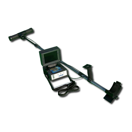
Page 42: Illustration 6.1: Control Unit With Power Supply And Probe
Via the display you can see the navigation menu and all recorded scans. The horizontal antennas like the 25 cm GPR probe have to be connected via the T-mount to the Telescopic rod assembly. Vertical probes like the Super Sensor can simply be held in your hand. OKM Ortungstechnik GmbH www.okmmetaldetectors.com... -
Page 43: Control Unit
Control Elements 6.1 Control Unit The control unit is the processing center of the eXp 4000. Via the control unit, various functions can be selected, all measured values can be recorded and stored. 6.1.1 Front View Figure 6.2 shows the front side of the control unit with its control elements. -
Page 44: Rear View
The connector for the headphones is used to plug in the delivered headphones enabling the user to hear an audio output. Via the connector for the USB cable the device can be connected to a computer via the USB cable. This is necessary to transfer data from the device to a computer. OKM Ortungstechnik GmbH www.okmmetaldetectors.com... -
Page 45: Operating Modes
7 Operating Modes HAPTER Operating Modes In this section you will learn more about the different operating modes of the eXp 4000. Every function is explained in its proper subsection. - Page 46 • Power off the device and shut down the integrated PC module. If you are connecting the optional FS-Thermoscan to the eXp 4000, there will be two more operating modes available. Without FS-Thermoscan those functions are inactive and not visible.
-
Page 47: Magnetometer
“Hot” targets. A hot target can be debris like cans, nails, screws, old automobile parts, etc... These should be cleared first. The magnetometer measures usually only near to the surface for quick hunts. OKM Ortungstechnik GmbH www.okmmetaldetectors.com... -
Page 48: Ground Scan
In the first submenu which is shown in figure 7.3, you can choose between the following alternatives: New Scan • Set up and record a new graphic. Browse Scans • See or delete stored graphics. Back To Main Menu • Finish Ground Scan and go back to the main menu. OKM Ortungstechnik GmbH www.okmmetaldetectors.com... -
Page 49: New Scan
The device will store the number of impulses and use it for all further scan lines on the same scan. By selecting the value 10, 20, ... or 50 you can preset the number of impulses you need in one measured line. OKM Ortungstechnik GmbH www.okmmetaldetectors.com... -
Page 50: Illustration 7.5: Zig-Zag Or Parallel
OK key. As soon as you press the OK button, begin walking immediately for the eXp 4000 is now recording data. As soon as your first scan line is finished a new message will appear, where you have to select "Yes" if you want to scan another measured line. -
Page 51: Browse Scans
7.8. Select the measurement which you like to see with the keys and . For the Illustration 7.8: Select Stored Measurement selected measurement the following options represented in figure 7.9 are provided. Illustration 7.9: Submenu: Browse Scans OKM Ortungstechnik GmbH www.okmmetaldetectors.com... - Page 52 The current selected measurement will be deleted, if you confirm the following message with "Yes". Following you will go back to the menu Ground Scan. Back To Ground Scan Menu • You go back to menu Ground Scan. OKM Ortungstechnik GmbH www.okmmetaldetectors.com...
-
Page 53: Metal Detector
Further information about the correct usage of the detector and the principle of discrimination you can find in section "Optional Equipment / DDV system" of this users manual! OKM Ortungstechnik GmbH www.okmmetaldetectors.com... -
Page 54: Discrimination
The figure 7.12 shows a typical signature of a ferromagnetic metal like iron. The signature includes a positive (red) and a negative (blue) amplitude. When looking closely you can see even 2 ferromagnetic signatures. The first signature starts with a positive amplitude and the second signature starts with a OKM Ortungstechnik GmbH www.okmmetaldetectors.com... -
Page 55: Empty Memory
If you confirm this option you will be asked again if you really want to delete all data. If you confirm now by pressing Yes all data will be deleted and cannot be rebuilt or transferred to a computer. OKM Ortungstechnik GmbH www.okmmetaldetectors.com... -
Page 56: Exit
Detailed information about this functionality is available in the user’s manual of FS-Thermoscan! 7.8 Thermo Scan This operating mode is only visible and usable if the optional device FS-Thermoscan is connected. Detailed information about this functionality is available in the user’s manual of FS-Thermoscan! OKM Ortungstechnik GmbH www.okmmetaldetectors.com... -
Page 57: Field Procedure
8 Field procedure HAPTER Field procedure This chapter gives practical instructions about the general procedure of scanning an area. The different scanning methods and procedures will be explained in detail. -
Page 58: General Scanning Procedure
(measure points), which are recorded during one scanning path can be adjusted individually depending on the size of your scan area (length of scanning path). 8.1.1 Scan Mode There are two general techniques to surveying an area with the eXp 4000: Zig-Zag •... -
Page 59: Regulation Of The Number Of Impulses Per Scanning Path
Starting from the second scanning path, the device now stops automatically after the assumed number of impulses has been reached. OKM Ortungstechnik GmbH www.okmmetaldetectors.com... - Page 60 Figure 8.4: Comparison of low and high number of impulses Do not hesitate to record more measurements with different numbers of impulses. For example you can scan a large area before doing a second detailed precision measurement. Especially if searching for OKM Ortungstechnik GmbH www.okmmetaldetectors.com...
-
Page 61: Special Advices For Field Procedure
Inform yourself about the area, where you are searching. Does it make sense to detect here? Are • there historical references which confirms your speculation? What type of soil is on this area? Are there good conditions for data recording? Is it allowed to search at this place (e.g. private property)? OKM Ortungstechnik GmbH www.okmmetaldetectors.com... -
Page 62: Orientation Of Probe
These stripes throughout a scan are commonly referred to as “Rotational Errors”. 8.2.2 Parallel or Zig-Zag? For skilled users of the eXp 4000 both scan modes are suitable. According to experience the best graphics has been received in the "Parallel" mode, because you are starting at the same point and traveling in the same direction. -
Page 63: Manual Or Automatic Impulse Mode
Get professional training. When you take advantage of receiving the training, either from the • factory or a qualified dealer, you will understand not only the use and operation of the OKM detector but also the software so much easier and be able to identify targets as well as errors. - Page 64 Rocky mountainous areas. Areas with many mountains are also riddled with patches of ◦ mineralization. Mountainous areas are created from faults in the earth and this is probably the biggest area for natural treasures as well as mineralization. OKM Ortungstechnik GmbH www.okmmetaldetectors.com...
-
Page 65: Optional Equipment
9 Optional Equipment HAPTER Optional Equipment Here you can find additional information on accessories that can compliment the basic unit. Keep in mind that the mentioned accessories are not included in the normal scope of delivery. -
Page 66: Super Sensor
The distance between the ground and lower part of the antenna should be about 10 cm, but can be enlarged depending on the terrain conditions. The orientation of the antenna should not be changed during the complete measurement! OKM Ortungstechnik GmbH www.okmmetaldetectors.com... -
Page 67: Ddv System
Before using the metal detector for the first time the DDV system has to be adjusted on the eXp 4000. If you purchased the DDV system together with the main unit the metal detector has already been OKM Ortungstechnik GmbH www.okmmetaldetectors.com... -
Page 68: Illustration 9.3: Calibration Of The Ddv System, Step 1
After finishing the calibration a visual signal (yellow light) should be visible on the screen. If the headphones are connected you will also hear an acoustical signal. The DDV system is now calibrated to work correctly on-site. OKM Ortungstechnik GmbH www.okmmetaldetectors.com... -
Page 69: Adjust The Discriminator
Please consider that you always should do the ground balance, which is explained in this following section. The indications from table 2 concern the use in normal type of soil. In extreme conditions (mineralisation, salt deposits, ... ) they can variate from this normal value. OKM Ortungstechnik GmbH www.okmmetaldetectors.com... -
Page 70: Ground Balance
In the following section you can find a list of all necessary working procedures to do a correct soil reconciliation: Power on the eXp 4000 and connect the DDV system. Adjust the discriminator on the material you like, see previous section. -
Page 71: Error Messages
10 Error Messages HAPTER Error Messages In this chapter you will find possible error messages which can appear during the work with the device. -
Page 72: Illustration 10.1: Only A Small Amount Of Memory Available
Also the automatic shutdown of the device may be affected. It is adviced to let the device check from the manufacturer to avoid further damages. Illustration 10.3: Internal Hardware Error OKM Ortungstechnik GmbH www.okmmetaldetectors.com... -
Page 73: Illustration 10.4: The External Power Supply Has To Be Charged
If the device itself is not able to power off, a message like in figure 10.6 is shown. In this case you simply power off your external power supply. Illustration 10.6: Shutting down the system is not possible OKM Ortungstechnik GmbH www.okmmetaldetectors.com...
Need help?
Do you have a question about the eXp 4000 and is the answer not in the manual?
Questions and answers