OKM FS Future Series User Manual
Hide thumbs
Also See for FS Future Series:
- User manual (72 pages) ,
- Manual (8 pages) ,
- User manual (18 pages)
Table of Contents
Advertisement
Advertisement
Table of Contents

Related Manuals for OKM FS Future Series


Summary of Contents for OKM FS Future Series
- Page 1 FS Future Series Rover UC Version: 3 User's Manual...
- Page 2 Any information contained in these operating instructions may be changed without prior notice. OKM does not make any warranty for this document. This also applies without limitation to implied assurances of merchantability and fitness for a specific purpose. OKM does not assume any responsability for errors in this manual or for any incidental or consequential damage or loss associated with the delivery, exploitation or usage of this material.
-
Page 3: Table Of Contents
7.3.1.2 Customized ........................7.3.2 Measurement Procedure ...................... 7.3.3 Saving a Scan ........................7.3.4 Scan Analysis ........................7.3.5 Data Transfer to PC (optional) ..................... 7.4 Pin Pointer ............................ 7.5 Open Scan ............................ 7.6 Settings ............................7.7 Information ..........................OKM GmbH www.okmmetaldetectors.com... - Page 4 9.2 Color Definition ..........................9.3 Establishing a background color ....................9.4 Search for anomalies ........................9.5 Void Interferences ........................9.6 Position of an anomaly within a graphic ..................9.7 Determining the difference from metal or mineral ..............OKM GmbH www.okmmetaldetectors.com...
- Page 5 Figure 8.4: Comparison of low and high number of impulses ..............48 Figure 8.5: Different walking speeds during scanning ................49 Figure 9.1: Ferromagnetic signal representation ................... 56 Figure 9.2: Comparisation between metal and mineralization ..............58 OKM GmbH www.okmmetaldetectors.com...
-
Page 7: Introduction
1 Introduction HAPTER Introduction... -
Page 8: Preface
1.1 Preface Dear customer, all of the engineers, sales, training and support staff at OKM GmbH would like to thank you for your purchase of the Rover UC. The Rover UC detector works on the principle of Electro-Magnetic Signature Reading (EMSR). Besides the detection of metallic objects this device is also capable of detecting natural features of the earth like formations of strata, cavities, voids, faults, ground water and other non-metallic objects. -
Page 9: Important Notes
1.2.4 Voltage The power supply should not be outside the indicated range of values. Use only approved chargers, batteries and rechargeable batteries which are included in the scope of delivery. Never use the 115/230 Volt mains supply. OKM GmbH www.okmmetaldetectors.com... -
Page 10: Data Safety
Note the color of the ground close to the surface. A red or reddish color of the ground is an indicator of rust traces. As regards the finds themselves, you should definitely pay attention to their shape. Curved OKM GmbH www.okmmetaldetectors.com... - Page 11 Moving such an object may cause those crystals to produce friction, leading to an explosion. If you come across such relics, mark the place and do not fail to report the find to the police. Such objects always pose a danger to the life of hikers, walkers, farmers, children and animals. OKM GmbH www.okmmetaldetectors.com...
-
Page 13: Technical Specifications
2 Technical specifications HAPTER Technical specifications... -
Page 14: Telescopic Probe
Free disk space ......................... min. 50 MB Working memory (RAM) ......................min. 256 MB Graphic card ..................min. 128 MB, OpenGL-compatible Operating system ..................... Windows 7 and higher GST = Ground Scan Technologie EMSR = Electro-Magnetic Signature Reading OKM GmbH www.okmmetaldetectors.com... -
Page 15: Scope Of Delivery
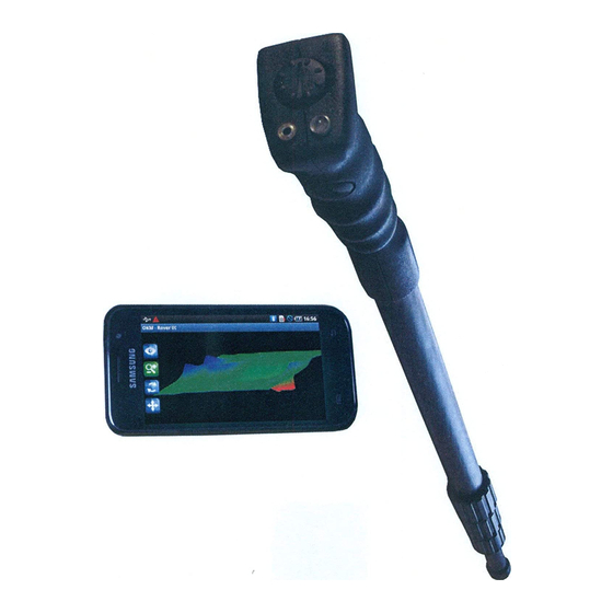
3 Scope of delivery HAPTER Scope of delivery... - Page 16 Bezeichnung Anzahl Controller (smartphone) Telescopic antenna User's manual Battery (type AA) Carrying bag "Visualizer 3D" software Table 1: Scope of delivery OKM GmbH www.okmmetaldetectors.com...
-
Page 17: Control Elements
4 Control elements HAPTER Control elements In this section, we would like for you to become familiar with the basic fundamental functions as well as the basic use and control of the instrument. All of the connections will also be explained here in detail. -
Page 18: Smart Phone
Every time the multifunction button is depressed the radio will seek the next available radio station. To switch the unit off, push and hold the multifunction button until the operational LED is no longer illuminated. OKM GmbH www.okmmetaldetectors.com... - Page 19 During a scan it is important that the lower part of the antenna be completely extended. Failure to extend the lowest portion of the antenna will impede signal quality. OKM GmbH www.okmmetaldetectors.com...
-
Page 21: Assembly
5 Assembly HAPTER Assembly This chapter explains how to assemble the unit and prepare it for scanning. -
Page 22: Figure 5.1: Insert The Batteries Into The Telescopic Antenna
Turn on the unit by pushing the multifunction button and wait for the LED. When it first turns on it will be green until it has established a connection with the Bluetooth in the smart phone. Figure 5.3: Turning on the telescopic antenna OKM GmbH www.okmmetaldetectors.com... -
Page 23: Download, Install And Activate Application
6 Download, install and activate application HAPTER Download, install and activate application This chapter explains how to download and install the application from the Google Play store as well as its activation. If you got your Rover UC with a pre-configured smartphone, you may skip this chapter. -
Page 24: Download And Installation
Therefor run the Google Play application from your smartphone, as shown in figure 6.1 and follow the instructions. If your account is ready, simply search for “okm rover uc” to find the application. Figure 6.1: Download and installation of Rover UC application Now click on “Install”... -
Page 25: Activation With Qr Code
If the code gets recognized by your application correctly, the activation will succeed and you may use your Rover UC. In case you are using a different Rover UC with this application at a later time, you will have to change your activation accordingly and repeat the activation process. OKM GmbH www.okmmetaldetectors.com... -
Page 26: Manual Activation
After entering all the requested information correctly, the activation will succeed and you can use your Rover UC. In case you are using a different Rover UC with this application at a later time, you will have to change your activation accordingly and repeat the activation process. OKM GmbH www.okmmetaldetectors.com... -
Page 27: Operating Modes
7 Operating modes HAPTER Operating modes In this section we will familiarize you with the various functions of the unit. All of the available functions and features will be explained in detail. -
Page 28: Figure 7.1: Starting The Application And Viewing The Main Menu
When this function is selected, it will display all of the scans that are in the memory. When you select a scan it can be viewed and analyzed. • Settings Adjust several options like language, color theme or GPS status. • Information This will show detailed information about the current software version and serial number. OKM GmbH www.okmmetaldetectors.com... -
Page 29: Establishing A Bluetooth Connection
Figure 7.2: Graphical depiction of a Bluetooth connection After the desired function is selected, the internal Bluetooth module should be automatically activated. In the event that it does not automatically activate, then a prompt will appear stating that it is not active OKM GmbH www.okmmetaldetectors.com... -
Page 30: Magnetometer
Most of the times this technique is used to detect small surface objects. This is helpful for clearing away objects, which can make a better scan when using the “3D Ground Scan” mode. OKM GmbH www.okmmetaldetectors.com... - Page 31 When you are finished with the “Magnetometer” mode, simply tap on the arrow to end the function and return back to the main menu on the smartphone. OKM GmbH www.okmmetaldetectors.com...
-
Page 32: Ground Scan
You can choose between the options “Default” and “Customized” as explained in the next sections. 7.3.1.1 Default This option is a predefined configuration (quick start) with following non-changeable settings: • Scan Mode: Parallel • Impulse Mode: Automatic • Field Length: Automatic OKM GmbH www.okmmetaldetectors.com... -
Page 33: Customized
The impulse mode sets the way how the individual measurements or scans are taken. The following options are available: Automatic ◦ The individual measured values are recorded in succession without a break and controlled by the software. There is no user interaction until the cycle is complete. OKM GmbH www.okmmetaldetectors.com... -
Page 34: Measurement Procedure
As soon as the connection is established, stand at the beginning of the first scan line in order to begin the scan. As indicated in figure 7.6 you have to press the trigger button of your Rover UC to scan the first line. OKM GmbH www.okmmetaldetectors.com... -
Page 35: Figure 7.7: "Zig-Zag" Scan In Operating Mode "3D Ground Scan
We recommend holding the unit at or approximately 10 cm above the ground. For more information on completing scans in various terrains please see Chapter 8 on page 45. OKM GmbH www.okmmetaldetectors.com... -
Page 36: Saving A Scan
Figure 7.9: Adding field dimensions to the current scan OKM GmbH www.okmmetaldetectors.com... -
Page 37: Scan Analysis
Reset view to default Rotate scan Zoom in and out Figure 7.10: Analysis controls in operating mode "3D Ground Scan" To end the scan analysis, push the back button of your phone to get back into the main menu. OKM GmbH www.okmmetaldetectors.com... -
Page 38: Data Transfer To Pc (Optional)
Figure 7.11: Locating the folder with scan images Figure 7.11 shows previously saved scan images within the Android folder system. The scan images are usually located in Device Storage > Documents > OKM > RoverUC > scans. The following folders are used by the Rover UC application: •... -
Page 39: Pin Pointer
Normally this technique is used after performing a scan using the “3D Ground Scan” function. This function is used once the primary target has been localized. The localized object can also be pin pointed with this particular function. OKM GmbH www.okmmetaldetectors.com... -
Page 40: Figure 7.14: Ferromagnetic Signature
Non-metallic Objects All other objects are non-metallic. When you pass over an object (e.g. a tunnel or disturbance in the ground) you will see only a negative (blue) signal Figure 7.16: Non-metallic object signature OKM GmbH www.okmmetaldetectors.com... -
Page 41: Open Scan
7.6 “Settings“ on page 42), you can start Google Maps or any other appropriate application. • Delete Scan Select this item if you like to delete the scan image from your smartphone. To return to the previous screen press on the back button of your smartphone or use the arrow . OKM GmbH www.okmmetaldetectors.com... -
Page 42: Settings
If this option is enabled, GPS data will be recorded along to the actual measurement values. This can be beneficial, if you like to store location data with your scan data for future reference. • Color themes You can choose between three predefined color themes: Apricot, Grey and Black. OKM GmbH www.okmmetaldetectors.com... -
Page 43: Information
Operating modes 7.7 Information When selecting “Information” from the main menu, a new screen will appear showing the software version as well as the device's serial number, that is necessary for any support requests. Figure 7.19: Information screen OKM GmbH www.okmmetaldetectors.com... -
Page 45: Field Procedure
8 Field procedure HAPTER Field procedure This chapter gives practical instructions about the general procedure of scanning an area. The different scanning methods and procedures will be explained in detail. -
Page 46: General Scanning Procedure
The starting position of two scanning paths is always on the same side of the measured area. You will only record data in one way and in one direction, while you should return and walk back to the starting position of the next scanning path without recording data. Figure 8.2 represents both techniques schematically. OKM GmbH www.okmmetaldetectors.com... -
Page 47: Regulating The Length Of A Scanning Path
PC, to receive all measured data correctly from your measuring instrument! There is no special rule for selecting the right length but there are different aspects which should be considered. These are some considerations OKM GmbH www.okmmetaldetectors.com... -
Page 48: Figure 8.3: Effects Of Changing The Number Of Impulses And Their Distance
Every scan line should be measured at the same speed as the previous line. Figure 8.5 shows what can happen, if you walk at different speeds during your scan. OKM GmbH www.okmmetaldetectors.com... -
Page 49: Special Advices For Field Procedure
All further control measurements should be adjusted individually. • What is the form of the object you search? If you are looking for an angular metal box, the identified object in your graphic should have a form according to this. OKM GmbH www.okmmetaldetectors.com... -
Page 50: Orientation Of Probe
Especially in uneven territories like mountain sides, acclivities or other inclined layers the parallel mode is preferred. When it comes to speed, the experienced user will very often use the Zig-Zag mode for the initial scan to determine if there are anomalies in the area worth further research. OKM GmbH www.okmmetaldetectors.com... -
Page 51: Manual Or Automatic Impulse Mode
Get professional training. When you take advantage of receiving the training, either from the factory or a qualified dealer, you will understand not only the use and operation of the OKM detector but also the software so much easier and be able to identify targets as well as errors. - Page 52 Rocky mountainous areas. Areas with many mountains are also riddled with patches of mineralization. Mountainous areas are created from faults in the earth and this is probably the biggest area for natural treasures as well as mineralization. OKM GmbH www.okmmetaldetectors.com...
-
Page 53: General Data Analysis
9 General Data Analysis HAPTER General Data Analysis In this chapter we will give you general information on how to analyze the obtained data. -
Page 54: Looking At The Graphic For The First Time
Because the unit does work with the naturally occurring magnetic fields, the poles may actually reverse so red is blue and blue is red. OKM GmbH www.okmmetaldetectors.com... -
Page 55: Color Definition
“Real Targets Don't Move!”. If in your second and third control scans you realize that nothing is staying in the same place, most likely there is nothing there and you are looking at a patch of mineralized soil. OKM GmbH www.okmmetaldetectors.com... -
Page 56: Establishing A Background Color
Now there is also the possibility that you have a scan that has a lot of different colors all at the same time. This usually occurs when one is looking at completely normal soil without any significant properties. 9.5 Void Interferences There are outside forces which can cause interference to your signal. For example some of these OKM GmbH www.okmmetaldetectors.com... -
Page 57: Position Of An Anomaly Within A Graphic
When conducting a control scan be sure that your entire work area is clear from any unwanted debris. Using the “Magnetometer” now is a wise choice to ensure that there is not any unwanted debris. Also it is OKM GmbH www.okmmetaldetectors.com... -
Page 58: Figure 9.2: Comparisation Between Metal And Mineralization
“Parallel” mode to lower the chance of error. Figure 9.2: Comparisation between metal and mineralization In figure 9.2 there is an actual object on the scan on the left whereas on the right is mineralized soil. OKM GmbH www.okmmetaldetectors.com...
Need help?
Do you have a question about the FS Future Series and is the answer not in the manual?
Questions and answers