
Subscribe to Our Youtube Channel
Related Manuals for Still EXU-H-18


Summary of Contents for Still EXU-H-18
- Page 1 Original instructions Electric pallet truck EXU - H-18 EXU - H-20 0161 0162 2354 2356 1152 801 15 17 EN - 02/2021 - 14...
- Page 3 Preface Address of manufacturer and contact details STILL GmbH Berzeliusstraße 10 22113 Hamburg, Germany Tel. +49 (0) 40 7339-0 Fax: +49 (0) 40 7339-1622 Email: info@still.de Website: http://www.still.de 1152 801 15 17 EN - 02/2021 - 14...
-
Page 5: Table Of Contents
Table of contents Introduction Your industrial truck ........... General . - Page 6 Table of contents Overviews Truck overview............Overview .
- Page 7 Table of contents Transporting loads ........... . Load handling safety rules.
- Page 8 Table of contents Maintenance operations that do not require special training ..... . Ordering spare parts and consumables ........Maintenance safety guidelines .
- Page 9 Table of contents Technical specifications EXU-H datasheet........... . . Technical datasheet EXU-H 20S (option) .
-
Page 11: Introduction
Introduction... -
Page 12: Your Industrial Truck
Introduction Your industrial truck Your industrial truck General The truck described in these operating instruc- tions corresponds to the applicable standards and safety regulations. If the truck is to be operated on public roads, it must conform to the existing national regula- tions for the country in which it is being used. -
Page 13: Ce Labelling
Introduction Your industrial truck CE labelling The manufacturer uses CE labelling to indi- cate that the truck complies with the standards and regulations valid at the time of marketing. The supplied EC declaration of conformity confirms this. The CE labelling is attached to the nameplate. -
Page 14: Ec Declaration Of Conformity
Introduction EC declaration of conformity EC declaration of conformity Declaration STILL GmbH Berzeliusstrasse 10 22113 Hamburg GERMANY We declare that the machine Industrial truck according to these operating instructions Model according to these operating instructions conforms to the latest version of the Machinery Directive 2006/42/EC. -
Page 15: Identification Label
Introduction Identification label Identification label NOTE Indicate the serial number for all technical en- quiries. Model Manufacturer Serial number Year of manufacture Unladen weight (without battery) in kg Maximum battery weight Minimum battery weight (for a lithium-ion battery, the weight of the ballast container is included) Additional weight (ballast weight) in kg Nominal motor power (kW) -
Page 16: Eco-Design Requirements For Electric Motors And Variable Speed Drives
Eco-design requirements for electric motors and variable speed drives Internet address and QR code The information can be accessed at any time by pasting the address https://m.still.de/vdma in a web browser or by scanning the QR code. Eco-design requirements for electric motors and variable... -
Page 17: Spare Parts List
Spare parts list The spare parts list can be downloaded by en- tering the address https://sparepartlist.still.eu into a web browser or by scanning the QR code displayed to the side. When the web page is open, please type in... -
Page 18: Permissible Use
Introduction Permissible use Permissible use The truck described in these operating instruc- The purpose of obtaining these permissions in tions is suitable for lifting and transporting advance is to limit danger as far as possible. loads. The truck should only be used for the purpo- ses for which it was designed, as described in these instructions. -
Page 19: Unauthorised Use
Introduction Unauthorised use Unauthorised use Any danger caused as a result of unauthor- Transporting people is prohibited. ised use becomes the responsibility of the op- The forklift truck should not be used in areas erator or driver and not that of the manufactur- where there is a risk of fire, explosion or corro- sion, or in areas that are particularly dusty. - Page 20 Introduction Disposing of components and batteries 1152 801 15 17 EN - 02/2021 - 14...
-
Page 21: Safety
Safety... -
Page 22: Safety Regulations
Safety Safety regulations Safety regulations Regular checks and technical inspections These operating instructions, which come with ● the truck, must be communicated to all those Recycling of lubricants, oils and batteries ● concerned and in particular to personnel re- Residual risks. ●... -
Page 23: Safety Regulations For Handling Consumables
Safety Safety regulations for handling consumables Safety regulations for handling consumables Permissible consumables Refer to the maintenance data table for the WARNING permissible substances necessary for opera- Consumables can be dangerous. tion. It is necessary to follow the safety regulations when handling these substances. -
Page 24: Hydraulic Fluid
Safety Safety regulations for handling consumables Hydraulic fluid WARNING ENVIRONMENT NOTE During operation of the forklift truck, hy- draulic fluids are pressurised and are Hydraulic fluid is a water-polluting substance! hazardous to your health. Always store hydraulic fluid in containers com- –... -
Page 25: Disposal Of Consumables
Safety Safety regulations for handling consumables Disposal of consumables Any spillage of fluids such as hydraulic oil, ● ENVIRONMENT NOTE brake fluid or gear lubricant oil must be im- mediately soaked up with an oil-binding Materials that have to be disposed of following agent. -
Page 26: Emissions
Safety Emissions Emissions Noise emission values Calculated during the test cycle performed in accordance with standard EN12053. Acoustic pressure level in the driver's compartment EXUH 18, EXUH 20, EXUH 20S 59 dB (A) Uncertainty ± 2.5 dB (A) NOTE Lower or higher noise values may occur when using industrial trucks, e.g. -
Page 27: Residual Dangers, Residual Risks
Safety Residual dangers, residual risks Residual dangers, residual risks Falling, tripping etc. when moving on the in- Despite all operational precautions and com- ● dustrial truck, especially in the wet, with pliance with standards and rules, the possibili- leaking consumables or icy surfaces. ty of additional risks when using the truck can- Loss of stability due to the load being unsta- not be entirely excluded. -
Page 28: Definition Of Responsible Persons
Safety Definition of responsible persons Definition of responsible persons Operating company The operating company is the natural or legal The operating company is responsible for the person or group who operates the truck or on scheduling and correct performance of regular whose authority the truck is used. - Page 29 Safety Definition of responsible persons Prohibition of use by unauthorised per- When leaving the truck, the driver must secure it against unauthorised use. sons The driver is responsible for the truck during working hours. He must not allow unauthor- ised persons to operate the truck. 1152 801 15 17 EN - 02/2021 - 14...
-
Page 30: Safety Tests
Safety inspection based on time and ex- traordinary incidents The operating company (see chapter entitled "Definition of responsible persons") must en- STILL GmbH Hamburg sure that the truck is checked by a specialist at least once a year or after noteworthy inci- Regelmäßige Prüfung dents. - Page 31 Overviews...
-
Page 32: Overviews
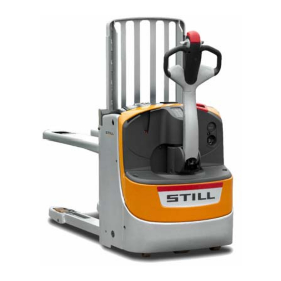
Overviews Truck overview Truck overview Overview Backrest* Drive wheel Tiller Traction motor Battery connector handle (emergency stop) Pump unit Battery cover Electromagnetic brake Ignition key Horn Traction controller Lift cylinder Fork arms Digicode* Load wheels Load arms Stabiliser wheels Platform* *Option 1152 801 15 17 EN - 02/2021 - 14... -
Page 33: Control And Display Components
Overviews Control and display components Control and display components Tiller Handle Travel throttle valve Load arm lifting Anti-crush safety feature Proportional lowering of fork arms Travel throttle valve Proportional lifting of fork arms Lowering the load arms Horn 1152 801 15 17 EN - 02/2021 - 14... -
Page 34: Battery Charge Indicator
Overviews Control and display components Battery charge indicator COMMENTS / SCREEN DESCRIPTION EXPLANATION MESSAGES 91% - 100%: 10 bars 1% - 10%: 1 bar Full charge: 100% 0%: 1 flashing bar (lift func- Battery charge level repre- Low charge: 10% Dis- tion not permitted). - Page 35 Overviews Control and display components COMMENTS / SCREEN DESCRIPTION EXPLANATION MESSAGES Switched off: truck switched Green indicator light Switched on: truck switched These codes help the After Sales Service to decide on Breakdown code E3 294 the appropriate response from the service engineer Fault or brake wear (air gap) Do not operate the truck - The meter runs from when...
-
Page 36: Digicode Option (Lfm Go)
Overviews Control and display components Digicode option (LFM Go) Switch ON (operating mode) Key fault or incorrect code Switch OFF and awaiting code Time delay of automatic switch-off Programming mode active Operation Key in LED status Notes ○ red off ● continuous * 0 0 0 0 0 # green (1)(correct PIN) 0 0 0 0 0... - Page 37 Overviews Control and display components PROGRAMMING (truck switch OFF only (2)) Power switches off auto- ● red flashing ● green Activating the au- matically after 10 mins flashing (5) (5 s before * * 2 * 1 # tomatic switch-off (600 s by default) if the switch-off) truck is not being used.
-
Page 38: Markings
Overviews Markings Markings Location of markings Brand label Warranty label (for Germany only) on the in- EXU H 18 model label side of the tiller EXU H 20 model label Cold store label Identification label Capacity label Slinging label "Automatic lifting and lowering" label (option) ELECTRICAL DANGER label PIEK label (option) on the outside of the tiller DANGER INSTRUCTIONS label... -
Page 39: Serial Number
Overviews Markings Serial number xx xxxx x xxxxx NOTE Indicate the serial number for all technical en- quiries. The serial number contains the following infor- mation: 1 Production location 2 Type 3 Year of production 4 Count number 7090_921-004 1152 801 15 17 EN - 02/2021 - 14... - Page 40 Overviews Markings 1152 801 15 17 EN - 02/2021 - 14...
-
Page 42: Description
Description Description Two types of battery removal are available The pallet trucks EXU-H18 and EXU-H20 are made up of a high lift (fork arm) and a low lift Vertical removal (2Pzs BS) on EXU-H18 ● (load arm). and (2Pzs DIN) on EXU-H20 Side removal (2Pzs DIN) available as an The fork arms are used to level the pallet thus ●... - Page 43 Description electromagnetic safety device, controlled by a 3-position ignition key (stop/tortoise/hare) ● ● the upper or lower position of the tiller a tiller with the following controls: forward/ ● electromagnetic parking, applied when sup- reverse travel, accelerator, lifting/lowering ● ply is cut. of the fork arms (proportional control), lift- ing/lowering of the load arms, horn and safety reverser...
-
Page 44: List Of Checks Prior To Start-Up
List of checks prior to start-up List of checks prior to start-up – Damaged or missing stickers must be re- WARNING placed in compliance with the marking posi- Damage or other defects on the truck or attachments tion table. (special equipment) can result in accidents. –... -
Page 45: Checks And Actions Prior To Commissioning
Checks and actions prior to commissioning Checks and actions prior to commissioning Charging a Gel or Lead battery (wall-mounted charger) – Open the cover. – Leave it open. – Remove the battery disconnection handle (1) from the truck plug (2). –... -
Page 46: Checking The Emergency Stop
Checks and actions prior to commissioning Checking the emergency stop – Pull the emergency stop handle (4) up- wards. – The power supply to the machine is cut off. – The electrical controls and motors are disa- bled. – The electromagnetic brake is applied. –... -
Page 47: Checking The Anti-Crush Safety Device
Checks and actions prior to commissioning Checking the anti-crush safety de- vice Anti-crush safety function The machine moves in the opposite direction when the anti-crush button (2) is pressed. If the truck is being operated in narrow areas (such as in a lift for example), the operator may get stuck against the wall if care is not taken. -
Page 48: Truck Operating Instructions
Truck operating instructions Truck operating instructions The trucks are designed for indoor and out- Speed must be reduced when moving over door use in non-hazardous atmospheres. The obstacles to prevent the truck from becoming temperature should be between -10°C and unbalanced and vibrations in the forklift opera- +45°C and the relative humidity of the air less tor's arms. - Page 49 Truck operating instructions Before using a side access truck, check that the bat- CAUTION tery is correctly locked. Risk of injury 1152 801 15 17 EN - 02/2021 - 14...
-
Page 50: Driving
Driving Driving Driving safety guidelines Never sit on the truck to drive it Behaviour when driving ● The truck must not be used as a stepladder ● Operators must obey the same rules within This truck is not designed to transport peo- ●... -
Page 51: Defining Directions
(default code = 00000). NOTE With the digicode option, when the key is turned to the 0 position the truck is in tortoise mode. The truck will still function if the key is removed. 1152 801 15 17 EN - 02/2021 - 14... - Page 52 Driving Selecting the driving mode NOTE The ignition key may be turned to two different positions to choose the driving mode. "Tortoise" position (2) : gentle acceleration and deceleration; max. speed: 4 km/h "Hare" position (3) : strong acceleration and deceleration;...
-
Page 53: Driving
Driving Driving – Turn the ignition key to the Tortoise sition (slow acceleration and deceleration) or the position (faster acceleration Hare and deceleration). – Lower the tiller in (2) zone. NOTE The truck is in the drive position in the (2) po- sition. -
Page 54: Driving On Upward And Downward Slopes
Driving Driving on upward and downward slopes Slopes should always be approached with the load facing towards the top of the slope. Only slopes marked as clear traffic routes compati- ble with the truck's technical specifications can be safely used. DANGER The operator must ensure that the ground is clean and has a non-slip surface. -
Page 55: Braking
Driving Braking WARNING The quality of the floor surface affects the braking distance of the truck. To be taken into consideration when driving. Gentle braking – During operation, release throttle (2) or (3). Moderate braking – Switch throttle (2) or (3) in the opposite di- rection of travel. -
Page 56: Creep Speed Function
Driving Creep Speed function This function makes it possible to manoeuvre the truck in confined spaces. The tiller remains in the vertical position. – Press the Creep Speed button (1) (tortoise icon) on the tiller. Hold the button down. –... - Page 57 Driving Timeout can be adjusted. Please call the Af- ter-Sales Service Centre. 1152 801 15 17 EN - 02/2021 - 14...
-
Page 58: Operating The Fleetmanager™ Option
Operating the FleetManager™ option Operating the FleetManager™ option Description of the FleetManager option The FleetManager option allows you to control GSM: Global System for Mobile Communi- access to the truck. The option is a fleet man- cation agement system. Shock sensor You can access the system: Either by using a keypad This sensor allows you to record the shocks... -
Page 59: Commissioning A Truck Equipped With The Fleetmanager™ Option
Operating the FleetManager™ option Commissioning a truck equipped with the FleetManager™ option Commissioning a truck equipped with a keypad or an electronic key – Turn the switch key to start the truck. – Enter the PIN code on the keypad. The PIN code consists of five to eight digits. -
Page 60: Fleetmanager™ Option: Colour Code For The Leds
Operating the FleetManager™ option FleetManager™ option: Colour code for the LEDs The LEDs can have different statuses and dif- ferent colours. Below is the list of the most common messages and their meanings. Malfunction Cause Solution LED status Signal transmitter LED 1 LED 2 Reading device... - Page 61 Operating the FleetManager™ option Malfunction Cause Solution LED status Signal transmitter LED 1 LED 2 Flashes quickly Lit continuously A shock has oc- Reset the shock Red colour Green colour curred The truck is The truck is con- switched on but is nected via a Blue- not moving.
-
Page 62: Disconnecting A Truck Equipped With The Fleetmanager™ Option
Operating the FleetManager™ option Disconnecting a truck equipped with the FleetManager™ option NOTE Operators must not log off intentionally while driving. WARNING Access to the truck must be disabled. Unauthorised users are not allowed to use the truck. Disconnecting a truck equipped with a ... - Page 63 Operating the FleetManager™ option Disconnecting a truck equipped with an RFID reading device – Park the truck in a safe place. – Briefly place the RFID card or the RFID transponder (4) in front of the reading de- vice (3). The LED (1) lights up for a second (red col- our).
-
Page 64: Transporting Loads
Transporting loads Transporting loads Load handling safety rules WARNING Closely follow the following instructions before pick- ing up loads. Never touch or stand on moving parts of the truck (e.g. lifting device, pushing devices, work installations or devices for picking up loads). WARNING Take care not to trap hands or feet when operating the truck. -
Page 65: Transporting Pallets Or Other Containers
Transporting loads Transporting pallets or other con- tainers As a general rule, loading units must be trans- ported one by one (e.g. pallets). Transporting several loading units at a time is only author- ised: when the safety preconditions are fulfilled. ●... -
Page 66: Lifting
Transporting loads Lifting WARNING Risk of injury The safety regulations must be strictly adhered to. It is strictly forbidden to touch or stand on moving parts (e.g. lifting device, pushing devices, work in- stallations, load lifting devices). The pallet truck has two lift systems: 1-Main lift (forks) ... -
Page 67: Main Lift-Base Lift
Transporting loads Main lift-Base lift Main Lift Fork arms lifting – Press the proportional control button (2). Fork arms lowering – Press the proportional control button (1). NOTE A groove (3) is present on each side of the button. This helps you to feel the button and to identify it even if there is not much light. - Page 68 Transporting loads CAUTION Risk of falling Be careful not to touch adjacent loads or loads posi- tioned at the side or in front of the load being han- dled. The loads are to be stacked so that they are aligned with a small space between each of them and so that they do not catch each other.
- Page 69 Transporting loads Reverse travel is used for setting down the ● load Adjust your speed. Do not drive with an unstable load ● Raise the forks slightly in order to pass ob- ● stacles Be careful of low passageways, low door- ●...
-
Page 70: Using Autolift (Option)
Transporting loads Using Autolift (option) NOTE Training on how to use this option is required before use. WARNING Risk of accident! Ensure that there is nobody in the work area. Description of the Autolift option The Autolift option enables automatic lifting and automatic lowering of the forks. - Page 71 Transporting loads The enclosure for the Autolift option The enclosure for the Autolift option consists An emergency off switch (1) ● An activation button (2) ● A selector switch for stopping/automatic lift- ● ing/automatic lowering (3) Loading and unloading DANGER In case of danger, press the emergency off switch (1).
- Page 72 Transporting loads – Press the activation button (2) The pallet lifts automatically as the packets are unloaded. The upper level of the load is aligned at 800 mm from the ground. Two gauges are used for the levelling. 1152 801 15 17 EN - 02/2021 - 14...
-
Page 73: Using The Folding Platform (Option)
Using the folding platform (option) Using the folding platform (option) There are two positions for the folding platform (1): Position A: platform raised ● Position B: platform lowered ● In pedestrian mode, the platform is raised. 2276 The maximum authorised speed is 6 km/h. In ride-on mode, the platform is lowered. -
Page 74: Cold Store Usage (Option)
Cold store usage (option) Cold store usage (option) Designation Your truck is fitted with special equipment for use in cold stores. It can be used for two oper- ating ranges and carries a cold store label. The cold store equipment for the truck con- sists of using specialised oils (for the hydraulic installation and the gears) suitable for cold stores. - Page 75 Cold store usage (option) – Drive the truck for approximately 5 minutes and operate the brakes several times to en- sure the truck operates safely. – Operate all the lifting functions several times. This warming up phase is required to allow the oil to reach operating temperature.
-
Page 76: Stopping The Truck
Stopping the truck Stopping the truck – Switch off the ignition then remove the key WARNING or press the button on the digicode for Do not stop the truck on a slope, or if this is absolute- 2 seconds. ly necessary, make sure it is safely secured using chocks. -
Page 77: Handling The Battery
Handling the battery Handling the battery Battery type Trucks can be fitted with different types of bat- tery. Comply with the information indicated on your battery's type plate, as well as with its features. WARNING The weight and size of the battery influence the sta- bility of the truck. -
Page 78: Opening/Closing The Battery Cover
Handling the battery Parking the truck securely When the battery is being worked on, the truck must be parked safely. The truck can only be restarted when the covers and connectors have been put back in the operating position. Opening/closing the battery cover Opening –... -
Page 79: Charging The Battery Using An External Charger
Handling the battery Charging the battery using an exter- nal charger CAUTION The battery may be damaged if discharged beyond a given limit. – Immediately charge the battery. – Safely park the truck – Before charging, check the condition of the battery cable and the charging cable and replace these cables if necessary. -
Page 80: On-Board Charger
Handling the battery On-board charger Precautions for installation and use Nominal battery volt- The on-board charger means you no longer Tolerance on the volt- have to use a charging room. In fact, this age of bearing U charger can be connected to any 2P+T 230 V 16 A socket. -
Page 81: Using The Charger
Handling the battery When the charger is neither connected to Protection during charging ● the mains nor the battery, the "contact A" Mains micro-break protection and "contact B" outputs are electrically insu- lated from one another. If the mains power is cut off, all the charging When the charger is connected to the bat- ●... - Page 82 Handling the battery Phase Green LED Red LED CAUTION Battery polari- Do not disconnect the battery connector during ty reversed charging (green indicator light flashes). Selector in The truck cannot be operated during charging. neutral posi- Flashing Flashing tion The on-board charger is intended for recharg- ing the battery.
-
Page 83: Gel Or Lead Batteries: Adjusting The On-Board Charger
Handling the battery Gel or Lead batteries: Adjusting the on-board charger When the truck is delivered with its battery, ● the charger settings are adjusted in the fac- tory. The adjustment depends on the selected ● battery. Charging curve selector ... - Page 84 Handling the battery – Open the battery compartment (1). – Unplug the battery connector (2). In order to avoid short-circuits, it is recommen- ded that batteries with polar terminals or un- protected connections be covered with a rub- ber mat. –...
-
Page 85: Gel And Lead Side Access Batteries: Changing The Battery Using A Trolley
Handling the battery Gel and lead side access batteries: changing the battery using a trolley Positioning the truck – On level ground, move the pallet truck close to the trolley (2). – Align the battery compartment with the empty space on the trolley (1). –... - Page 86 Handling the battery – Turn the retaining lock of the charged bat- tery. INSTALL THE CHARGED BATTERY: – Fully insert the charged battery in its com- partment. – Fold the stop down. – Lift the lever slightly and then unlock the notch.
-
Page 87: Side Access Battery: Changing The Battery Using A Moveable Support
Handling the battery Side access battery: changing the battery using a moveable support CAUTION During operations to fit the battery, keep your fingers away from moving parts to avoid any risk of them be- ing trapped. We recommend the use of gloves. Positioning the truck –... - Page 88 Handling the battery CAUTION Before using the machine, ensure that the battery is correctly installed and that its cover is correctly locked. 1152 801 15 17 EN - 02/2021 - 14...
-
Page 89: Handling The Truck In An Emergency
Handling the truck in an emergency Handling the truck in an emergency Towing the truck It is not possible to tow the truck with no elec- trical function. The electromagnetic brake re- mains in the closed position. You may tow the truck with a rigid connection (tow bar) if the truck to be towed can no longer be braked. - Page 90 Handling the truck in an emergency – Unscrew and remove the two screws to re- establish brake operation. – Close the hood of the technical compart- ment. 1152 801 15 17 EN - 02/2021 - 14...
-
Page 91: Handling The Truck In Specific Situations
Handling the truck in specific situations Handling the truck in specific situations Slinging the truck CAUTION Risk of injury Use a hoist and hooks of sufficient capacity. Refer to the load weight shown on the truck's data plate. – Attach a sling or a hook to the 2 points indi- ... -
Page 92: Transporting The Truck
Handling the truck in specific situations Jacking The truck must be jacked and chocked in or- der to perform certain maintenance opera- tions. Always make sure: To use a jack with an adequate lifting ca- ● pacity, Make sure that the truck is parked on level ●... -
Page 93: Transporting The Machine
Handling the truck in specific situations The truck must be suitably protected from the DANGER effects of the weather during transport and Danger of death. storage. Do not stand within the hoist's operating radius or To load or unload the truck, use an inclined below the lifted truck. - Page 94 Handling the truck in specific situations 1152 801 15 17 EN - 02/2021 - 14...
-
Page 95: Maintenance
Maintenance... -
Page 96: General Maintenance Information
Maintenance General maintenance information General maintenance information General The following instructions contain all the infor- mation required for servicing your truck. Carry out the various maintenance work in compli- ance with the maintenance plan. This will en- sure that your truck is reliable and in good working order and that the warranty remains valid. -
Page 97: Servicing And Maintenance Personnel Training And Qualification
Maintenance General maintenance information Servicing and maintenance personnel training and qualification Truck maintenance must only be carried out The person responsible for carrying out the in- by qualified and authorised personnel. spection must have sufficient knowledge and experience to be able to assess the condition The annual inspection for prevention of acci- of the truck and the efficiency of the protective dents at work must be carried out by a person... -
Page 98: Maintenance Safety Guidelines
Maintenance Maintenance safety guidelines Maintenance safety guidelines Servicing and maintenance measures To avoid accidents during servicing and main- – Ensure that there is no risk of the truck tenance operations, take all necessary safety moving or starting up unexpectedly. For this measures. -
Page 99: Technical Specifications For Inspection And Maintenance
Maintenance Technical specifications for inspection and maintenance Technical specifications for inspection and maintenance Unit Item/Lubricant Capacities/Setting values Maximum level 0.97 l Main hydraulic system Hydraulic oil Minimum level 0.92 l Reducer Reducer oil 0.9 litre maximum Traction and pump motor Fuses Power 125 A, Quantity: 1 Control cable harness... -
Page 100: Access To The Technical Compartment
Maintenance Access to the technical compartment Access to the technical com- partment – Fully raise the pallet truck's load arms to fa- cilitate these operations. CAUTION Before removing anything from the truck – Turn the key switch off. – Pull the battery connector handle (emergency stop handle). - Page 101 Maintenance Access to the technical compartment Opening the front cover After removing the lower cover: – Unscrew the 4 screws (2) that hold the cov- er in place. Accessing the pump unit After removing the front cover: – Remove the plastic cover by unscrewing ...
- Page 102 Maintenance Access to the technical compartment – Then remove the mounting bracket (4) 1152 801 15 17 EN - 02/2021 - 14...
-
Page 103: Accessing The Reducer And The Brake
Maintenance Accessing the reducer and the brake Accessing the reducer and the brake To access the reducer and the brake: – Turn the tiller to the right or left-hand stop. – Unscrew the 2 screws (3) – Unscrew the 2 screws (2) located either ... -
Page 104: Maintenance Plan As Required
Maintenance Maintenance plan as required Maintenance plan as required Depending on the application, environmental conditions and driving style, the following proce- dures should be carried out as required Preparation Cleaning the truck Chassis and equipment Checking the brake operation Checking the condition of the roller frame Wheels Checking the wheels for wear Electrical equipment... -
Page 105: 1000-Hour/Annual Maintenance Plan
Maintenance 1000-hour/annual maintenance plan 1000-hour/annual maintenance plan Maintenance operations every 1000 hours Depending on the application, environmental conditions and driving style, the following proce- dures should be carried out every 1000, 2000, 4000, 7000 and 8000 hours Preparation Clean the truck (if necessary) Check the error codes (using the diagnostic tool) Traction motor Check that the cables and bundling are in good condition... -
Page 106: 3000-Hour Maintenance Plan
Maintenance 3000-hour maintenance plan 3000-hour maintenance plan Additional maintenance operations every 3000 hours Depending upon use, environmental conditions and driving style, the following procedures must be performed every 3000, 6000 and 9000 hours Information Carry out all 1000-hour maintenance work Transmission Drain the transmission gear oil Hydraulic system... -
Page 107: Chassis, Bodywork And Fittings
Maintenance Chassis, bodywork and fittings Chassis, bodywork and fittings Clean the truck Washing instructions – Always park the truck as specified. – Disconnect the battery connector (4). CAUTION – Disconnect the battery connector when washing the truck. Washing the exterior of the truck WARNING Do not use inflammable fluids for cleaning. -
Page 108: Clean The Battery And Its Compartment
Maintenance Chassis, bodywork and fittings After washing the truck. – Dry the truck thoroughly (eg with com- pressed air). – Take the truck back into operation accord- ing to instructions. If moisture has penetrated the motors despite the precautionary measures, dry them first with compressed air;... -
Page 109: General Information On Battery Maintenance
Maintenance Chassis, bodywork and fittings – Pump off any electrolyte that may have spil- led between the cells. – Clean the top of the cells with a damp cloth. CAUTION In case of heavy sulphate build-up or excessive elec- trolyte spillage, please contact the After-Sales Serv- ice Centre. -
Page 110: Folding Platform Maintenance
Maintenance Chassis, bodywork and fittings CAUTION Do not obstruct the ventilation. Allow the charger to cool down for 10 minutes after charging is complete before touching it. Do not use the charger out of the truck. Folding platform maintenance The folding platform must be checked regular- ly. -
Page 111: Steering And Wheels
Maintenance Steering and wheels Steering and wheels Servicing wheels and rollers Check the tyres and the wear on the wheels and rollers The tyre tread on the drive wheel (1), the sta- bilising wheel (2) and the rollers (3) must not be damaged. -
Page 112: Maintaining The Reinforced Stabilisers (Option)
Maintenance Steering and wheels – Tighten the clevis (1) using a 14 mm Allen key to lower the wheel or loosen the clevis (1) using a 14 mm Allen key to lift the wheel – After adjustment, lock the clevis (1) with the lock nut (2) tightened to a torque of 35 Nm NOTE To screw, unscrew or lock the clevis (1) al-... -
Page 113: Regular Maintenance Of The Transmission Gear
Maintenance Steering and wheels Regular maintenance of the trans- mission gear To increase the service life of the transmission gear, 2 grease nipples (1) have been added to its turntable. It is therefore possible to regularly lubricate the transmission gear. NOTE Use the lubricants recommended by the man- ufacturer. -
Page 114: Electrical Equipment
Maintenance Electrical equipment Electrical equipment Servicing the electrical system Checking the cable and fuse connection mountings WARNING Stop the truck and disconnect the battery before car- rying out the following checks. – Remove the front hood. – Check the condition of the fuses (1). –... -
Page 115: Battery Maintenance
Maintenance Electrical equipment Battery maintenance The operations described below relate to lead batteries with liquid electrolyte. For batteries with gel electrolyte, which are said to be "maintenance-free", please refer to the manu- facturer's instructions. WARNING Avoid contact with the acid. Do not create a short-cir- cuit. - Page 116 Maintenance Electrical equipment CAUTION Only top up with demineralised water. Never top up before charging (risk of overflow). Do not overfill the cells. NOTE For more information, refer to the instructions supplied with the battery. Electrical equipment: checking the elec- ...
-
Page 117: Checking The Condition Of Cables, Terminals And Battery Connector
Maintenance Electrical equipment Checking the condition of cables, terminals and battery connector – Check that the cable insulation is undam- aged and that there are no signs of over- heating at the connections. – Check that the "+" and "-" output terminals are not sulfated (presence of white salt). -
Page 118: Cleaning The Sensors For The Autolift Option
Maintenance Electrical equipment – Check that the green indicator light on the display is flashing and that the red one is off (charging in progress). – Check that the truck is immobilised (traction and lifting not permitted) as long as the cord is connected to the 220 V supply. -
Page 119: Hydraulic Systems
Maintenance Hydraulic systems Hydraulic systems Oil level check – Lower the load arms completely. – Switch off the ignition and pull the emergen- cy stop handle. – Pull back the cover of the technical com- partment (see description in ″Access to the technical compartment″). -
Page 120: Hydraulic Circuit, Draining The Circuit
Maintenance Hydraulic systems Hydraulic circuit, draining the circuit Draining the circuit – Lower the load arms to the ground to elimi- nate pressure in the hydraulic circuit. – Switch off the ignition and unplug the bat- tery connector. – Disconnect the power supply to the sole- noid valve (3). -
Page 121: Lift Mast
Maintenance Lift mast Lift mast Specific mast maintenance Check the condition of the mast and the chain mountings – Thoroughly clean the mast guide rails (1) and the chain (2). – Inspect surfaces for wear and check rota- tion of rollers. –... - Page 122 Maintenance Lift mast CAUTION Deterioration or destruction of the equipment. After this adjustment, check that the lifting carriage does not reach the mechanical stop at the top of the mast. If it does, slacken the chain slightly or replace it. We advise you to entrust this operation to a specialist within our network.
- Page 123 Maintenance Lift mast Lubricate the mast – Coat the guidance surfaces, the return pul- leys and the chain with a special aerosol chain lubricant. NOTE For equipment that is used in the food indus- try, use a dry lubricant instead of an aerosol. Check the condition of the mast protec- ...
-
Page 124: Commissioning And Storage
Maintenance Commissioning and storage Commissioning and storage Storage of truck Precautions should be taken if the truck must CAUTION not be used for a reasonably long period. The We recommend that you do not use a plastic sheet operations depend on the length of time it is as this encourages condensation to form. -
Page 125: Permanent Putting Out Of Commission (Destruction)
Maintenance Commissioning and storage Permanent Putting Out of Commis- sion (Destruction) When scrapping the truck, it is necessary to: – Remove the various parts of the truck (cov- ers, battery, chains, motors etc.) – Sort out the components depending on their type: pipes, rubber components, lubricants, aluminium, iron etc. - Page 126 Maintenance Commissioning and storage 1152 801 15 17 EN - 02/2021 - 14...
- Page 127 Technical specifications...
- Page 128 Technical specifications EXU-H datasheet EXU-H datasheet 1152 801 15 17 EN - 02/2021 - 14...
- Page 129 Technical specifications EXU-H datasheet DESIGNATION 1.1 Manufacturer STILL GmbH 1.2 Model type EXU–H 18 EXU-H 20 1.3 Method of propulsion: battery, diesel, petrol, LPG, mains power Battery 1.4 Driving: manual, pedestrian, standing, seated, order picking Pedestrian Fork arms/load arms nomi-...
- Page 130 Technical specifications EXU-H datasheet 4.4 Lift (± 5 mm) (max) h3 (mm) 4.6 Initial lift (± 5 mm) h5 (mm) Height of tiller in driving position (min/ h14(mm) 720/1240 max) Height at the ends of the fork in the low- 4.15 h13 (mm) er position (max)
- Page 131 Technical specifications EXU-H datasheet DRIVE EXU–H 18 EXU-H 20 6.1 Traction motor, hourly output AC motor 6.2 Lift motor at 15% utilisation DC motor DIN 43 535 A (except 6.3 Battery type in accordance with Li-ion) 2 Pzs DIN 43 535 24/160 2 Pzs 24/190...
- Page 132 Technical specifications Technical datasheet EXU-H 20S (option) Technical datasheet EXU-H 20S (option) 1152 801 15 17 EN - 02/2021 - 14...
- Page 133 Technical specifications Technical datasheet EXU-H 20S (option) DESIGNATION Manufacturer STILL GmbH Model type EXU-H 20S Method of propulsion: battery, diesel, petrol, LPG, mains power Battery Driving: manual, pedestrian, standing, seated, order picking Pedestrian Fork/load arm nominal ca- Q (kg) 800/2000...
- Page 134 Technical specifications Technical datasheet EXU-H 20S (option) Height at the ends of the fork in the lower 4.15 h13 (mm) position (max) 4.19 Total length (± 5 mm) L1 (mm) 2367 4.20 Length to load mating face (±5 mm) L2 (mm) Pedestrian/ride-on 787/1177 4.21...
- Page 135 Technical specifications Technical datasheet EXU-H 20S (option) Battery type in accordance with 2 Pzs DIN 43 535 DIN 46 531 / 35 /36 A, B, C, no Battery voltage and capacity (discharge in 5 V/Ah 2 Pzs 24/190 6.5 Battery weight (10%) 2 Pzs Energy consumption according to standar- kWh / h...
- Page 136 Technical specifications Technical datasheet EXU-H 20S (option) 1152 801 15 17 EN - 02/2021 - 14...
- Page 137 Index Cleaning the sensors for the Autolift op- tion......Accessing the reducer and the brake..Clean the truck.
- Page 138 Index Disconnecting the truck... . Mast / chains Start-up......49 Adjust the length of the mast chain.
- Page 139 Index Side access battery: changing the battery Transporting the machine... . . using a moveable support... . 77 Transporting the truck....Slinging the truck.
- Page 142 STILL GmbH 1152 801 15 17 EN - 02/2021 - 14...
Need help?
Do you have a question about the EXU-H-18 and is the answer not in the manual?
Questions and answers