Table of Contents
Advertisement
Quick Links
Advertisement
Table of Contents

Related Manuals for Still EK-X10 2101 24 V


Summary of Contents for Still EK-X10 2101 24 V
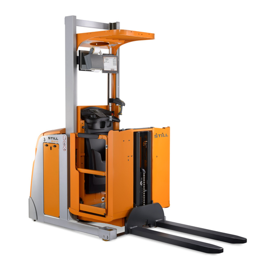
- Page 1 Original instructions High-level order picker EK-X10 2101 24 V EK-X 2131 24 V EK-X 2133 48 V EK-X 2137 24 V EK-X 2138 48 V PXV 2142 24 V PXV 2144 48 V PXV 2146 24 V PXV 2147 48 V 2101 2131 2133 2137 2138 2142 2144 2146 2147 5213 804 2501 EN - 02/2023 - ...
-
Page 3: Table Of Contents
Table of contents Foreword General ............ 2 Safety instructions . - Page 4 Table of contents Directives and guidelines.......... 22 Driver's licence.
- Page 5 Table of contents Charging socketLithium-ion battery ......... 62 Battery replacement .
- Page 6 Table of contents Special versions, special equipment ........ 107 Maintenance schedule, 1000 hours.
- Page 7 Table of contents Protective roof cover .......... 146 Mirror and lighting module .
-
Page 9: Foreword
Foreword... -
Page 10: General
Foreword General General Our industrial trucks comply with the applica- themselves with, understand and adhere to ble regulations stated in the declaration of the contents of these instructions prior to com- conformity. Any other applicable country-spe- missioning. cific regulations or operating conditions for the The operational readiness, performance and use of industrial trucks must also be observed. -
Page 11: Safety Instructions
Foreword Safety instructions Safety instructions Explanations of the terms used in this manual: DANGER There is the risk of fatality to the operator. The procedures indicated should be complied with in full in order to avoid this danger. WARNING There is a hazard that could cause major damage to property or to the health of the operator. -
Page 12: Declaration Reflecting The Declaration Of Conformity
Declaration reflecting the declaration of conformity Declaration reflecting the declaration of conformity Declaration Declaration STILL GmbH Berzeliusstraße 10 22113 Hamburg Germany We declare that the specified machine conforms to the most recent valid version of the directives specified below: ... -
Page 13: Nameplate
Foreword Nameplate Nameplate Nameplate the EFTA States and Switzerland; UKCA Manufacturer mark for the United Kingdom market; EAC Model/serial number/year of manufacture mark for the Eurasian Economic Union mar- Tare weight Max. battery weight/min. battery weight Rated drive power Ballast weight Battery voltage Placeholder for "data matrix code"... -
Page 14: Operator, Form Of Address
Internet address and QR code The information can be accessed at any time by pasting the address https://m.still.de/vdma in a web browser or by scanning the QR code. Operator, Form of address Our products are suitable for use by male or use only the masculine form of address, here- female operators. -
Page 15: Dimensions Of The Operator's Compartment
Foreword Dimensions of the operator's compartment Dimensions of the operator's compartment The dimensions of the operator's compart- If these industrial trucks are operated by per- ment on our industrial trucks are designed in sons who do not meet the criteria specified in accordance with standard DIN EN ISO 3411 EN ISO 3411, the following effects must be and are accordingly constructed for both fe-... -
Page 16: Accessories Accompanying The Product
Foreword Accessories accompanying the product Accessories accompanying the product Each truck is supplied with a box of accesso- a suitable position in the control compartment ries upon delivery from the factory. near the magnetic brake. The contents differ depending on the truck This box also contains the documentation to type and the order. -
Page 17: Storage And Transfer
Foreword Storage and transfer Storage and transfer These operating and maintenance instruc- When the product is sold on, all documenta- ● ● tions must be stored so that the operator tion must be handed over too. has access to them at all times. Documentation can be reordered. - Page 18 Foreword Storage and transfer 10 5214 804 2500 EN - 02/2023 - 03...
-
Page 19: Safety
Safety... -
Page 20: Working Safely
Safety Working safely Working safely The industrial truck must be operated exclu- access information, e.g. in the case of elec- ● sively from the driver's compartment. tronic access control. If industrial trucks are equipped for pedes- Observe the instructions in the section ●... -
Page 21: Climbing Into Or Out Of The Truck
Safety Climbing into or out of the truck Operational safety takes priority over working speed! Climbing into or out of the truck Additional hazards for industrial trucks DANGER without a raisable driver's compartment Risk of accident. In principle, the following applies (man-down) to all industrial trucks: If the operator jumps off the industrial truck even though the industrial truck has... -
Page 22: Medical Equipment, Implants
Safety Medical equipment, implants Tests have indicated that the amplitude of the erating company at the actual place of use in hand and arm vibrations on the steering wheel accordance with Directive 2002/44/EC, in or- or on the operating devices in the truck is less der to consider all additional influences, such than 2.5 m/s . -
Page 23: Special Safety Information About Load Pick Up
Safety Special safety information about load pick up Special safety information about load pick up Recognising danger is half the battle! Before every load pick up, make sure that ● the load to be picked up does not exceed the load capacity of the truck (refer to the load capacity diagram) or the maximum permissible dimensions as specified on the... -
Page 24: Safe Handling Of Consumables
Safety Safe handling of consumables Safe handling of consuma- bles The following consumables are used in this truck: Gearbox oil ● Hydraulic oil ● Battery acid ● Comprehensive safety regulations apply when handling these materials. The most important points are: For gearbox oil and hydraulic oil DANGER Danger to life or risk of injury caused by the escape... -
Page 25: Safe Handling Of The Battery Cable
Safety Safe handling of the battery cable For battery acid DANGER Risk of explosion – An explosive gas mixture can form when charg- ing batteries. This can remain in the atmosphere for a lengthy period of time even after the charg- ing process has finished. -
Page 26: Risk Assessment
Safety Risk assessment Risk assessment Within the scope of validity of the CE guide- complete the risk assessment. The operating lines, the operating company must create op- instructions are intended to warn against the erating procedures on the basis of a risk identified dangers and provide information on assessment. -
Page 27: Residual Risks When Using Order Pickers
Safety Residual risks when using order pickers Residual risks when using order pickers to the operator from static building or racking DANGER parts. Risk of accident The risk exists in trucks: – During driving, the operator must make sure that all body parts are located within the truck contour Without barriers and a cab rail ●... -
Page 28: Intended Use
Safety Intended use Intended use These industrial trucks are intended for use in order picking applications, i.e. for collecting parts that are stored in racking systems, for example. This industrial truck is therefore des- ignated as a vertical order picker. The forks must be equipped with suitable load-carrying equipment in order to set down the parts picked for the order. -
Page 29: Regular Testing
Safety Regular testing Regular testing This industrial truck must be tested in accord- If defects are found, they must be rectified be- ance with our specifications by a specialist fore the truck is next commissioned. If serious (expert) at least once per year or after any repairs are required (e.g. -
Page 30: Narrow-Aisle Trucks
Safety Narrow-aisle trucks as this reduces the braking performance of the Improper cleaning, e.g. using regreasing industrial truck. cleaning materials, can have a negative effect on the floor properties, especially the friction Objects lying around must be removed. values. In order to ensure occupational safety, we recommend that a specialist company is It is the responsibility of the operator to as- commissioned to clean the area of application. -
Page 31: Alterations To Industrial Trucks
Safety Alterations to industrial trucks Alterations to industrial trucks Make and approve corresponding altera- Operating companies may only make altera- ● tions to the signs stating the load capacity, tions or arrange for alterations to be made to information signs and adhesive labels as self-propelled industrial trucks if the industrial well as in operating manuals and workshop truck manufacturer has withdrawn from busi-... - Page 32 Safety Conversion, retrofitting, rebuilding 24 5214 804 2500 EN - 02/2023 - 03...
-
Page 33: Overview
Overview... -
Page 34: Components Of The Industrial Truck
Overview Components of the industrial truck Components of the industrial truck (1) Lift mast (2) Battery compartment (3) Driver's compartment (4) Fork arms (5) Load castors (6) Battery compartment door*, followed by the battery and the battery lock (7) Removable collision protection (8) Removable hood to the control compart- ment (9) Removable hood to the battery compart-... -
Page 35: Standard Design Of Labelling
Overview Standard design of labelling Standard design of labelling Nameplate Storage space for the abseil system Load capacity diagram Risk of crushing feet a. Do not transport people on the load or on Foot switch the load support. Storage space for product documentation b. - Page 36 Overview Standard design of labelling NOTE Additional, order-dependent information signs are explained in the section Labelling for spe- cial equipment . 28 5214 804 2500 EN - 02/2023 - 03...
-
Page 37: Labelling For Special Equipment
Overview Labelling for special equipment Labelling for special equipment Truck with customised software. Only the Lubricants suitable for cold store applica- customer's special version and not the tions must be used (see lubricants for cold standard software may be installed in the store trucks). -
Page 38: Truck Description
Overview Truck description Truck description You can find information about how to operate ered. All movements (driving, lifting/lowering the individual functions in the corresponding main lift [cab lift], lifting/lowering auxiliary lift) chapters. are infinitely adjustable. Operating errors can be prevented to a large General information extent by means of safety circuits. - Page 39 Overview Safety equipment Barrier WARNING Danger of crushing There is a risk of hands being crushed if the barrier is grasped at other points while being opened. When opening and closing the barrier, only grasp the handles to operate the barrier. Up to a cab floor lift height of 1.2 m, the cab barri- ers may be left open when the truck is being driven.
-
Page 40: Operating Panel, Variants
Overview Operating panel, variants Operating panel, variants The operating panel is fitted on the mast side are used. as standard for order pickers. As an option, Operation and indicators are described in sep- the operating panel can be mounted on the arate sections. -
Page 41: Operating Panel - Standard Display - Lcd Display
Overview Operating panel - Standard display - LCD display Operating panel - Standard display - LCD display Emergency off switch Enable button, e.g. for releasing the brake in Horn button an automatic braking system or as bridging Handhold and sensor surface for two-hand for the intermediate lift cut-out* operation Auxiliary lift selection button... -
Page 42: Standard Display
Overview Standard display Control rocker for cab lift or auxiliary lift lift- ing/lowering function *Option Standard display Display for operating hours and battery re- not assigned sidual charge. When the truck is switched not assigned on, the operating hours are displayed for 1 s not assigned and then the residual charge of the battery is Steering angle, actual value... -
Page 43: Displays
Overview Displays Displays Operating hours The operating hours are displayed for a few seconds directly after switching on the truck. The display then changes to the battery resid- ual charge. The operating hours are counted according to the setting in the truck control unit and are displayed in 1/10 hours (6-minute cycle). -
Page 44: Lcd Display
Overview LCD display LCD display Input of the number 0 or switch to weight Input of the number 7 or switch to drive pro- indicator in kg* gramme 3* Input of the number 1 or switch to drive pro- Input of the number 8 or switch to lift height gramme 1* display in mm Input of the number 2 or switch to speed... -
Page 45: Displays, Information
Overview Displays, information Indicators Enable button required Two-hand operation required* Maintenance interval expired* Pin code input via keypad required* Creep speed active* Display for operating hours, speed*, lift Steering angle display* height*, load weight*, error messages Battery discharge indicator Barrier open* Inductive forced steering in automatic mode Operating status of the personal protection Operating status of inductive forced steering... - Page 46 Overview Displays, information - Left hand operation does not come before selecting lifting or lowering. - Wiring defective. Remedy: - Reset by switching the truck off then on again. - Release the operating devices and select in correct sequence. Info 15 ...
-
Page 47: Operating Panel - Lcd Display With Keypad
Overview Operating panel - LCD display with keypad Operating panel - LCD display with keypad Handhold and sensor surface for two-hand Auxiliary lift selection button operation LCD display or cover (depending on order) Operating lever for forward/backward driving Horn button Steering knob and sensor surface for two- Emergency off switch hand operation... -
Page 48: Lcd Display With Keypad
Overview LCD display with keypad LCD display with keypad Operation 1 - 5 and 11 - 15 Selection keys for favourites Auxiliary lift selection button Selection of a menu display Enable button, e.g. for releasing the brake in Selection within a menu an automatic braking system or as bridging Go back one step in the menu or cancel a for the intermediate lift cut-out*... -
Page 49: Lcd Display With Keypad
Overview LCD display with keypad LCD display with keypad Indicators *1 only with "weight measurement" option. *2 only with "IZF" option Operating status of steering Residual capacity of traction battery Lift height (top edge of load fork) Operating hours Weight of the supported load *1 Time Operating status of guidance *2 Current driving speed... - Page 50 Overview LCD display - Programming - Menu structure Function Operating statuses and information relevant to operation are shown on the display. Using the display, it may be possible to switch functions on and off or to switch between defined sta- tuses.
- Page 51 Overview LCD display - Programming - Menu structure Menu structure The ten membrane keys can be freely config- ured to display your favourite functions on the main page. As soon as the button (7) is actu- ated, the menu bar (1) opens. From this point the structure is always the same.
- Page 52 Overview LCD display - Programming - Menu structure Top status bar The status bar at the top of the display is divi- ded into three fields: Left field (1) ● Centre field (2) ● Right field (3) ● The status bar can display the following infor- mation: Display Information...
- Page 53 Overview LCD display - Programming - Menu structure Type of guidance and steering angle (3) ● Driving speed (4) ● This part of the display cannot be parametr- ised. Operation The display is operated using 15 membrane keys. The function of buttons (2) to (4) is fixed. Button (5) has two functions.
- Page 54 Overview LCD display - Programming - Menu structure If the button is pressed and held when a drive order is active, the drive order is deleted.* The right-hand menu bar with the available data regarding height preselection opens. If the symbol is greyed out, the industrial truck is equipped with the navigation option and the key switch for nav-...
- Page 55 Overview LCD display - Programming - Menu structure Changing the language The texts are available in 25 languages. The language can be set using a fixed key combi- nation. This combination is the same for all languages. Procedure – Push button (7). The menu in area (1) opens.
- Page 56 Overview LCD display - Programming - Menu structure – Use buttons (1) to (10) to select the position for the favourite function. – Select the desired function in the list using buttons (6) to (10). NOTE On some buttons there is a sub-menu with additional options.
-
Page 57: Operating Instructions
Overview Operating instructions Brightness setting The brightness is automatically adjusted by a brightness sensor (1) below the display. NOTE For the automatic brightness feature to func- tion correctly, the sensor must not be covered or contaminated. Operating instructions The controller assists the operator in operating The messages in plain text provide direct in- the industrial truck effectively. -
Page 58: View Into The Control Compartment
Overview View into the control compartment View into the control compart- ment Narrow chassis Control current fuses Steering gears and gearbox Programming interface Removable collision protection Main current fuse for steering Hydraulic oil tank Main current fuse for driving and pump Filling opening for hydraulic oil Unassigned fuse holder Pump motor... - Page 59 Overview View into the control compartment Wide chassis Control current fuses Steering gears and gearbox Programming interface Collision protection Main current fuse for steering Hydraulic oil tank Main current fuse for driving and pump Hydraulic oil filter Truck control unit Filling opening for hydraulic oil Horn Emergency lowering valve...
- Page 60 Overview View into the control compartment 52 5214 804 2500 EN - 02/2023 - 03...
-
Page 61: Operation
Operation... -
Page 62: General Commissioning
Operation General commissioning General commissioning Initial commissioning NOTE Observe the section entitled Safe handling of consumables . Prior to initial commissioning, make sure that the entire industrial truck is properly assem- bled. All electrical and hydraulic connections must be checked. Mechanical connections that were removed for transportation must be reconnected with particular care. - Page 63 Operation General commissioning Hooking on NOTE We always recommend the use of textile straps so as to protect the paintwork of your truck. Shims may be required to protect the harnesses from sharp edges. The lifting points for the chassis are located on the right and left in the area of the load wheels, as well as in the chassis area next to the drive unit.
-
Page 64: Weights Of The Units
Operation General commissioning Mast bracing Mast bracings may be required depending on the configuration of the industrial truck. Once the mast bracings have been installed, they must be adjusted according to factory specifications and tightened to the specified torques. The mounting locations are marked with la- bels. - Page 65 Operation General commissioning specify the correct weight for each unit and for Overall height of the Weight each variant. The information and table for the double lift mast lift masts below provide rough guidelines. For 3400 mm 1172 kg safety reasons, always add a generous mar- 3900 mm 1341 kg gin when rounding up the determined value.
-
Page 66: Support Screws
Operation General commissioning Support screws CAUTION Risk of accident as a result of the truck tipping over! Support screws may only be adjusted by authorised service personnel. The basic position of the support screws must correspond to the information on the load ca- pacity diagram. -
Page 67: Traction Battery
Operation General commissioning Battery acid is toxic. Do not inhale vapours. When heavy weights are being handled, ● ● there is a risk of limbs or bodies becoming Battery acid is corrosive. Avoid skin contact. ● trapped or crushed. To avoid this, operate Rinse off spilled or splashed battery acid ●... - Page 68 Operation General commissioning DANGER Risk of accident due to the industrial truck tipping over A battery that is too light seriously reduces the stabil- ity of the truck. As a result, there may be a risk of the truck tipping over. The battery must comply with the specifications on the nameplate of the industrial truck regarding volt- age and weight.
- Page 69 Operation General commissioning Commissioning If your industrial truck is equipped with a Euro battery male connector, make sure that the voltage index pin is in the correct position. The set voltage can be read through a display window (1). WARNING Risk of accident Risk of injury from crushing zone and shearing zone...
-
Page 70: Charging Socketlithium-Ion Battery
Operation General commissioning Charging socket Lithium-ion battery Industrial trucks with a lithium-ion battery are equipped with an externally accessible socket for the charging cable. To plug in the charging cable, the spring-loaded flap is pushed inward with the plug and the plug is inserted. NOTE When the charging plug is inserted, the plug flap is pressed open. -
Page 71: Battery Replacement
Operation General commissioning Battery replacement Battery replacement using a truck As standard, the battery rests in a recess in- tended for this purpose in the chassis (1). The battery can be replaced using a truck. In order to do this, lift the battery sideways out of the recess using a truck with sufficient load-bear- ing capacity and suitable lifting accessories. - Page 72 Operation General commissioning Removing the battery compartment cov- Depending on the design of the industrial truck, the battery compartment cover can ei- ther be removed manually or folded via a spe- cial hinge. This makes the battery accessible from above, so that you can access the bat- tery male connector or perform battery mainte- nance.
- Page 73 Operation General commissioning Battery compartment door* The side openings of the battery compartment can be closed with battery compartment doors if required. Two swing bolts hold the doors in their positions. To remove the battery compartment doors, move the two rotary handles into the open po- sition by rotating them 90°.
-
Page 74: Daily Commissioning
Operation Daily commissioning Daily commissioning Checklist before starting work Checking the access control WARNING It must be possible to remove the key and it ● If any defects that could influence operational and must not be possible to operate the industri- road safety are determined during the daily pre-shift al truck when the key is in the O position or check, measures must be taken immediately to en-... - Page 75 Operation Daily commissioning If lighting devices* are fitted, check that they *Option ● are working correctly. Check that the battery lock is in perfect con- ● dition and functions correctly. 5214 804 2500 EN - 02/2023 - 03 67...
-
Page 76: Driver's Compartment
Operation Driver's compartment Driver's compartment Climbing into or out of the truck Additional hazards for industrial trucks DANGER without a raisable driver's compartment Risk of accident. In principle, the following applies (man-down) to all industrial trucks: If the operator jumps off the industrial truck even though the industrial truck has not yet come to a standstill, there is a risk that the WARNING... -
Page 77: Barriers
Operation Driver's compartment Barriers Depending on the version, the industrial truck either has no barriers or is equipped with one of the two versions of barriers shown. WARNING Risk of crushing If the barrier is touched at any point other than the points indicated while it is being opened, there is a risk that hands may be crushed. -
Page 78: Operating Devices
Operation Operating devices Operating devices Brake system Integrated foot switch The foot switch (1) is installed in the cab floor. This component must be actuated in order to release the electromagnetic spring loaded brake, and at the same time keeps the driver in the centre of the cab. -
Page 79: Steering System
Operation Operating devices Reversing brake Direct switchover from one travel direction to the other (2) activates the reversing brake. This carries out electrically controlled braking followed by acceleration in the opposite direc- tion. This braking mode can be finely metered by the deflection of the driving lever. - Page 80 Operation Operating devices Steering knob The steering knob has a right and a left stop. The rotation range of the steering knob is ap- proximately 135° to each side. The steering thereby moves a maximum of around 95° to each side.
-
Page 81: Switching On The Controller
Operation Operating devices Switching on the controller – Remove the battery compartment cover and insert the battery male connector (1) For industrial trucks with an open platform: – Step onto the platform. For industrial trucks with a cab: – Climb into the cab and close the barriers. Only hold the barriers by the marked areas of the handle (2). - Page 82 Operation Operating devices Unlocking the emergency off switch – Release the emergency off switch (3) by turning it. – Switch on the key switch (4). If the industrial truck is in an error-free state, the corresponding displays light up in the dis- play unit.
-
Page 83: Driving
Operation Driving Driving Types of guidance The industrial trucks can be designed for: The industrial trucks can be guided mechani- cally when travelling within aisles. To achieve Driving without guidance ● this, a rail system is installed on the floor Driving with one-sided guidance (side guide ●... -
Page 84: Driving Without Automatic Guidance
Operation Driving Driving without automatic guid- ance WARNING Risk of accident Observe the checklist before starting work and all safety instructions. Initial driving exercises In order to become familiarised with the driv- ing and braking characteristics of this indus- trial truck, initial driving exercises can be per- formed in a flat, obstacle-free area of the warehouse. - Page 85 Operation Driving Operating lever for driving The drive direction and speed are selected through decisive movement of the driving op- erating lever (2). When the drive switch is moved in the opposite direction, you can change directly from one drive direction to another.
- Page 86 Operation Driving Steering The left hand controls the steering knob (3) and the steering wheel*(4) and thus deter- mines the course of the truck. The maximum angle of rotation of the steered wheel is ap- proximately 95° to each side. This enables the industrial truck to be turned on the spot.
-
Page 87: Driving With Guidance
Operation Driving Emergency off switch Pressing the emergency off switch (5) acti- vates mechanical braking and brakes the in- dustrial truck to a standstill in the shortest dis- tance possible. WARNING Risk of accident Never turn the key switch to the "off" position during travel, as this will cause all safety monitoring equip- ment to be switched off. - Page 88 Operation Driving The pivoting wheel must be brought into the ● straight-ahead position. The truck can now only be driven with two- ● hand operation. To do so, touch the steer- ing knob or the steering wheel with the left hand.
- Page 89 Operation Driving Changing aisles If the industrial truck is to be driven out of one aisle and into another, note the following: Before exiting an aisle, put the steering into ● the straight-ahead position. The full length of the industrial truck must ●...
-
Page 90: Load Pick Up
Operation Load pick up Load pick up Picking up and setting down loads Picking up a load NOTE On this truck, a load is understood to be when loading equipment is picked up on the fork to collect items for order picking, as described in the section entitled Intended use . -
Page 91: Load Capacity Diagram
Operation Load pick up Load capacity diagram A load capacity diagram is mounted in the driver's cab. The load capacity diagram and the load capacity restrictions indicated for cer- tain application conditions must be observed. If they are not observed, the stability of the industrial truck will be impaired. -
Page 92: Support Screws
Operation Load pick up Support screws The support screws for this type of industrial truck can be set to a ground clearance of be- tween 15 mm and 39 mm. The setting dimen- sions for this special industrial truck can be found in the load capacity diagram. -
Page 93: Lifting Accessories
Operation Load pick up The operating company must provide the op- tor to perform order picking of packages with- erator with suitable tools to enable the opera- out danger. Lifting accessories The wide range of applications for these order pickers requires an entire range of variants of driver’s cabs and lifting accessories. -
Page 94: Load Pick Up Without Guidance
Operation Load pick up Load pick up without guidance Order pickers are mainly intended for collect- ing or distributing goods in a container or on a pallet. When transporting loads, the auxiliary lift must always be lowered. DANGER Risk of tipping in the load direction During picking work, goods for transport, and there- fore weight, accumulates on the load support. -
Page 95: Load Pick Up With Guidance
Operation Load pick up Auxiliary lift, load-side operation These trucks can optionally be equipped with load-side operation for the auxiliary lift. Auxiliary lift preselection lifting lowering not assigned Load pick up with guidance Order pickers are mainly intended for collect- ing or distributing goods in a container or on a pallet. - Page 96 Operation Load pick up Auxiliary lift Before actuating the control rocker at (1) or (2), press the button (3). Auxiliary lift selection button Auxiliary lift, load-side operation These trucks can optionally be equipped with load-side operation for the auxiliary lift. Auxiliary lift preselection lifting lowering...
-
Page 97: Emergency Operation
Operation Emergency operation Emergency operation Emergency operation If part of or the entire industrial truck control system fails, the industrial truck can be moved out of the working area in emergency opera- tion. Removing the hood To gain access to the control compartment, the hood must be removed. - Page 98 M4 nuts and M4 washers (2) into the bores provided and tighten. Towing, steering functioning If the industrial truck's steering is still working and the brake is released, the industrial truck can be towed either with a rope or with the tow bar, as long as suitable lifting points can be found for the tow bar.
- Page 99 Operation Emergency operation design, the heavy-duty rollers must be placed underneath the drive wheel or underneath the chassis. As the drive wheel does not come into contact with the ground when using this towing method, the brakes can also no longer operate.
- Page 100 Operation Emergency operation Emergency steering WARNING Risk of injury Before the steering is activated manually as descri- bed below, switch off the key switch and disconnect the battery male connector. Secure the jacked-up industrial truck using support blocks or jacks. CAUTION Risk of damage to property Under no circumstances must the assembly lever be...
-
Page 101: Emergency Lowering Valve
Operation Emergency operation Emergency lowering valve NOTE For this industrial truck type, a hand-operated valve is installed in trucks with a possible cab lift height of 3 m and above. This valve can be used to lower the lifted cab by a second person on the ground. - Page 102 Operation Emergency operation WARNING Risk of injury The attachment and load must have enough space from the racking on all sides. Otherwise, safe lower- ing of the cab cannot be guaranteed. If the operator falls unconscious, make sure that all parts of the body are completely inside the driver's cab and that there is no risk of injury for the operator during the lowering procedure.
- Page 103 Operation Emergency operation Restarting after emergency lowering WARNING Risk of accident If the emergency lowering function was required due to a technical defect, the industrial truck may be put back into operation only once the cause of the defect has been rectified by a specialist. If, as described above, a mechanical jam of the lift mast is suspected, the abseil system must not be used.
-
Page 104: Emergency Abseil System
Operation Emergency operation Emergency abseil system Exiting the raised driver's compartment in the event of an emergency NOTE An emergency abseil system is only required if the driver's compartment can be raised higher than 3000 mm above the ground. NOTE Two versions are available. - Page 105 Operation Emergency operation DANGER Risk of falling – Before using the very narrow-aisle truck, the oper- ator must be instructed in using the abseil system by a technical expert. – The operating instructions located in the rucksack must be read and followed. –...
- Page 106 Operation Emergency operation The upper end is attached to the eyelet provi- ded in the overhead guard via a carabiner. The rucksack itself is sealed using a plastic seal. The original system must not be used for prac- tice, because this causes a certain amount of wear and the seal no longer serves as a monitoring element.
- Page 107 Operation Emergency operation system for the maximum permissible service life (replacement state of wear). Once the last numbered seal has been used, the entire system must be replaced. Two-person cab Industrial trucks that feature a cab that permits two operators must also be equipped with two abseil systems.
-
Page 108: Parking, Decommissioning
Operation Parking, decommissioning Parking, decommissioning Parking and leaving the industrial truck operating the access control. Where possible, NOTE the industrial truck should be parked at the start of an aisle or in a loading bay. If park- It is the driver's duty to remove the switch ing spaces are provided, park the industrial key when he leaves the industrial truck, thus truck in a parking space. -
Page 109: Regular Care And Maintenance
Regular care and maintenance... -
Page 110: Securing The Load Carrier
Regular care and maintenance Securing the load carrier Securing the load carrier WARNING Danger for acidents Before performing any work on the hydraulic system, depressurize by lowering the load carriage to the floor. Before permitting any person into the area below the raised cab, a further mechanical safeguard such as a belt of sufficient loadbearing capacity slung around the mast cross-beams must be in position. -
Page 111: General Information About Fuses
Regular care and maintenance General information about fuses General information about fuses If a fuse needs to be replaced: Disconnect the system by pulling out the ● battery male connector Only use fuses that are identical in size and ●... - Page 112 Regular care and maintenance Fuses Wide chassis (1) Control current fuses 7.5 A Battery voltage 7.5 A Battery voltage 10 A Battery voltage 10 A 24 V 10 A 24 V 5 A 24 V 5 A 24 V 5 A 24 V 5 A 24 V (2) Main current fuses 355 A or 500 A Main current 35 A Steering system...
-
Page 113: Regular Care And Maintenance
Regular care and maintenance Regular care and maintenance Regular care and mainte- nance NOTE The regular care and maintenance of the ● industrial truck will ensure that the truck is ready for operation and will maintain its val- WARNING Risk of injury and damage to property –... - Page 114 Regular care and maintenance Regular care and maintenance Maintenance In contrast, maintenance work must be per- formed only by appropriately trained person- nel. Special tools and the current service soft- ware are required. Therefore, these activities are described only briefly in the maintenance schedule.
-
Page 115: Special Versions, Special Equipment
Regular care and maintenance Special versions, special equipment Replacement interval for lifting chains CAUTION Risk of accident The main lift chains and the auxiliary lift chain must be replaced when the wear limit is reached or if im- permissible damage is present. The technical condi- tion of the chains from a safety perspective must be assessed by a competent person using the manu- facturer's documentation. -
Page 116: Maintenance Schedule, 1000 Hours
Regular care and maintenance Maintenance schedule, 1000 hours Maintenance schedule, 1000 hours At operating hours Carried 1000 h 2000 h 3000 h 4000 h 5000 h 6000 h 7000 h 8000 h 9000 h 10000 h ... - Page 117 Regular care and maintenance Maintenance schedule, 1000 hours At operating hours Carried 1000 h 2000 h 3000 h 4000 h 5000 h 6000 h 7000 h 8000 h 9000 h 10000 h ...
- Page 118 Regular care and maintenance Maintenance schedule, 1000 hours At operating hours Carried 1000 h 2000 h 3000 h 4000 h 5000 h 6000 h 7000 h 8000 h 9000 h 10000 h ...
- Page 119 Regular care and maintenance Maintenance schedule, 1000 hours At operating hours Carried 1000 h 2000 h 3000 h 4000 h 5000 h 6000 h 7000 h 8000 h 9000 h 10000 h ...
- Page 120 Regular care and maintenance Maintenance schedule, 1000 hours At operating hours Carried 1000 h 2000 h 3000 h 4000 h 5000 h 6000 h 7000 h 8000 h 9000 h 10000 h ...
-
Page 121: 2000-Hour Maintenance Schedule
Regular care and maintenance 2000-hour maintenance schedule 2000-hour maintenance schedule Carried At operating hours 2000 h 4000 h 6000 h 8000 h 10000 h Gearbox Gearbox: perform an oil change (every 4000 hrs). ... - Page 122 Regular care and maintenance Lubricants specifications, refer to the service documenta- tion (workshop manual). Hydraulic oil HLP46 DIN 51524/T2 ● Mat. no. 7327 400 112 ● CAUTION Risk of damage to property – Observe the min/max markings on the hydraulic tank. After the hydraulic oil has been topped up or changed, the oil level must be between the min marking and the max marking.
- Page 123 Regular care and maintenance Lubricants Cleaning heavily contaminated load chains is a maintenance task and must only be carried out by appropriately trained specialist person- nel (authorised service). High-performance chain spray ● Shaft-hub connection Depending on the type of gearbox used (con- figuration of the industrial truck), it may be necessary to replace the lubricant in the shaft- hub connection between the gearbox and the...
-
Page 124: Battery Maintenance
Regular care and maintenance Battery maintenance Battery maintenance instructions from the respective manufacturer DANGER must be observed. Incorrect handling or incorrect use of batteries and chargers can cause serious damage. This can also Lithium-ion batteries lead to serious hazards for the operator. For each type of battery, the instructions provided by To ensure safe operation, industrial trucks that the battery manufacturer regarding proper use, care... - Page 125 Technical data...
-
Page 126: Technical Data
Technical data Technical data Technical data The technical data for this truck depends on the order. You will therefore receive a data- sheet specially prepared for your truck when it is delivered. Please use this accompanying datasheet to find all the technical data. Sound level, driver’s ear 61dB(A) Eco-design requirements for electric motors and variable... -
Page 127: Options
Options... -
Page 128: Additional Documentation
Options Additional documentation Additional documentation On-board charging system The options that can be ordered according to ● the price list are described below. Some op- Cold store version ● tions are self-explanatory and can be operated etc. ● intuitively and safely without a description. Industrial trucks in customised special ver- Other options, on the other hand, require ex- sions (CO = customer option) will be supplied... -
Page 129: Intermediate Lift Cut-Out
Options Intermediate lift cut-out Intermediate lift cut-out Lifting operation is stopped at a previously de- termined lift height. The ring around the ena- ble button (1) lights up. This cut-out can be overridden once the enable button has been pressed. - Page 130 Options Electronic access control is ready for operation. If the PIN code is not entered correctly, it must be entered again. Defining the PIN code Changing the PIN code The PIN code can be changed so that each industrial truck has an individual access code. To do this, an authorised person, e.g.
-
Page 131: Inductive Guidance Izfoperating Panel Variants
Options Inductive guidance IZFOperating panel variants Inductive guidance IZF Operating panel variants NOTE This industrial truck can be optionally equip- ped with various operating panels and dis- plays. As a result, operation and displays vary. Refer to the applicable sections for the appro- priate information. -
Page 132: Inductive Guidance Izf
Options Inductive guidance IZF Inductive guidance IZF System description General If your industrial truck is guided using induc- tive guidance, the shift button (1) must be pressed before the truck is guided onto the induction track and before leaving the track. This switch in the operating panel is used to switch from manual steering to automatic steering. - Page 133 Options Inductive guidance IZF – When the controller detects the induction track via the first antenna, the controller switches to automatic mode. – An acoustic signal sounds. – The two symbols (6) are lit continuously. – Continue. The industrial truck is driven au- tomatically along the centre of the wire groove.
- Page 134 Options Inductive guidance IZF for example an error, the driving speed is limi- ted or driving is switched off completely. Leaving the induction track – Drive the entire length of the industrial truck out of the aisle. – Turn off automatic steering by pushing the "man/auto"...
-
Page 135: Inductive Guidance Izf - Lcd Display With Keypad
Options Inductive guidance IZF - LCD display with keypad Inductive guidance IZF - LCD display with keypad Guidance procedure – When the guidance procedure is complete (antenna distance 15...0 mm), the coloured ring changes from grey to green. – The truck can now be driven at the permis- sible speed within the racking. -
Page 136: Aisle Entry Assistant
Options Aisle entry assistant Aisle entry assistant General Inductive guidance (IZF). This means that the truck is aligned precisely so that it can be driv- The aisle entry assistant can be used to make en into the guide rails. it easier to drive into an aisle when using Electrical aisle detection only occurs when the mechanical guidance. -
Page 137: Automatic Braking Systems
Options Automatic braking systems Automatic braking systems Automatic braking systems ensure operational safety. They make it easier for the operator to pay better attention to on-site restrictions and specifications due to the work process. Auto- matic braking systems therefore also make an important contribution to increasing handling performance. - Page 138 Options Automatic braking systems distance measurement. In racking, there may be areas in which the functions of the industri- al truck need to be restricted or locked. Such areas include those in which the truck must brake or even stop for occupational safety rea- sons, e.g.
- Page 139 Options Automatic braking systems RFID technology The RFID transponders are embedded in the hall floor. They are located in approx. 8 mm holes slightly outside the centre of the aisle at different intervals. The RFID writing/reading device is mounted on the load wheel axle un- der the driver's cab or under the battery com- partment.
- Page 140 Options Automatic braking systems Reflective light switches and reflectors Reflective light switches attached to the indus- trial truck detect the reflectors in both drive di- rections while the industrial truck is in motion. The reflectors are attached to the uprights approx.
-
Page 141: Other Battery Male Connectors
Options Other battery male connectors Other battery male connec- tors Battery connectors from other manufacturers are available as an option. WARNING Risk of damage to property, risk of accident, risk of short circuit If the operator modifies the factory-supplied battery connection, this must be checked for fitness and compliance with the required specifications for the intended location of use by a qualified person before... - Page 142 Options Battery on a roller channel CAUTION Risk of accident and damage to property – Before starting work, check that the battery lock is in good working order and that it functions cor- rectly and ensure that the clamping screws are secured in place.
- Page 143 Options Battery on a roller channel Battery lock for wide chassis The battery lock is electronically monitored (1). If this monitoring function detects an error, the driving speed of the truck is limited to 1 km/h and an error message appears on the display.
- Page 144 Options Battery on a roller channel Battery lock for narrow chassis Installing the battery lock The locking plate (2) is inserted into the side openings with the clamping screws (1) open. After the clamping screws are tightened, the rubber buffers (3) press against the battery tray.
- Page 145 Options Battery on a roller channel Internal battery lock With this type of chassis, the battery is se- cured with a lock located above the battery. To lock the battery securely, push both levers downwards. 5214 804 2500 EN - 02/2023 - 03 137...
- Page 146 Options Battery on a roller channel Adjusting the clamping screws To ensure the operational safety of this indus- trial truck, the traction battery must be secure- ly fixed in place in the battery compartment by means of clamps. To achieve this, the in- dustrial truck is equipped with an adjustable battery lock.
-
Page 147: Tilt Barrier
The consequences would be a risk of accident and damage. – When the clamping has been carried out, part of the thread must still be visible at (5) and (6). Tilt barrier Description ... -
Page 148: Leaning Cushion
Options Leaning cushion NOTE If one of the two barriers is opened and then closed again, the tilting order picking barrier is locked. It is unlocked again if the foot switch is briefly actuated once and the remaining condi- tions are fulfilled for it to be unlocked. Leaning cushion ... -
Page 149: Safety Laser Scanner
Options Safety laser scanner CAUTION Risk of accident Even if a personal protection system is used, we do not permit people and very narrow aisle trucks to be in the same aisle at the same time. NOTE The makes of mobile personal protection sys- tems approved by us are not identical as re- gards functions and options. -
Page 150: Preparation For The Personal Protection System
Options Preparation for the personal protection system – Observe cleaning instructions. CAUTION – Do not adjust the scanner or cover the openings. Functional impairment – Observe the operating instructions provided by the scanner manufacturer. Preparation for the personal protection system Preparation for immediate installation Collisions cannot be avoided ●... -
Page 151: Radio Installation
Options Radio installation Radio installation Industrial trucks can be prepared in the facto- ry for the installation of a car radio (1). The preparation consists of: Console underneath the overhead guard ● with two built-in loudspeakers. Standard installation slot for the installation ●... -
Page 152: Driver's Compartment Options
Options Driver's compartment options Driver's compartment options The driver's compartment can be optionally equipped with various additional functions. This enables the functionality to be optimised for the application area in question. (1) LED headlights on the side for illuminat- ●... -
Page 153: Mounting System For Auxiliary Components
Options Mounting system for auxiliary components Mounting system for auxiliary components The driver's cab can be equipped with a system consisting of rods and support mount- ings in order to mount additional components. These can either be installed at the factory or retrofitted by the customer. -
Page 154: Protective Roof Cover
Options Protective roof cover Protective roof cover The standard overhead guard meets the cur- rent standards in terms of stability and the distance between the roof struts. However, if heavy objects that are small enough to fit through the roof struts of the overhead guard are transported in a storage area, there is a danger that if they fall from a considerable height, they may fall through the overhead... -
Page 155: Operating Panel, Load Side
Options Operating panel, load side The mirror can be moved into the required po- sition by pushing on the corresponding places. CAUTION Risk of damage to property The adjustment range is mechanically limited. Push- ing too hard on the mirror glass can cause the glass to crack. -
Page 156: Video System For Monitoring The Travel Path
Options Video system for monitoring the travel path Video system for monitoring the travel path As an option, these industrial trucks can be equipped with video cameras and monitors. The basic equipment consists of a video cam- era that is aligned in the drive direction (3) and another video camera that is aligned in the load direction (2). -
Page 157: Mms Interface
Options MMS interface MMS interface Additional components in the driver's cab require galvanically isolated power supplies. Each power supply has a separate fuse. The customer's printer or terminals can there- fore be supplied with voltage. The mounting position and number, as well as the voltage supplied, are order-specific. -
Page 158: Usb Charging Station
Options USB charging station USB charging station This charging station can be used to charge two consumers with USB charging cables at the same time. Maximum charging power per socket: 2 A. NOTE Protect against contamination and damage. When the charging station is not in use, cover the sockets with the hinged cover. - Page 159 Options Rescue Alarm an operating error, Resetting the alarm ● defective switching elements or ● The alarm is reset by actuating the foot switch health problems on the part of the ● or closing the open barrier. operator. If the alarm is not reset, the horn and the flashing light are activated five times.
-
Page 160: Special Equipment For Cold Store Application
Options Special equipment for cold store application Special equipment for cold store application Trucks for cold store application are equipped with many special attachments in order to guarantee full function in low temperatures (-30°C). Separate instructions must be ob- served for the operation of these trucks, which are not included in these operating instruc- tions. -
Page 161: Lifting Accessories
Options Lifting accessories Lifting accessories The wide range of applications for these order pickers requires an entire range of variants of driver’s cabs and lifting accessories. Customer-specific solutions are also often de- veloped. Where applicable, these special versions are described in specially prepared documenta- tion. -
Page 162: Modified Load Pick Up
Options Modified load pick up Modified load pick up There are variants of this order picker that When the picking process is completed, the have aid is handed in and exchanged for an empty one. an order-picking cage or an order-picking ●... -
Page 163: Two-Person Cab
Options Two-person cab Two-person cab Provided a driver's cab is equipped according- ly, two people may be in it at the same time during normal operation. NOTE When the industrial truck is operated by the operator and the passenger in the cab, the ergonomic conditions are impaired. - Page 164 Options Two-person cab stipulates ranges within which the operator's body weight and dimensions should lie. EN ISO 3411 specifies 114.1 kg for the maximum body weight for a large operator. CAUTION Reduction in the load capacity. Negative effect on stability. If the actual body weight of the operator and passen- ger combined exceeds 114.1 kg, the maximum load weight must be reduced by the difference compared...
- Page 165 Options Two-person cab Handholds Two handholds (3) are provided so that the passenger is able to hold on with both hands at all times, thus keeping the passenger's body in a safe position. For monitoring purpo- ses, the passenger must always actuate both buttons (4).
- Page 166 Options Two-person cab Foot switch One or two additional foot switches (5) force the passenger to adopt a safe position. If the passenger releases one of the foot switches during travel, the industrial truck will stop im- mediately. Further equipment Depending on the lift mast design and cab dimensions, protection against accidental con- tact with the lift cylinders situated behind the...
-
Page 167: Pedestrian Mode
Options Pedestrian mode Release all switches and actuate them in the correct sequence. If this does not restore the correct function and the error message disappears, call the author- ised service centre. Pedestrian mode As an option, the industrial truck can be equip- ped with the additional "pedestrian mode"... -
Page 168: Fall Protection Device
Options Fall protection device Fall protection device If the operating procedure requires the opera- tor to open the barrier with the driver's cab raised, for example, in order to better access the stored goods, additional safety measures must be taken. An additional safety measure can be a fall protection device worn by the operator at all times and permanently attached to the overhead guard. -
Page 169: Working Platforms
Options Working platforms DANGER Risk of fatal injury due to incorrect use If an industrial truck is equipped with a fall protection device: – The operator must be trained and instructed in how to use the system before using the industrial truck. -
Page 170: Antistatic Version
Safety headlights are available in different colours. DANGER The driver of the industrial truck still has full duty of care in relation to pedestrians and other industrial trucks, regardless of whether this safety headlight is fitted to their truck. - Page 171 Options Safety Light safety headlight Residual dangers Due to the functionality and design of the sys- tem, the safety headlight cannot provide com- prehensive protection for other transport users in the racking system. The safety headlight cannot illuminate in the direction of crossing traffic.
- Page 172 Options Safety Light safety headlight Maintenance Before starting work, the driver must check whether the distance between the beam of light and the truck is correct. Clean the lens of the safety headlight if it is contaminated. Apart from these measures, the safety headlight is maintenance-free.
- Page 173 Options Safety Light safety headlight Technical data Operating voltage 12 – 100 V Power consumption 5 W Current draw 0.2 A at 24 V Service life >20,000 hours Protection class IP68 - IP69K Operating temperature -40°C - +85°C 5214 804 2500 EN - 02/2023 - 03 165...
- Page 174 Options Safety Light safety headlight 166 5214 804 2500 EN - 02/2023 - 03...
- Page 175 Index Battery compartment doors... . 65 Battery connector....50 Abseil system....26, 155 Battery discharge indicator.
- Page 176 Index Documentation, order-related..7, 8 Changing the hydraulic oil... . 113 Checking all operating devices..Documentation, product-specific.
- Page 177 Index Expert......Horn......12, 30, 50 Horn button.
- Page 178 Index Lithium-ion battery, charging socket..National regulations... . 21, 22, 23 Load-side operation....87 Navigation.
- Page 179 Index Rod system..... . . Personal protective equipment..16, 23 Picking up a load....82 Roller channel.
- Page 180 Index Switching on the controller... . . 73 VDMA......7, 23 VDMA, information booklet.
- Page 182 STILL GmbH 5213 804 2501 EN - 02/2023 - 03...
Need help?
Do you have a question about the EK-X10 2101 24 V and is the answer not in the manual?
Questions and answers