Table of Contents
Advertisement
Quick Links
- 1 Table of Contents
- 2 Handheld Controller ...................................19-20
- 3 Patient Control Panel ..................................23
- 4 Side-Rail Integrated Panel ..............................21-22
- 5 Battery Unit .......................................34
- 6 Product Symbol Definitions
- Download this manual
INSTRUCTION MANUAL
7C00023700A1
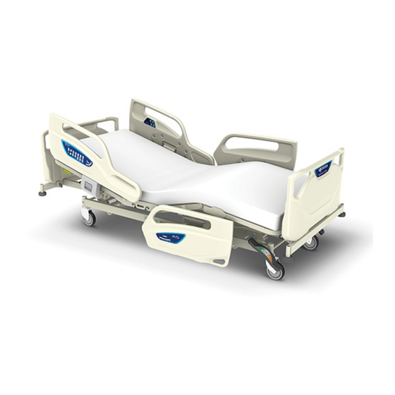
Note: In the illustration, an optional
mattress is attached.
Thank you for purchasing A5 Series Bed.
This instruction manual describes precautions and how to safely use and operate the bed.
●Before using this bed, please read this instruction manual
to fully understand the safe and proper operating procedures.
●The correct operating procedures should be explained not
only to the persons using the bed but also to caregivers.
●After reading this instruction manual,
store it where it can beeasily accessed for later reference.
●The actual product purchased may differ from detailed
descriptions given in this instruction manual due to product improvements.
●Values in the specification such as working range, dimensions,
angles and mass are subject to normal manufacturing tolerances.
Besides some exemptions, display purpose words such as
"approximately", "about" etc. are omitted.
●For any queries, please feel free to directly contact Paramount Bed or your distributor.
●Users and/or patients are requested to report information about any serious incident
related to this equipment that occurs within the EU to the manufacturer and
the regulating authority of the member country of residence.
'Serious incident' means any incident that directly or indirectly led,
might have led or might lead to any of the following:
・ the death of a patient, user or other person.
・ the temporary or permanent serious deterioration of a patient's,
user's or other person's state of health.
・ a serious public health threat.
A5 Series Bed
Advertisement
Table of Contents

Related Manuals for PARAMOUNT BED A5 Series


Summary of Contents for PARAMOUNT BED A5 Series
- Page 1 Besides some exemptions, display purpose words such as “approximately”, “about” etc. are omitted. ●For any queries, please feel free to directly contact Paramount Bed or your distributor. ●Users and/or patients are requested to report information about any serious incident related to this equipment that occurs within the EU to the manufacturer and the regulating authority of the member country of residence.
-
Page 2: Table Of Contents
CONTENTS Page .................................3 INTENDED USE / PART NAMES ....................................4-12 SAFETY PRECAUTIONS INSTALLATION ..........................................13 ASSEMBLING THE BED 1. Board ...........................................14 ....................................15 2. Mattress stopper CONNECTING TO THE POWER SUPPLY 1. Power outlets .......................................16 2. Cable storage .......................................16 OPERATION PROCEDURES 1. Operation overview ...................................17-18 2. - Page 3 Page ACCESSORIES 1. Recommended accessories table ..........................38 2. IV pole ............................................39 3. Oxygen cylinder holder(φ155mm) ..........................40 4. Oxygen cylinder holder(φ115mm) ..........................41 .........................................42 5. Lifting pole 6. Foot spacer .........................................43 ...................................43 7. Foot spacer storage ..............................44 8. Orthopedic frame attachment .............. ................44 9.
-
Page 4: Handheld Controller ...................................19-20
INTENDED USE / PART NAMES 1. Intended Use ■This bed is designed to be used for patient care in medical institutions and elderly care facilities. ※For details of the patient target groups and contra-indications, the intended users and clinical benefits, see "Specifications". 2. - Page 5 ●Precautions requiring special attention by persons using the bed are affixed as pictured in the figure. ●If the safety label is removed or defaced, replace it with a new one obtained from Paramount Bed or your distributor. On the leg section base...
- Page 6 SAFETY PRECAUTIONS ■Be careful not to allow any part of the body (especially the head or neck) to enter the gap between the side-rail, or the side-rail and the board or the mattress base (especially when raised). ●When the head or neck enters the gap, the patient and/or user might not be able to withdraw, and there is a risk of injury.
- Page 7 SAFETY PRECAUTIONS ■Be careful not to allow any part of the body to enter the gap between the bed and wall or surrounding obstacles. ●There is a risk that a part of the body may get caught, resulting in injury. ■Take care to prevent a patient from falling off the bed even when side-rails are raised.
- Page 8 SAFETY PRECAUTIONS ■Pay attention to prevent the patient from being compressed by back raising. ●Especially before birthing, if the back section base is raised excessibly, the patient might be compressed, resulting in injury. ■Use the bed in the correct orientation. ●Lying down on the bed with the feet at the head end and the head at the feet end induces an unnatural posture during bed operation (base angle) which may result in...
- Page 9 If liquids are spilt accidentally, disconnect the power plug from the power outlet and contact Paramount Bed or your distributor. ■Make sure that there is nothing in the board attachment holes or the option attachment holes when mounting the boards or the accessories.
- Page 10 SAFETY PRECAUTIONS ■Do not trip over the power cable or the handheld controller cable. ●The power plug or cables may get damaged and short circuit, resulting in electric shock or fire. ●There is a risk of injury caused by the patient falling down. ■Do not run cables (such as the power cable) of the bed or other electrical appliances under the bed.
- Page 11 ●Beds damaged in earthquakes, fires, or floods or other incidents must be inspected and repaired by Paramount bed or your distributor. Otherwise, there is a risk of electric shock or fire due to short circuit or current leakage from electrical parts, or injury due to malfunctioning caused by deformation of the bed.
- Page 12 SAFETY PRECAUTIONS ■When performing the height adjustment or inclination angle adjustment, pay attention not to hit the wall, beam, or power outlet on the wall. ●The bed or wall may be damaged or deformed. Make sure that the bed does not hit the wall, beam, or power plug during the height adjustment or inclination angle adjustment.
- Page 13 SAFETY PRECAUTIONS ■Avoid transporting over uneven floors. ●This may cause damage to the bed, or deformation or failure of the bed. If moving on uneven floor is necessary, move the bed as slow as possible. ■The handheld controller must be attached to a suitable bed. ●If it is attached to an unsuitable bed, the bed could operate unexpectedly, resulting in injury or bed failure.
- Page 14 INSTALLATION ■To avoid possible malfunctions, do not install the bed in the following ●Locations expose to direct sunlight ●Locations near heat sources such as a stove or heater ●Location which is heavily electrically charged such as near an MRI ●Location that has a high oxygen level ●Locations exposed to excessive amounts of water vapor or oil vapor ●Location that tend to be exposed to high temperatures, high humidity, low temperatures or dry conditions...
- Page 15 ASSEMBLING THE BED 1.Board ●Do not attach the board in the wrong way, or the head or neck enters the gap between the board and the side-rail, and there is a risk of injury. ●Do not leave the board detached, or a patient may fall off the bed, resulting in injury.
- Page 16 ASSEMBLING THE BED 2.Mattress stopper (CA-54380 / CA-53380 only) [Attaching the mattress stopper] ①Insert the mattress stoppers into the holes of the leg section base. ②Push the mattress stoppers inwardly. Leg section base ③Lightly push the mattress stoppers from inside to outside to make sure they are attached properly.
- Page 17 CONNECTING TO THE POWER SUPPLY 1. Power outlets ●Do not connect multiple cables to a single power outlet. if other electrical equipment is plugged into a power outlet or an extension cable and its rated capacity is exceeded, it could cause the cable or plug to overheat, resulting in fire.
- Page 18 OPERATION PROCEDURES 1. Operation over view ●When performing a position operation, check that the patient’s head, arms, feet, or other body parts have not entered the gap of the side-rails, or the space between the back section base and the frame; There is a risk of getting caught, resulting in injury. ●When performing the height adjustment or inclination angle adjustment with the side-rail lowered, do not place legs under the side-rail.
- Page 19 OPERATION PROCEDURES Trendelenburg ※4 motors type only ●The head end of the bed can be lowered. The angle can be adjusted electrically up to 12 ⁰ 0° to 12° Reverse Trendelenburg ※4 motors type only ●The head end of the bed can be raised. The angle can be adjusted electrically up to 12 ⁰...
- Page 20 OPERATION PROCEDURES 2. Handheld controller ●Do not allow the bed to be operated by a child aged 12 or under, or someone deemed incapable of comprehending the operation of the bed. If a child aged 12 or under, or someone deemed incapable of comprehending the operation (such as persons with dementia) operates the handheld controller by themselves, there is a risk of unexpected injury such as the body getting caught in the bed by accident.
- Page 21 OPERATION PROCEDURES ●Do not drop the handheld controller or pull the cable. The handheld controller may get damaged or deformed, causing it to operate incorrectly. Request repair (or replacement) of a damaged handheld controller, if necessary. ●The handheld controller must be properly set in the storage position or hung the side-rail using one hook with the buttons facing out.
- Page 22 OPERATION PROCEDURES 3. Side-rail integrated panel ●Do not allow persons other than doctors and nurses to operate the side-rail integrated panel. There is a risk of injury due to incorrect operation. ●The side-rail integrated panel includes switches for the following bed operations that are performed by doctors and nurses.
- Page 23 OPERATION PROCEDURES (8) Low height indicator ・OFF : Bed height is at the lowest position. ・Orange : Bed height is not at the lowest position. (9) Power indicator [When the battery is connected.] ・Green light : Battery is charged. The bed can be operated. ・Green flashing : Battery is not fully charged yet.
- Page 24 OPERATION PROCEDURES 4. Patient control panel ●Do not allow the bed to be operated by a child aged 12 or under, or someone deemed incapable of comprehending the operation of the bed. If a child aged 12 or under, or someone deemed incapable of comprehending the operation (such as persons with dementia) operates the side-rail integrated panel or the patient control panel by themselves, there is a risk of unexpected injury such as the body getting caught in the bed by accident.
-
Page 25: Emergency Cpr (Back-Lowering) Function
OPERATION PROCEDURES 5. Emergency CPR (back-lowering) function ●When using the emergency CPR function, make sure that the patient's and/or user's head, arms, feet or other body parts have not entered the gap between the back section base and the frame. There is a risk of getting caught, resulting in injury. -
Page 26: Adjusting The Angle Of The Leg Section Base
OPERATION PROCEDURES 6. Adjusting the angle of the leg section base ●The angle of the leg section base must be adjusted by at least two persons from both sides of the bed. If only one person attempts to adjust the angle, the person may get caught between the leg section base and main frame, resulting in injury. -
Page 27: Casters
OPERATION PROCEDURES 7. Casters ●Lock the casters at all times except when moving the bed. The bed may move when a patient gets into or out of the bed, resulting in an unexpected injury. ●Do not attempt to forcibly move the bed when the casters are locked (fixed), as doing so will cause malfunctions. - Page 28 OPERATION PROCEDURES <Individual locking system> ●Use the stopper to lock or unlock the casters. ●Stoppers are on four casters on each corners of the bed.When locking, be sure to lock all casters. ●Depressing the stopper locks the swiveling and rotation of the caster. ●Prior to locking, be sure that the caster is not out of the bed frame.
-
Page 29: Bed Side-Rails
OPERATION PROCEDURES 8. Bed side-rails ●There are a total of four side-rails, two side-rails on the left and right, respectively. ●Side-rails prevent the patient from falling off the bed. ●All the side-rails are provided with shock absorber. Side-rail position when it is raised. Side-rail position when it is lowered. - Page 30 OPERATION PROCEDURES ●Be careful not to allow any part of the body (especially the head or neck) to enter the gap between the side-rail and the mattress base or the mattress. When the head or neck enters the gap, the patient might not be able to withdraw, and there is a risk of injury.
-
Page 31: Accessory Holders
OPERATION PROCEDURES 9. Accessory holders ●Do not apply more than 3kg load to the accessory holder. This may caught damage and deformation of the accessory holder. ■Accessory holders are provided on both sides on hip section base and on both side-rails near to the footboard. -
Page 32: Restraint Belt Mounting Holes
OPERATION PROCEDURES 11. Restraint belt mounting holes ●Do not perform the bed operation such as raising the back or knee section base with a restraint belt attached to the main frame. The patient’s body may be squeezed resulting in injury or the bed may get damaged or deformed. -
Page 33: Option Attachment Holes
OPERATION PROCEDURES 13. Option attachment holes ■Option attachment holes are at the four corners of the bed. It can be installed IV pole, oxygen cylinder holder, foot spacer and orthopedic frame attachment. Option attachment hole Option attachment hole ●During tilt angle adjustment, pay attention the board and option attachment holes will become tilted at an angle. -
Page 34: Extension Frame Function
OPERATION PROCEDURES 15. Extension frame function ●When using the extension frame function, make sure to use a suitable extension mattress. There is a risk that a part of the body may get caught in a gap between the bed and the extension frame, resulting in injury. -
Page 35: Battery Unit .......................................34
12 hours, please change the battery. ○When you change the battery, please contact Paramount Bed or your distributor. ■The battery is an auxiliary power supply for operating an electrically operated bed when not connected to a power outlet. -
Page 36: X-Ray Cassette Tray ..................................35-36
OPERATION PROCEDURES 15. X-ray cassette tray ●Always disconnect the power plug for the bed from the power outlet when using X-ray apparatus. Using the X-ray apparatus without disconnecting the power plug may cause operational failure or malfunction. ●When placing a cassette to the cassette tray, be careful not to let the cassette fall from the cassette tray. - Page 37 OPERATION PROCEDURES 15. X-ray cassette tray ■Setting a Cassette. Set a cassette while the back section base is in holizontal status. ①Detach the headboard. ②Pull the lock lever to unlock it. Lock lever Lock position Unlock position Lock lever ③Hold the grip and pull the cassette tray all the way out.
-
Page 38: Mattress (Optional)
●Be sure to use a mattress of dimensions specified by Paramount Bed, described below. If an unsuitable mattress is used, patients could get caught between the mattress and side rail and get injured. -
Page 39: Accessories
CA-A3332E Orthopedic frame attachment CA-A343E Foot light MC-5037V Monitor table CF-051E Assist bar MC-5031V ●Recommend accessories may differ due to specification changes or according to product combinations. For any queries, please feel free to contact Paramount Bed or your distributor. -
Page 40: Pole
When the pipe has been adjusted to the desired length, tighten the knob bolt to fasten the pipe. ③Hang the intravenous bags or similar items on the IV pole. Hook Tighten Loosen Sliding pipe Knob bolt Option attachment hole ●For any queries, please feel free to contact Paramount Bed or your distributor. -
Page 41: Oxygen Cylinder Holder(Φ155Mm) ..........................40
②Loosen the knob bolt on the oxygen cylinder holder, and then slowly insert the oxygen cylinder into the holder from the top. ③Firmly tighten the knob bolt to fasten the oxygen cylinder. Oxygen cylinder holder Tighten Loosen Knob bolt Headboard ●For any queries, please feel free to contact Paramount Bed or your distributor. -
Page 42: Oxygen Cylinder Holder(Φ115Mm) ..........................41
③Loosen the knob bolt on the oxygen cylinder holder, and then slowly insert the oxygen cylinder into the holder from the top. ④Firmly tighten the knob bolt to fasten the oxygen cylinder. Oxygen cylinder holder Tighten Loosen Knob bolt Option attachment hole ●For any queries, please feel free to contact Paramount Bed or your distributor. -
Page 43: Lifting Pole
④Pull down the grip to make sure that the lifting pole is attached firmly. Knob bolt Outer pipe Parts of the lifting pole Grip ●For any queries, please feel free to contact Paramount Bed or your distributor. -
Page 44: Foot Spacer
Option attachment hole ●When using the extension frame function, the foot spacer cannot be used. ●For any queries, please feel free to contact Paramount Bed or your distributor. 7. Foot spacer storage ■The foot spacer storage can be used for storing the foot spacers. -
Page 45: Orthopedic Frame Attachment
Tighten Screw Option attachment hole ●For any queries, please feel free to contact Paramount Bed or your distributor. 9. Foot light ■The foot light can be used for illuminating periphery of the feet in the dark. ①Fix the footlights on both sides of the main frame of the bed with screws. -
Page 46: Monitor Table
④When using the monitor table, rotate the table upward to the horizontal position. ⑤When storing the monitor table, rotate the table downward to the vertical position. Raise Monitor table Monitor table Lower Table insertion part Option attachment hole ●For any queries, please feel free to contact Paramount Bed or your distributor. -
Page 47: Assist Bar
⑤Lightly pull the assist bar to make sure that it is attached firmly. Storing position Using position When using the assist bar When storing the assist bar ●Some models cannot add-on this option. ●For any queries, please feel free to contact Paramount Bed or your distributor. -
Page 48: Peripheral Equipment .......................................47
●The overbed table can be used in the area as shown in figure. When setting the overbed table, pay attention not to hit the caster of the bed because it may damage or deform. Note: The overbed table can be used within this range. ●For any queries, please feel free to contact Paramount Bed or your distributor. -
Page 49: Product Symbol Definitions
PRODUCT SYMBOL DEFINITIONS ■The symbols below are used for the product. Symbol Description Symbol Description ●Authorised representative ●CE mark in the european community ●Indoor use symbol ●Safe working load ●Electrical waste ●Maximum user weight ●Maximum weight ●Refer to the instruction manual (Product weight + Safe working load) ●See the instruction manual ●The medical bed for adults... - Page 50 Inspect for loose parts, the operation of moving parts on the bed, and the presence of damage regularly. When an irregularity has been noticed or when a detailed inspection is desired, contact Paramount Bed or your distributor. Operation details Inspection items Back raise operation (p.17 to...
- Page 51 REGULAR INSPECTION AND DAILY MAINTENANCE ■Lubrication (if there is abnormal noise) ●Lubrication is needed if there is abnormal noise. Please feel free to contact Paramount Bed or your distributor to be lubricated. ●The water adhesion to the bed or the mattress, or moisture may cause corrosion, abnormal noise or contamination.
- Page 52 ■Bed damaged in earthquakes, fires, floods or other incidents must be inspected and repaired by Paramount Bed or your distributor. Otherwise, there is a risk of electric shock or fire due to short circuit or current leakage from electrical parts, of injury due to malfunctioning caused by deformation of the bed.
- Page 53 ●When requesting repairs or contacting Paramount Bed or your distributor, please provide the number on the product ID label. ■Product ID label locations Product ID labels are affixed to the foot end of the main frame and on the inside of the footboard.
- Page 54 (See p.16) ●Inspect the product regularly at least once a year, even if it is during storage. Bed disposal When the A5 series bed has reached the end of its usable life, discard it according to local standards.
- Page 55 *1) CA model, IA model and MA model differ in label description, etc. For more information about specification, please feel free to contact Paramount Bed or your distributor. *2) Safe working load: Maximum load with which the bed can be operated. (The total load of user's weight and incidental items including accessories.)
- Page 56 SPECIFICATIONS Range Environmental conditions When transported or stored When in use Temperature -10 to 50℃ 5 to 40℃ Humidity 20 to 90%RH at 30℃ 20 to 90%RH at 30℃ Air pressure 700 to 1,060hPa 700 to 1,060hPa ●Essential performance Function to support the body of patient, Emergency CPR (back lower) function. ●...
- Page 57 30 cm may cause a decline in the performance of the A5 series. ● The A5 series cannot be used adjacent to another device or in a stacked state. If the A5 series must be used adjacent to another device or in a stacked state, make sure the A5 series operates appropriately at the location of use.
- Page 58 SPECIFICATIONS Guidance and Manufacturer's Declaration — Electromagnetic Immunity The A5 Series is intended for use in the following electromagnetic environment. The customer or user of the A5 Series must use it in an environment specified here. IEC 60601-1-2 Immunity test...
- Page 59 SPECIFICATIONS Guidance and Manufacturer's Declaration - Electromagnetic Immunity The A5 Series is intended for use in the following electromagnetic environment. The customer or user of the A5 Series must use it in an environment specified here. IEC 60601 Immunity test...
- Page 60 Guidance and Manufacturer's Declaration - Electromagnetic Immunity The A5 series is intended to be used in an electromagnetic environment where RF radio communication devices are used. The electromagnetic interference between the RF communication device and the A5 series can be prevented by maintaining the minimum distance between the two as recommended below in accordance with the maximum output and frequency of the communication device.
- Page 61 Mattress, casters, handheld controller, battery, the rubber parts are consumable parts. 2.Minimum stock availability period Paramount Bed keeps replacement parts (necessary to maintain bed performance) in stock for at least 8 years after the discontinuation of production. 3.Questions regarding after-sales service For any queries, please feel free to contact your distributor or to the following address.
- Page 62 NOTES...
- Page 63 NOTES...
- Page 64 2021-02...
Need help?
Do you have a question about the A5 Series and is the answer not in the manual?
Questions and answers