Table of Contents
Advertisement
Quick Links
INSTRUCTION MANUAL
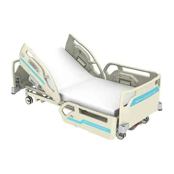
Qualitas Nx Series
Electrical Hospital Bed
7C01941700A0
* An optional mattress is attached in the illustration.
Preface
Thank you for purchasing the Qualitas Nx Series ("bed").
This instruction manual describes precautions and how to safely use and operate the bed.
To ensure safe and proper use of the bed, be sure to read this instruction manual before use.
The safe and correct operating procedures should be explained not only to the patient using the bed
for medical treatment but also to the patient's attendant.
After reading this instruction manual, store it in a place that can be easily accessed for later reference.
The actual product purchased may differ from detailed descriptions given in this instruction manual
due to product improvements.
Values in the specifications such as operation ranges, dimensions, angles and mass are subject to
normal manufacturing tolerances. Except for special cases, words such as "approximately" and
"about" are omitted in this instruction manual to improve readability.
For any queries, please feel free to directly contact Paramount Bed or your distributor.
Users and/or patients are requested to report information about any serious incident that occurs within the EU to the
regulating authority of the member country of residence.
Serious incident means any incident that directly or indirectly resulted in, may have resulted in, or may result in any
of the following.
Death of a patient, user, or other person
Serious temporary or permanent adverse effects on the health of a patient, user, or other person
Serious public health threat
PARAMOUNT BED CO., LTD.
Advertisement
Table of Contents

Related Manuals for PARAMOUNT BED Qualitas Nx Series


Summary of Contents for PARAMOUNT BED Qualitas Nx Series
- Page 1 Except for special cases, words such as “approximately” and “about” are omitted in this instruction manual to improve readability. For any queries, please feel free to directly contact Paramount Bed or your distributor. Users and/or patients are requested to report information about any serious incident that occurs within the EU to the regulating authority of the member country of residence.
-
Page 2: Table Of Contents
Table of contents Table of contents Ⅰ.BEFORE USING THE BED ..................3 1. About this bed ..........................3 Intended use and benefits ......................3 Part names ..........................3 2. Safety precautions .......................... 6 3. Product symbol definitions ......................21 ... - Page 3 Oxygen cylinder holder ......................64 Extension mattress ........................67 Foot spacer/Side-rail spacer ..................... 68 Side-rail spacer holder ......................69 Lifting pole ..........................70 Monitor table ..........................71 Traction frame ........................... 72 Bed linen rack ..........................73 ...
-
Page 4: Ⅰ.before Using The Bed
Ⅰ.BEFORE USING THE BED .BEFOR E U SIN G THE BED 1. About this bed Intended use and benefits [Intended use] This hospital bed is designed to help maintain a comfortable posture for quality care and efficient treatment for patients due to disabilities and illnesses in medical institutions. [Clinical benefit] ... - Page 5 * This illustration uses the IA-54580141 for explanation P.53 P.36 P.34 P.27 P.29 P.29...
- Page 6 Ⅰ.BEFORE USING THE BED Applied parts * Parts of the bed that in normal use necessarily come into physical contact with the patient for the bed to perform its function. * This illustration uses the IA-54580141 for explanation...
-
Page 7: Safety Precautions
Do not remove or deface them. If a safety label is removed or defaced, replace it with a new one obtained from Paramount Bed (see p.100) or your distributor. - Page 8 Ⅰ.BEFORE USING THE BED <Gap related notes> Watch the gaps. There are gaps in the bed, side-rail, etc. There is a risk of injury if part of the body (especially the head and neck) gets caught in those gaps. ...
- Page 9 Do not operate the bed with part of the body placed in a gap. A body part could get caught in a gap, resulting in injury. Be especially careful to check a patient who might act in unexpected ways or cannot maintain their posture independently.
- Page 10 Ⅰ.BEFORE USING THE BED <Falling off> Be careful to prevent the patient from falling off the bed even when side-rails are raised. The patient may fall through a gap between side-rails, or between a board and side-rail, resulting in injury.
- Page 11 <Operating the bed> Do not allow the bed to be operated by a person deemed incapable of understanding bed operation (a child aged 12 or under or a person with dementia). If a person deemed incapable of understanding the operation operates the side-rail integrated panel, patient control panel, handheld controller, or nurse control panel (accessory) by oneself, the body may get caught in the bed by mistake, resulting in unexpected injury.
- Page 12 Ⅰ.BEFORE USING THE BED Do not perform bed operations such as raising the head or knee section with a restraint belt attached to the mattress deck. The patient’s body may be squeezed resulting in injury or the bed may be damaged or deformed. ...
- Page 13 <Using the bed> Use the bed with the boards attached, except when providing treatment. Also, check the patient’s condition when detaching the board. A body part may get caught in a gap between the board and other objects, such as an accessory or peripheral device, resulting in injury.
- Page 14 Ⅰ.BEFORE USING THE BED The bed should be transferred by at least two persons. When transferring the bed, blind spots may occur in the direction of travel and the bed may collide with a person, resulting in injury. In addition, the bed may collide with an object and the bed and the object may be damaged or deformed.
- Page 15 <Transferring and moving the bed> When transferring the bed, watch your step. Your leg may bump into the side pedal or your foot may get caught by a caster, resulting in injury. Lock casters at all times except when moving the bed. ...
- Page 16 Ⅰ.BEFORE USING THE BED When disconnecting the power plug, hold the power plug. If you hold only the power cable when disconnecting the power plug, the cable may be damaged, resulting in electric shock or fire. Be sure to disconnect the power plug and turn the battery off ...
- Page 17 Request inspection or repair of a damaged bed. If the bed is damaged in an earthquake, fire, flood, or any other incident, contact Paramount Bed (see p.100) or your distributor for inspection or repair. Otherwise, there is a risk of electric shock or fire due to a short circuit or current leakage from electrical components, or injury due to malfunction caused by deformation of the bed.
- Page 18 For assistance with checking the battery life or replacing or recycling the battery, contact Paramount Bed (see p.100) or your distributor. When disconnect the battery, be careful not to get caught in the moving parts of the bed.
- Page 19 If a physician, nurse, or caregiver often gets on the bed, contact Paramount Bed (see p.100) or your distributor for regular inspection of the bed. Do not apply a load exceeding the safe working load on the bed.
- Page 20 Ⅰ.BEFORE USING THE BED Check around the bed before operating the bed. Bed operation may damage objects around the bed, or may cause the bed to be damaged or deformed. Make sure that the board stoppers of the headboard and footboard ...
- Page 21 Do not apply a spray-type insecticide directly to the bed. The solvents contained in the insecticide may damage, discolor, or dissolve the casters or other resin parts of the bed. Furthermore, damaged or dissolved parts may cause accidental injury. ...
-
Page 22: Product Symbol Definitions
(WEEE). Make sure that a mattress or other products used with the bed Indoor use are accessories designated by Paramount Bed. Refer to the instruction manual Locking steering (straight forward movement) Refer to the instruction manual Four casters free... -
Page 23: Side-Rail Integrated Panel / Patient Control Panel
Side-rail integrated panel / Patient control panel Symbol Description Symbol Description Electric CPR Cardiac chair motion up/down Disable handheld controller * IA-54580***only operation Disable all operations Head and knee Battery status coordinated up/down Not minimum height Trendelenburg/reverse Trendelenburg Handheld controller * IA-54580***only Symbol Description... -
Page 24: Battery
Ⅰ.BEFORE USING THE BED Battery Symbol Description Symbol Description Indicates products covered Electric CPR by the EU directive on waste electrical and electronic equipment (WEEE). Emergency Trendelenburg Indicates products covered by the Act on the Promotion of Effective Utilization of Disable patient control Resources in Japan. -
Page 25: Preparing The Bed
4. Preparing the bed Attaching and detaching the headboard or footboard The headboard and footboard can be attached and detached. When washing the patient’s hair, detach the headboard. When performing lower limb training or giving a foot bath, detach the footboard. <Attaching>... -
Page 26: Side-Rail
Ⅰ.BEFORE USING THE BED Side-rail There are a total of 4 side-rails, 2 on the left and right, respectively. Side-rails prevent the patient from falling off the bed. ● Be careful to prevent a body part (especially the head or neck) from entering a gap between the side-rail and mattress deck or mattress. - Page 27 <Raising the side-rail> Raise the side-rail and push in until it clicks into place. Pull the side-rail toward you to make sure that the side-rail is locked. <Lowering the side-rail> Use one hand to hold the grip of the side-rail and push it to the back (toward the center of the bed).
-
Page 28: Extension Frame (With Extension Frame Type Only)
Ⅰ.BEFORE USING THE BED Extension frame (with extension frame type only) The bed can be extended for tall patients by pulling out the extension frame and adding an extension mattress (accessory). When using the extension frame, use a suitable extension mattress (accessory: see p.67). - Page 29 <Storing the extension frame> Detach the extension mattress (accessory). Pull the frame stoppers on both sides of the bed toward you and turn them either clockwise or counterclockwise to unlock. (See p.27) Hold the extension frame and push the extension frame back a little. Turn the frame stoppers to the locked position and then set them to the slide state (half-engaged state).
-
Page 30: Locking Casters
(deterioration may be accelerated in a high temperature and humidity environment). If the performance of the stopper deteriorates or wheels are discolored or cracked, contact Paramount Bed (see p.100) or your distributor for after-sales services, such as repair. - Page 31 (deterioration may be accelerated in a high temperature and humidity environment). If the performance of the stopper deteriorates or wheels are discolored or cracked, contact Paramount Bed (see p.100) or your distributor for after-sales services, such as repair.
-
Page 32: Raising The Foot End
Ⅰ.BEFORE USING THE BED Raising the foot end You can change the angle of the leg section so that the foot end is raised. The angle of the leg section must be adjusted by at least two persons from both sides of the bed. If only one person attempts to adjust the angle, the person may get caught between the leg section and main frame, resulting in injury. -
Page 33: Accessory Rail
Accessory rail Accessory rails are in the locations shown below on the right and left sides of the bed. These rails can be used to hang accessory such as drainage bags. Two each on the left and right sides of the hip section (4 locations in total) Do not apply a load of 3 kg or more to an accessory rail. -
Page 34: Restraint Belt Holder
Ⅰ.BEFORE USING THE BED Restraint belt holder When fastening restraint belts, fasten them in the locations in the figure below. Do not operate the bed with restraint belts fastened. The restraint belts may apply pressure to the patient, resulting in injury. When making a bed or getting into or out of the bed, be careful not to put your hand or fingers in the hole of a restraint holder by mistake. -
Page 35: Roller Bumper
Roller bumper Roller bumpers are attached to the 4 corners of the bed. When the bed is moved, they can absorb any impact that occurs when the bed hits a wall or equipment. -
Page 36: Angle Indicator
Ⅰ.BEFORE USING THE BED Angle indicator A head of bed angle indicator is located on the outside of the Head-end side-rail and an inclination angle indicator (IA-54580*** only) is located on the outside of the Foot-end side-rail. The head of bed angle and inclination angle can be checked respectively. * The indicated angle values should be used as approximations. -
Page 37: Accessory Attachment Hole
Accessory attachment hole Accessory attachment holes are located at the head end and foot end of the bed in a total of 4 locations. They can be used to attach accessory such as an IV pole and oxygen cylinder holder. Note that changing the inclination angle of the bed changes the inclination angle of accessory inserted into the Accessory attachment holes. -
Page 38: Connecting To The Power Supply
Ⅰ.BEFORE USING THE BED Connecting to the power supply Do not connect multiple cables to a single outlet. If other electrical equipment is plugged into the same outlet and the rated capacity of the outlet or extension cable is exceeded, the power cable and plug may overheat and cause fire. -
Page 39: Battery
Battery The battery is located at the foot end of the bed’s main frame. * The illustration shows the bed with the leg section raised and the footboard removed. By default (when the power plug is not connected), the battery always self-discharges. - Page 40 Ⅰ.BEFORE USING THE BED <Checking the battery status> The battery status is displayed as shown in the table below. Power status Battery status indicator LED Battery status Lights in green Remaining battery power is sufficient. Remaining battery power is low. Since bed operation may become impossible, stop using and recharge the battery as soon as Flashes green...
- Page 41 <Recharging the battery> Inserting the power plug of the bed into the outlet starts recharging of the battery, and recharging will complete automatically after 12 hours. When using the bed for the first time, recharge the battery before use. Normally use the bed with the power plug of the bed inserted into the outlet and the battery recharged.
-
Page 42: Handheld Controller And Nurse Control Panel Hook
Ⅰ.BEFORE USING THE BED Handheld controller and nurse control panel hook The handheld controller, optional handheld controller (IC-A15*0) and nurse control panel (IC-A1340) have a hook. When not using the handheld controller, hook it on the top of the side-rail. ... -
Page 43: Ⅱ.functions And Operations
.FUNCTIONS AND OPER ATION S 1. Bed functions ● When performing a positioning operation, make sure that the patient’s head, arms, legs, or other body parts have not entered the gap between the bed and side-rail, or between the head section and frame. They may get caught, resulting in injury. - Page 44 Ⅱ.FUNCTIONS AND OPERATIONS <Height adjustment> You can adjust the bed height. You can adjust the height from the floor to mattress deck top in the range shown below. 125 mm single-wheel (total lock) 35 to 70 cm 125 mm single-wheel (indiviual lock) 35 to 70 cm 125 mm double-wheel (total lock) 35 to 70 cm...
-
Page 45: Trendelenburg/Reverse Trendelenburg (Ia-54580*** Only)
Trendelenburg/reverse Trendelenburg (IA-54580*** only) <Trendelenburg> You can lower the head end of the bed to a maximum angle of 12˚. In the Trendelenburg operation, the following steps (1) to (3) are carried out. As an operation specification, the Trendelenburg operation tilts the bed without changing the height of the position of the patient’s head as much as possible. -
Page 46: Cardiac Chair Motion (Ia-54580*** Only)
Ⅱ.FUNCTIONS AND OPERATIONS Cardiac Chair motion (IA-54580*** only) Cardiac Chair motion is a function to reduce the feeling of pressure or slippage to help the patient maintain a better posture by alternately or simultaneously performing the head up, knee up, and inclining operations. -
Page 47: X-Ray Cassette Imaging (Type With X-Ray Cassette Tray Only)
X-ray cassette imaging (type with X-ray cassette tray only) Do not move the bed when using X-ray equipment. The bed may malfunction resulting in injury or damage. If there is a possibility that the patient operates the side-rail integrated panel, patient control panel, handheld controller, or nurse control panel (accessory), use one of the following procedures to limit operation to prevent accidents caused by unintended operation. - Page 48 Ⅱ.FUNCTIONS AND OPERATIONS <Cassette setting procedure> Set a cassette while the head section is in a horizontal state. When unlocking the locking lever, pull it toward you all the way until it stops. Otherwise, the lever may be damaged or deformed when the cassette tray is operated.
- Page 49 Operate the cassette tray slowly. Not doing so may cause the cassette to be out of position resulting in imaging problems. Hold the grip when operating the cassette tray. Not doing so may cause your hand or fingers to be caught and injured. ...
-
Page 50: Operation Procedure
Ⅱ.FUNCTIONS AND OPERATIONS 2. Operation procedure Using the side-rail integrated panel (excluding handheld controller type) The side-rail integrated panel is intended for operation by physicians, nurses, and other medical professionals. It is located on the outside of the left or right Head-end side-rail. ... - Page 51 Bed operation buttons (1) Head up/down buttons ......……………. Adjust the angle of the head section. (2) Knee up/down buttons .......………. Adjust the angle of the knee section. (3) Height up/down buttons ...……………………. Adjust the bed height. Adjust the inclination angle of the bed. Trendelenburg/reverse Trendelenburg (TR/RTR) buttons …...
- Page 52 Ⅱ.FUNCTIONS AND OPERATIONS <Operation procedure> Head up/down Press the button (1) to raise the head section and press the button to lower it. * Releasing the button stops the operation at its position. Knee up/down Press the button (2) to raise the knee section and press the button to lower it.
- Page 53 Electric CPR Hold down the button (8) for at least 2 seconds or press it twice quickly to operate the bed so the head/knee sections and inclination angles become 0˚ (horizontal). * The bed is lowered to the minimum height. * Releasing the button stops the operation at its position.
-
Page 54: Using The Patient Control Panel (Excluding Handheld Controller Type)
Ⅱ.FUNCTIONS AND OPERATIONS Using the patient control panel (excluding handheld controller type) <Part names and functions> The patient control panel is intended for patients to perform the following operations. It is located on the inside of the left or right Head-end side-rail. ... -
Page 55: Using The Handheld Controller (Handheld Controller Type Only)
Using the handheld controller (handheld controller type only) You can adjust the angle of the head and knee sections, bed height, and bed inclination angle with the handheld controller. The handheld controller is intended to be operated by patients. However, the function selection buttons are not intended to be used by patients. - Page 56 Ⅱ.FUNCTIONS AND OPERATIONS Indicator LEDs (7) Battery status indicator LED .... Indicates the power supply status for the bed (See p.38). On (green) : Remaining battery power is sufficient. : The power plug is disconnected and the battery power is fully used up. Flashing (green) : Indicates the battery status.
-
Page 57: Emergency Operation
3. Emergency operation Lowering the head section with a CPR lever In an emergency, you can easily perform the cardiopulmonary resuscitation (CPR) by operating the CPR lever attached to the head section or the electric CPR on the side-rail integrated panel. ... -
Page 58: Ⅲ.suitable Products
Suitable product may be changed due to specification changes or combinations. In addition, some suitable products may not be listed in the table due to new release or discontinuation of sales. For any queries on accessory, contact Paramount Bed (see p.100) or your distributor. -
Page 59: Mattress
Use this bed in combination with a standard mattress designated by Paramount Bed. If you use the bed in a combination with a mattress other than standard mattresses designated by Paramount Bed, they may not match in dimensions and the patient may get caught in the gap between the mattress and side-rail resulting in injury, or an overload may be applied to the bed, resulting in a failure. -
Page 60: Suitable Product
Ⅲ.SUITABLE PRODUCTS 3. Suitable product Handheld controller You can adjust the angle of the head and knee sections, bed height, and bed inclination angle with the handheld controller. The handheld controller is intended to be operated by patients. However, the function selection buttons are not intended to be used by patients. - Page 61 Indicator LEDs (7) Battery status indicator LED .... Indicates the power supply status for the bed (See p.38). On (green) : Remaining battery power is sufficient. : The power plug is disconnected and the battery power is fully used up. Flashing (green) : Indicates the battery status.
-
Page 62: Nurse Control Panel (Ia-54580*** Only)
Ⅲ.SUITABLE PRODUCTS Nurse control panel (IA-54580*** only) You can adjust the angle of the head and knee sections, bed angle, bed height, and bed inclination angle with the nurse control panel. The nurse control panel is intended to be operated only by medical professionals. - Page 63 Function buttons and LED indicators (8) Electric CPR button ......Flattens the inclined head/knee sections and bed. Hold down the button (8) for at least 2 seconds or press it twice quickly to operate the bed so the head/knee sections and inclination angles become 0˚...
-
Page 64: Pole
* IV pole (IC-56A, IC-56B, IC-56C) is not designed for sales in Europe. Also, it is not distributed in some regions as well where it is not registered as medical equipment. For details on the sales of IV pole, contact Paramount Bed (see p.100) or your distributor. You can hook a drip bag by attaching an IV pole. -
Page 65: Oxygen Cylinder Holder
For details on the sales of oxygen cylinder holder, contact Paramount Bed (see p.100) or your distributor. You can use an oxygen cylinder by attaching an oxygen cylinder holder. - Page 66 Ⅲ.SUITABLE PRODUCTS <IC-A84> Accessory attachment holes are located at the head end of the bed in a total of 2 locations. When the oxygen cylinder holder (IC-A84) is being used, the following accessory cannot be attached. Lifting pole (PC-5111) ...
- Page 67 <IC-A34HQ> When the oxygen cylinder holder (IC-A34HQ) is being used, the following accessory cannot be attached. Lifting pole (PC-5111) Oxygen cylinder holder (IC-A84) Attach the guide of the oxygen cylinder holder to the cable storage hooks. Make sure that the guide of the oxygen cylinder holder is firmly hooked onto both cable storage hooks.
-
Page 68: Extension Mattress
Ⅲ.SUITABLE PRODUCTS Extension mattress Do not put your hand, foot, or knee on the edge of the extension mattress (accessory). Since there is no support, you may lose your balance and fall over, resulting in injury. * Extension mattress (IE-52EB, IE-52ED, PE-6410, PE-6420) is not an accessory for medical devices. * Extension mattress (IE-52EB, IE-52ED, PE-6410, PE-6420) is not designed for sales in Europe. -
Page 69: Foot Spacer/Side-Rail Spacer
Foot spacer/Side-rail spacer * Foot spacer/Side-rail spacer (IC-A33321Q, PC-5112) is not an accessory for medical devices. * Foot spacer/Side-rail spacer (IC-A33321Q, PC-5112) is not designed for sales in Europe. The gap between the footboard and side-rail created when using the extension frame can be filled in by attaching the foot spacer/side-rail spacer. -
Page 70: Side-Rail Spacer Holder
Ⅲ.SUITABLE PRODUCTS Side-rail spacer holder Attach the side-rail spacer holder in the correct orientation. If attached in the wrong orientation, it may hit the patient, resulting in injury. * Side-rail spacer holder (PC-5118) is not an accessory for medical devices. * Side-rail spacer holder (PC-5118) is not designed for sales in Europe. -
Page 71: Lifting Pole
Lifting pole ● Load capacity is 76 kg. Do not hang an article exceeding the load capacity because it may damage the lifting pole, resulting in injury. ● During transportation, do not hang on to the lifting pole. It may tip over the bed, and the patient on the bed may fall off the bed, resulting in injury. -
Page 72: Monitor Table
Ⅲ.SUITABLE PRODUCTS Monitor table ● Do not place an object exceeding 12 kg on the monitor table. The monitor table or bed may be damaged or deformed resulting in injury, or the placed object may be damaged or deformed. ● When an overbed table is placed over the bed, do not place an object on the monitor table. -
Page 73: Traction Frame
* Traction frame (KA-83U, KA-86U) is not designed for sale in Europe. Also, it is not distributed in some regions where it is not registered as medical equipment. For details on the sale of the traction frame, contact Paramount Bed (see p.100) or your distributor. Insert it into the Accessory attachment hole of the bed before use. -
Page 74: Bed Linen Rack
Ⅲ.SUITABLE PRODUCTS Bed linen rack Load capacity is 1 kg. Do not set an article exceeding the load capacity because it may cause the linen rack to be damaged or deformed. Attach the bed linen rack in the correct orientation. If attached in the wrong orientation, the rack may hit the patient, resulting in injury. -
Page 75: Chart Holder
Chart holder ● Load capacity is 1 kg. Do not hang an article exceeding the load capacity because it may damage the chart holder, resulting in injury. ● Attach the chart holder in the correct orientation. If attached in the wrong orientation, the rack may hit the patient, resulting in injury. -
Page 76: Peripherals
Ⅲ.SUITABLE PRODUCTS 4. Peripherals Bedside table The bedside table is used for having meals or doing easy chores on the bed. Model No. IF-3100A, IF-3110A, KF-1900, KF-1920, KF-1930, KF-1950, KF-1960, KF-1970, KF-1924, KF-1934, KF-1954, KF-1964, KF-1974, KF-282A, PF-3100A, PF-3110A, PF-3120A, PF-3130A ... -
Page 77: Overbed Table
*1) The Sittan™ and rehabilitation table are not sold in some countries or regions. Also, they may be classified as medical equipment. For details, contact Paramount Bed (see p.100) or your distributor. Model No. -
Page 78: Electrical Patient Lift (Floor Traveling)*1)
Ⅲ.SUITABLE PRODUCTS Electrical patient lift (floor traveling)*1) You can use the floor traveling electric patient Model No. lift (“lift”) shown on the right. KQ-781, KQ-787 *1) The lift is not sold in some countries or regions. Also, it may be classified as medical equipment. - Page 79 Do not perform bed operations when the lift is placed on the side of the bed. If you perform bed operations such as head up or height adjustment, you may get caught between the bed and lift resulting in injury, or the lift or bed may be damaged or deformed.
-
Page 80: Ⅳ.in Case Of Trouble
If the bed is damaged in an earthquake, fire, flood, or any other incident, contact Paramount Bed (see p.100) or your distributor for inspection or repair. Electric shock or fire may occur due to a short circuit or current leakage from electrical components or malfunction may occur due to deformation of the bed, resulting in injury. - Page 81 Positions of product ID labels Product ID labels are affixed to the right side of the main frame and on the inside of the footboard. The labels in this manual are simply examples and may differ from the actual labels. Service life The lifetime of this equipment is typically 8 years.
-
Page 82: Product Error Indication With Led Lighting
If the controller, or nurse error is not resolved, contact control panel is Paramount Bed (see p.100) or your pressed. distributor. The linear actuator on Contact Paramount Bed (see p.100) the bed is or your distributor. -
Page 83: Ⅴ.reference Information
Inspect for loose parts and damage and the operation of the moving parts regularly. If you notice an irregularity or want a detailed inspection, contact Paramount Bed (see p.100) or your distributor. Part... -
Page 84: Daily Maintenance
Wipe away any leftover moisture with a dry cloth. Lubrication (if there is abnormal noise) Lubrication is needed if there is abnormal noise. Please feel free to contact Paramount Bed (see p.100) or your distributor to request for lubrication. Condensation or moisture on the bed or mattress may cause corrosion, abnormal noise or contamination. -
Page 85: Long-Term Storage And Disposal
2. Long-term storage and disposal Long-term storage The following precautions should be observed when the bed will not be in use for an extended period of time. Lay the head and knee sections flat. Lower the bed height to the minimum height. ... -
Page 86: Specifications
20 to 90% RH at 30°C conditions Atmospheric pressure 700 to 1060 hPa 8 years (based on Paramount Bed data) Service life * On condition that you perform the specified maintenance and inspection and replace the consumable parts (e.g., casters). - Page 87 Product name Electrical Hospital Bed IA-54580131 IA-54580133 IA-53580131 IA-53580133 IA-54580141 IA-54580143 IA-53580141 IA-53580143 Model No. IA-54580132 IA-54580134 IA-53580132 IA-53580134 IA-54580142 IA-54580144 IA-53580142 IA-53580144 Type Linear actuator (DC motor) Power supply 100 to 240 VAC, 50/60 Hz voltage/frequency Head up: 215 VA or less Head up: 195 VA or less Knee up: 140 VA or less Knee up: 120 VA or less...
- Page 88 20 to 90% RH at 30°C conditions Atmospheric pressure 700 to 1060 hPa 8 years (based on Paramount Bed data) Service life * On condition that you perform the specified maintenance and inspection and replace the consumable parts (e.g., casters).
- Page 89 Product name Electrical Hospital Bed IA-54580331 IA-54580333 IA-53580331 IA-53580333 IA-54580341 IA-54580343 IA-53580341 IA-53580343 Model No. IA-54580332 IA-54580334 IA-53580332 IA-53580334 IA-54580342 IA-54580344 IA-53580342 IA-53580344 Type Linear actuator (DC motor) Power supply 100 to 240 VAC, 50/60 Hz voltage/frequency Head up: 215 VA or less Head up: 195 VA or less Knee up: 140 VA or less Knee up: 120 VA or less...
- Page 90 20 to 90% RH at 30°C storage conditions Atmospheric pressure 700 to 1060 hPa 8 years (based on Paramount Bed data) Service life * On condition that you perform the specified maintenance and inspection and replace the consumable parts (e.g., casters).
- Page 91 Product name Electrical Hospital Bed IA-54580531 IA-54580533 IA-53580531 IA-53580533 IA-54580541 IA-54580543 IA-53580541 IA-53580543 Model No. IA-54580532 IA-54580534 IA-53580532 IA-53580534 IA-54580542 IA-54580544 IA-53580542 IA-53580544 Type Linear actuator (DC motor) Power supply 100 to 240 VAC, 50/60 Hz voltage/frequency Head up: 215 VA or less Head up: 195 VA or less Knee up: 140 VA or less Knee up: 120 VA or less...
- Page 92 20 to 90% RH at 30°C storage conditions Atmospheric pressure 700 to 1060 hPa 8 years (based on Paramount Bed data) Service life * On condition that you perform the specified maintenance and inspection and replace the consumable parts (e.g., casters).
- Page 93 Product name Electrical Hospital Bed IA-54580231 IA-54580233 IA-53580231 IA-53580233 IA-54580241 IA-54580243 IA-53580241 IA-53580243 Model No. IA-54580232 IA-54580234 IA-53580232 IA-53580234 IA-54580242 IA-54580244 IA-53580242 IA-53580244 Type Linear actuator (DC motor) Power supply 100 to 240 VAC, 50/60 Hz voltage/frequency Head up: 215 VA or less Head up: 195 VA or less Knee up: 140 VA or less Knee up: 120 VA or less...
- Page 94 20 to 90% RH at 30°C storage conditions Atmospheric pressure 700 to 1060 hPa 8 years (based on Paramount Bed data) Service life * On condition that you perform the specified maintenance and inspection and replace the consumable parts (e.g., casters).
- Page 95 Product name Electrical Hospital Bed IA-54580631 IA-54580633 IA-53580631 IA-53580633 IA-54580641 IA-54580643 IA-53580641 IA-53580643 Model No. IA-54580632 IA-54580634 IA-53580632 IA-53580634 IA-54580642 IA-54580644 IA-53580642 IA-53580644 Type Linear actuator (DC motor) Power supply 100 to 240 VAC, 50/60 Hz voltage/frequency Head up: 215 VA or less Head up: 195 VA or less Knee up: 140 VA or less Knee up: 120 VA or less...
- Page 96 Ⅴ.REFERENCE INFORMATION Essential performance Function to support the body of patient, Emergency CPR (head lower) function. Classification and Standards The electric hospital bed is designed and manufactured according to the following equipment classification and standards. : Class 1 ・Classification as European medical device : IEC 60601-1:2005, COR1:2006, COR2:2007, ・Safety standards applied...
-
Page 97: Technical Explanation Regarding Emd (Electromagnetic Disturbance)
4. Technical explanation regarding EMD (Electromagnetic Disturbance) The bed requires special safety precautions regarding EMC to be observed. Install, operate, and use the bed according to the information provided below. The bed is intended for use in an electromagnetic environment specified according to “Electromagnetic interference.”... - Page 98 Ⅴ.REFERENCE INFORMATION Guidance and manufacturer’s declaration — electromagnetic immunity The bed is intended for use in the following electromagnetic environment. The customer or user of the bed must use it in an environment specified here. IEC 60601-1-2 Immunity test Compliance level Test level Contact discharge: ±8 kV Contact discharge: ±8 kV...
- Page 99 Guidance and manufacturer’s declaration — electromagnetic immunity The bed is intended for use in the following electromagnetic environment. The customer or user of the bed must use it in an environment specified here. IEC 60601 Electromagnetic environment Immunity test Compliance level Test level —...
- Page 100 Ⅴ.REFERENCE INFORMATION Guidance and manufacturer’s declaration — electromagnetic immunity The bed is intended to be used in an electromagnetic environment where RF radio communication devices are used. The electromagnetic interference between the RF communication device and the bed can be prevented by maintaining the minimum distance between the two as recommended below in accordance with the maximum output and frequency of the communication device.
-
Page 101: After-Sales Service
“Troubleshooting” (see p.79) in this instruction manual. If the problem persists after taking corrective action, disconnect the power plug of the bed from the outlet and turn the battery off, and then contact Paramount Bed (see Contact Information below) or your distributor. Details necessary when requesting repair ... - Page 102 MEMO...
- Page 104 Made by: PARAMOUNT BED Co., Ltd. 2021-10...
Need help?
Do you have a question about the Qualitas Nx Series and is the answer not in the manual?
Questions and answers