Lenze m850 Mounting And Switch-On Instructions
Synchronous servo motor
Hide thumbs
Also See for m850:
- Project planning (64 pages) ,
- Planning manual (60 pages) ,
- Mounting and switch-on instructions (60 pages)
Table of Contents
Advertisement
Quick Links
Advertisement
Table of Contents

Related Manuals for Lenze m850


Summary of Contents for Lenze m850
- Page 1 Mounting and switch-on instructions EN Servo motors m850 synchronous servo motor...
-
Page 3: Table Of Contents
Contents Contents About this document Document description Further documents Notations and conventions Safety instructions Basic safety instructions Application as directed Foreseeable misuse Residual hazards Product information Identification of the products Nameplates Product codes Equipment Transport Storage Mechanical installation Important notes Preparation Installation Dimensions... -
Page 4: About This Document
The documentation must always be complete and in a perfectly readable state. • Further documents Information and tools with regard to the Lenze products can be found on the Internet: www.Lenze.com à Downloads... -
Page 5: Notations And Conventions
About this document Notations and conventions Notations and conventions Conventions are used in this document to distinguish between different types of information. Numeric notation Decimal separator Point Generally shown as a decimal point. Example: 1 234.56 Warnings UL Warnings Are used in English and French. UR warnings Text Engineering Tools... -
Page 6: Safety Instructions
Safety instructions Safety instructions Disregarding the following basic safety measures and safety information may lead to severe personal injury and damage to property! Observe all specifications of the corresponding documentation supplied. This is the precondition for safe and trouble-free operation and for obtaining the product features specified. -
Page 7: Basic Safety Instructions
The procedural notes and circuit details described are only proposals. It is up to the user to check whether they can be adapted to the particular applications. Lenze does not take any responsibility for the suitability of the procedures and circuit proposals described. -
Page 8: Application As Directed
Safety instructions Application as directed Application as directed The product must only be actuated under the operating conditions and power limits • specified in this documentation. The product meets the protection requirements of 2014/35/EU: Low-Voltage Directive. • The product is not classed as a machine under 2006/42/EG: Machinery Directive. •... -
Page 9: Residual Hazards
Safety instructions Residual hazards Residual hazards Even if notes given are taken into consideration and protective measures are implemented, the occurrence of residual risks cannot be fully prevented. The user must take the residual hazards mentioned into consideration in the risk assessment for his/her machine/system. - Page 10 Safety instructions Residual hazards Motor protection Version with plug: • Never disconnect the plug when energized. The plug could be destroyed. Switch off the voltage supply or disable the inverter prior to disconnecting the plug. Installed thermal detectors are no full protection for the machine. •...
-
Page 11: Product Information
Product information Identification of the products Nameplates Product information Identification of the products Nameplates Synchronous servo motors 14.2 14.1 33.1 5.10 5.11 14.3 Brake 10.2 10.3 Pos. Contents Manufacturer / production location Motor type Motor type Technical data Rated torque Rated speed Rated frequency Rated voltage... - Page 12 Product information Identification of the products Nameplates Motor protection: For the thermal sensors "1x PT1000 + 2x PTC", the short designation "PT1k +2PTC" is given on the nameplate.
-
Page 13: Product Codes
Product information Identification of the products Product codes Product codes Product code of m850 synchronous servo motor Example Meaning Variant Product code Portfolio segment Product family Product level Product generation Product type Synchronous servo motor Flange height Motor length Short... - Page 14 Product information Identification of the products Product codes Product code feedbacks Example 1024 Meaning Variant Product code Product family Resolver Resolver for safety function Incremental encoder Incremental encoder with commutation signal Absolute value encoder, singleturn Absolute value encoder, multiturn Number 2-pole Resolver for servo motors 2-pole Resolver for three-phase AC motors...
-
Page 15: Equipment
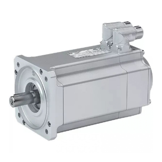
Product information Equipment Equipment The following figure provides an overview of the elements and connections on the product. Their position, size and appearance may vary. Motor connection Output flange Cooling Output shaft Feedback Spring-applied brake Temperature monitoring... -
Page 16: Transport
Transport Transport Ensure appropriate handling. • Make sure that all component parts are securely mounted. Secure or remove loose • component parts. Only use safely fixed transport aids (e.g., eye bolts or support plates). • Do not damage any components during transport. •... -
Page 17: Storage
Storage Storage Storage up to one year: If possible, in the manufacturer's packaging • In dry, low-vibration environment without aggressive atmosphere • Protect against dust and impacts • Observe the climatic conditions according to the technical data • 4Environmental conditions ^ 32... -
Page 18: Mechanical Installation
Ambient media − especially chemically aggressive ones − may damage shaft sealing rings, • lacquers and plastics. Lenze offers special surface and corrosion protection in this case. • Preparation Protect shaft sealing rings from contact with solvents. -
Page 19: Mounting
Mechanical installation Mounting Mounting Transmission elements Fit or remove transmission elements only using suitable equipment. • For fitting the transmission elements use the center hole in the shaft. • Avoid impacts and shocks. • In case of a belt drive, tension the belt in a controlled manner according to manufacturer •... -
Page 20: Electrical Installation
Use of filters, chokes • Use of special motor cables • Preparation The notes for the electrical connection can be found in the enclosed mounting instructions. EMC-compliant wiring The EMC-compliant wiring is described in detail in the documentation of the Lenze inverters. -
Page 21: Motor Connection
• Connection of temperature monitoring Motor/ICN connector assignment Standard connection: Power and brake One Cable Technology (OCT): Power connection, brake, feedback and temperature monitoring Motor Connector Motor Connector Motor Connector m850-S120/S3960 ICN-M23 m850-S140/S3240 ICN-M23 m850-S190/S3000 ICN-M23 m850-S120/M3960 ICN-M23 m850-S140/M3240 ICN-M23... - Page 22 Electrical installation Motor connection Connection via ICN connector Standard connection Connection of power and brake ICN-M23 connector assignment 6-pole ICN M23 6-pole Contact Name Meaning PE conductor Holding brake DC +/AC Holding brake DC -/AC Power phase U Power phase V Power phase W ICN-M40 connector assignment 8-pole...
- Page 23 Electrical installation Motor connection Connection via ICN connector Feedback and temperature monitoring connection ICN-M23 connector assignment Resolver Code 0° ICN M23 for resolvers Contact Name Meaning +Ref Transformer windings -Ref Transformer windings Supply: Electronic nameplate (Only for motors and inverters that support +VCC ETS this function) +COS...
- Page 24 Electrical installation Motor connection Connection via ICN connector One Cable Technology (OCT) Connection of power, brake, feedback and temperature monitoring ICN-M23 connector assignment, hybrid For One Cable Technology (OCT) with digital absolute value encoder ICN M23 Hybrid for One Cable Technology (OCT) with digital absolute value encoder Contact Name Meaning...
- Page 25 Electrical installation Motor connection Connection via ICN connector ICN-M40 connector assignment, hybrid For One Cable Technology (OCT) with digital absolute value encoder DSL1 DSL2 ICN M40 Hybrid for One Cable Technology (OCT) with digital absolute value encoder Contact Name Meaning Power phase U Power phase V Power phase W...
- Page 26 Electrical installation Motor connection Connection via ICN connector Assembly of ICN connectors NOTICE Live cables! Possible destruction of the connector. ▶ Never remove connector when voltage is being applied! ▶ Disable inverter before removing the connector! NOTICE Loss of the protection class due to incorrect mounting! Malfunctions may occur.
-
Page 27: Commissioning
Commissioning Important notes Commissioning Important notes NOTICE Do not brake the motor by short-circuit operation. Short-circuit braking may damage the motor. Before initial switch-on That the drive does not show any visible signs of damage. • Is the mechanical fixing o.k.? •... -
Page 28: Maintenance
Any work on the safety encoder which has not been executed professionally will cause a loss of the safety functions. Possible consequences: damage to property and/or injury to persons. ▶ The safety encoder may only be repaired or replaced by the Lenze service or its authorised persons. -
Page 29: Repair
First check the possible causes of malfunction according to the 4Diagnostics and fault • elimination ^ 30 If the fault cannot be remedied using one of the measures listed, please contact the Lenze • service department. The contact data can be found on the rear of this documentation. -
Page 30: Diagnostics And Fault Elimination
Adjust rated operating mode to the specified • Externally ventilated or self-ventilated motors 60034-1) exceeded operating conditions. Determination of correct > 110 °C drive by expert or Lenze customer service Loose contact in supply cable (temporary Tighten loose contact single-phase operation!) Fuse has blown (single-phasing!) -
Page 31: Technical Data
Technical data Standards and operating conditions Conformity and approvals Technical data Standards and operating conditions Conformity and approvals Conformities 2011/65/EU RoHS Directive 2014/30/EU EMC Directive (reference: CE-typical drive system) 2014/35/EU Low-Voltage Directive TP TC 020/2011 Eurasian conformity: Electromagnetic compatibility of technical means TP TR 004/2011 Eurasian conformity: Safety of low voltage equipment Approvals... -
Page 32: Environmental Conditions
Technical data Standards and operating conditions Environmental conditions Environmental conditions Climate 1K3 (-20 ... +40 °C) >3 months EN IEC Storage 60721-3-1:1997 1K3 (-20 ... +60 °C) <3 months EN IEC Transport 2K3 (-20 ... +70 °C) 60721-3-2:1997 EN IEC 3K3 (-10 ... -
Page 33: Rated Data
Technical data Rated data Inverter power supply 400 V, self-ventilated motors Rated data Inverter power supply 400 V, self-ventilated motors Motor M85AS120S40 M85AS120M4 M85AS120L40 M85AS140S32 M85AS140M3 M85AS140L32 Standstill torque 6.50 11.0 15.0 11.0 21.0 28.0 Rated torque 4.80 7.40 9.00 8.50 14.0 17.4... - Page 34 Technical data Rated data Inverter power supply 400 V, self-ventilated motors Motor M85AS190S30 M85AS190M30 M85AS190L25 Standstill torque 27.0 46.0 67.0 Rated torque 16.0 24.0 35.0 rated Max. torque 71.0 Rated speed 3000 3000 2520 rated Max. speed 4500 4500 4500 Rated power rated Standstill current...
-
Page 35: Environmental Notes And Recycling
Lenze products and their packaging: Lenze products are partly subject to the EU Directive 2011/65/EU on the restriction of certain hazardous substances in electrical and electronic equipment (RoHS). This is documented accordingly in the EU declaration of conformity and with the CE mark. - Page 36 Lenze SE Postfach 101352 · 31763 Hameln Hans-Lenze-Straße 1 · 31855 Aerzen GERMANY Hannover HRB 204803 Phone +49 5154 82-0 Fax +49 5154 82-2800 sales.de@lenze.com www.Lenze.com © 05/2021 · · 4.0 · www.Lenze.com...
Need help?
Do you have a question about the m850 and is the answer not in the manual?
Questions and answers