Lenze L-force 9400 Hardware Manual
E94a/e94b series
Hide thumbs
Also See for L-force 9400:
- Mounting instructions (206 pages) ,
- Manual (139 pages) ,
- Software manual (80 pages)

Related Manuals for Lenze L-force 9400


Summary of Contents for Lenze L-force 9400
- Page 1 EDS94SPP101 L−force Drives .W@D Hardware Manual 9400 E94A..., E94B... Servo Drives 9400...
- Page 2 0Fig. 0Tab. 0...
-
Page 3: Table Of Contents
............General safety and application notes for Lenze controllers . - Page 4 Contents Mechanical installation ..........3.6.1 Important notes .
- Page 5 Contents Wiring ............. . 4.7.1 Important notes .
- Page 6 Contents Rated data ............6.3.1 Overview .
- Page 7 Contents DC−bus variants ............7.3.1 Supply from a supply module .
- Page 8 Contents Function modules ........... . 8.4.1 Safety instructions .
- Page 9 Contents Components for operation in the DC−bus connection ..... . . 8.9.1 DC−feeding point ..........8.9.2 Busbar mounting set E94AZJA003 .
-
Page 10: Preface
Preface The 9400 Servo Drives product range The system Preface The 9400 Servo Drives product range 1.1.1 The system 9400 Servo Drives range is the product family with the components required for an intelligent servo drive system in automation. The product range comprises servo drive controllers ƒ... - Page 11 Preface The 9400 Servo Drives product range System overview > < SSP94SYS01 Mains voltage 3/PE AC 180 ... 528 V ±0 % or 3/PE AC 340 ... 528 V ±0 % (depending on the device size/device power) Mains fusing (not contained in the delivery programme) ^ 31 Single Drives 9400 and corresponding installation backplanes...
-
Page 12: About This Hardware Manual
The Table of Contents and Index help you to find all information about a certain ƒ topic. Descriptions and data of other Lenze products (drive PLC, Lenze geared motors, ƒ Lenze motors, ...) can be found in the corresponding catalogs, Operating Instructions and Manuals. -
Page 13: Products To Which The Hardware Manual Applies
Preface About this Hardware Manual Products to which the Hardware Manual applies 1.2.2 Products to which the Hardware Manual applies Power modules 1 2 3 8 9 10 13 14 15 16 17 18 − Type / product range 9400 Servo Drives Version A = 1. - Page 14 Preface About this Hardware Manual Products to which the Hardware Manual applies Extension modules 1 2 3 Type / product range 9400 Servo Drives Version A = 1. N = not relevant Identification Y = module Module group C = communication F = feedback M = memory A = safety...
- Page 15 Preface About this Hardware Manual Products to which the Hardware Manual applies Power−related accessories 1 2 3 9 10 11 Type / product range 9400 Servo Drives Version Identification Z = accessories Component class 1 H = brake control P = mounting backplane M = mains filter R = RFI filter Component class 2...
- Page 16 Preface About this Hardware Manual Products to which the Hardware Manual applies Power−independent accessories 1 2 3 7 8 9 Type / product range 9400 Servo Drives Version Identification Z = accessories Accessory group J = mechanical components, other S = software K = keypad N = not specified Module identification...
-
Page 17: Document History
Preface Document history Document history Material number Version Description .W@D 10.2 02/2018 TD29 Correction of device features 13543133 10.1 01/2018 TD29 Information on UL fuses added 13543135 10.0 12/2017 TD29 General corrections and standardisation 13514043 11/2016 TD29 New devices inserted; old devices removed New UL specifications in preparation Corrections 13480643... -
Page 18: Conventions Used
Preface Conventions used Conventions used This documentation uses the following conventions to distinguish between different types of information: Spelling of numbers Decimal separator Point In general, the decimal point is used. For instance: 1234.56 Warnings UL warnings Given in English and French UR warnings Text Program name... -
Page 19: Notes Used
Preface Notes used Notes used The following pictographs and signal words are used in this documentation to indicate dangers and important information: Safety instructions Structure of safety instructions: Danger! (characterises the type and severity of danger) Note (describes the danger and gives information about how to prevent dangerous situations) Pictograph and signal word Meaning... -
Page 20: Legal Regulations
Preface Legal regulations Legal regulations Labelling Lenze drive controllers are clearly labelled and defined by the contents of the nameplate. Manufacturer Lenze Automation GmbH, Postfach 10 13 52, 31763 Hameln, Hans−Lenze−Str. 1, 31855 Aerzen CE conformity Complies with the "Low voltage" EC Directive... - Page 21 Manual. The specifications, processes, and circuitry described in this Hardware Manual are for guidance only and must be adapted to your own application. Lenze does not take any responsibility for the suitability of the process and circuit proposals. The specifications in this Hardware Manual describe the product features without guaranteeing them.
-
Page 22: Terms And Abbreviations Used
Terms and abbreviations used Controller Any frequency inverter, servo inverter, or DC speed controller Axis, drive Lenze controller combined with a motor or geared motor and other Lenze drive components Basic insulation Insulation for the basic protection against dangerous shock currents... - Page 23 Preface Terms and abbreviations used Electromagnetic compatibility European standard International Electrotechnical Commission International Protection Code NEMA National Electrical Manufacturers Association Verband deutscher Elektrotechniker Communauté Européene Underwriters Laboratories EDS94SPP101 EN 10.2...
-
Page 24: Safety Instructions
– The procedural notes and circuit details described in this documentation are only proposals. It’s up to the user to check whether they can be transferred to the particular applications. Lenze Automation GmbH does not accept any liability for the suitability of the procedures and circuit proposals described. - Page 25 Safety instructions General safety and application notes for Lenze controllers Intended use Drive controllers are components designed for the installation in electrical systems or machinery. They must not be used as household appliances. They are intended exclusively professional and commercial purposes according to EN 61000−3−2.
- Page 26 Reduce housing openings and cutouts to a minimum. Lenze controllers may cause a DC current in the PE conductor. If a residual current device (RCD) is used for protection against direct or indirect contact for a controller with three−phase supply, only a residual current device (RCD) of type B is permissible on the...
-
Page 27: General Safety And Application Notes For Lenze Motors
Safety instructions General safety and application notes for Lenze motors General safety and application notes for Lenze motors (according to Low−Voltage Directive 2014/35/EU) General Low−voltage machines have dangerous, live and rotating parts as well as possibly hot surfaces. Synchronous machines induce voltages at open terminals during operation. - Page 28 Safety instructions General safety and application notes for Lenze motors Installation Ensure an even surface, solid foot/flange mounting and exact alignment if a direct clutch is connected. Avoid resonances with the rotational frequency and double mains frequency which may be caused by the assembly. Turn rotor by hand, listen for unusual slipping noises.
- Page 29 Safety instructions General safety and application notes for Lenze motors Commissioning and operation Before commissioning after longer storage periods, measure insulation resistance. In case of values £ 1 kW per volt of rated voltage, dry winding. For trial run without output elements, lock the featherkey. Do not deactivate the protective devices, not even in a trial run.
-
Page 30: Residual Hazards
Safety instructions Residual hazards Residual hazards Protection of persons Before working on the controller, check if no voltage is applied to the power ƒ terminals because – because the power terminals U, V, W, +UG, −UG, Rb1 and Rb2 carry hazardous voltages for up to 30 minutes after power−off depending on the device. -
Page 31: Single−Axis Controllers
Single−axis controllers Device features Single−axis controllers Device features Space−saving installation by compact design ƒ Innovative installation concept ƒ Power range: 370 W to 240 kW ƒ Pluggable and same connection system for the control cables in the entire power ƒ range Direct AC mains connection for "Single Drive"... -
Page 32: Overview Of The Devices
Single−axis controllers Overview of the devices Overview of the devices Note! For reasons of clarity, device types in this manual are placed together in groups with shared device characteristics. For example: "Devices in the range 2 ... 24 A (0.37 ... 11 kW)" (often from project planner’s ƒ... -
Page 33: General Data And Operating Conditions
Single−axis controllers General data and operating conditions General data and operating conditions General data Conformity and approval Conformity 2014/35/EU Low−Voltage Directive 2014/30/EU EMC Directive TP TC 004/2011 Regarding the safety of Eurasian conformity low−voltage equipment (TP ZU 004/2011) TR ZU: Technical regulation of the tariff union TP TC 020/2011 Electromagnetic... - Page 34 Single−axis controllers General data and operating conditions Protection of persons and device protection Type of protection EN 60529 IP 20 Outside the wire range of NEMA 250 Protection against accidental the terminals on the contact in accordance with motor side type 1 Insulation resistance EN 61800−5−1...
- Page 35 5 ... 13.2 Hz: Amplitude ±1 mm 13.2 ... 100 Hz: acceleration resistant up to 0.7 g Device size 81 ... 83: Mounting must be executed with vibration dampers by the customer. Please consult Lenze. Device size 91: The control cabinet has to be vibration−damped.
- Page 36 Single−axis controllers General data and operating conditions General electrical data Assignment Device size Accessories: busbar mounting set/spare fuse Axis module Installation backplane E94ASxE0024 E94AZPS0034 E94AZJA003: 16 A, 700 V DC / EFSAR0016ARHN E94ASxE0034 E94ASxE0044 E94AZPS0074 E94AZJA007: 40 A, 700 V DC / EFSAR0040ARHN E94ASxE0074 E94ASxE0134 E94ASxE0174...
- Page 37 Single−axis controllers General data and operating conditions Max. shielded motor cable lengths for compliance with the conducted interference emission according to C1/C2 Type with RFI filter with mains filter without filter E94ASxE0024 E94AZRS0044 E94AZMS0034 E94ASxE0034 −/50 m 25 m/50 m −/10 m E94ASxE0044 E94AZRS0104...
- Page 38 Single−axis controllers General data and operating conditions Max. shielded motor cable lengths for compliance with the conducted interference emission according to C3 Type with RFI filter with mains filter without filter E94BSxE1454 − − 150 m E94BSxE1724 − − 150 m E94BSxE2024 −...
- Page 39 Single−axis controllers General data and operating conditions Operation on public supply EN 61800−3 The controllers are designed for use in an industrial systems environment. Operation on public networks requires measures to be taken for limiting the expected emission of radio interferences. Noise emission, in cables Design EN 61800−3...
- Page 40 Single−axis controllers General data and operating conditions Protective insulation Danger! Dangerous electrical voltage When one common voltage source is used for control voltages in separate potential areas, the protective insulation between the separate potential areas is deactivated. Possible consequences: The specified protective insulations are not complied with. ƒ...
- Page 41 Single−axis controllers General data and operating conditions X100 MXI1 Protective insulation acc. to EN 61800−5−1 (Definition of terms: see glossary) Ext. DC MXI2 Functional insulation Basic insulation Reinforced insulation X107 X106 Ext. DC X105 X105 X105 X104 E94YCXX007 Terminal strip Connection Terminal strip Connection...
-
Page 42: Rated Data
Single−axis controllers Rated data Rated data The devices in the power range of 0.37 ... 55 kW (GG 1 ... 7) can be used in the voltage range of 180 ... 528 V AC. The devices in the power range of 75 ... 240 kW (GG 81 ... 91) can be used in the voltage range of 340 ... -
Page 43: Overview
Single−axis controllers Rated data Overview 3.4.1 Overview Input data Voltage Frequency Rated current [A] Number of phases up to +45 °C up to +55 °C [V AC] [Hz] [V DC] E94ASxE0024 230/400/480 50/60 2.1/2.1/1.8 1.6/1.6/1.4 325/565/675 2.6/2.6/2.3 1.9/1.9/1.7 −... - Page 44 Single−axis controllers Rated data Overview Output data Voltage Frequency Current [A] Number of phases Type [Hz] up to +45 °C up to +55 °C E94ASxE0024 0 − 230/400/480 0 − 599 1.5/1.5/1.3 1.1/1.1/1.0 E94ASxE0034 0 − 230/400/480 0 − 599 2.5/2.5/2.2 1.9/1.9/1.7 E94ASxE0044...
- Page 45 Single−axis controllers Rated data Overview Power losses Power loss P [W] at a switching frequency of 4 kHz Type = 230 V = 400 V = 480 V when controller is inhibited E94ASxE0024 E94ASxE0034 E94ASxE0044 E94ASxE0074 E94ASxE0134 E94ASxE0174 E94ASxE0244 E94ASxE0324 E94ASxE0474 1050 1050...
-
Page 46: Operation At Rated Mains Voltage 230 V
Single−axis controllers Rated data Operation at rated mains voltage 230 V 3.4.2 Operation at rated mains voltage 230 V Device size 1 ... 6 Mains Voltage Voltage range Frequency range f [Hz] Lrated Lrated 3/PE AC 180 − 0 % ... 264 + 0 % 45 −... - Page 47 Single−axis controllers Rated data Operation at rated mains voltage 230 V Device size 1 ... 91 Output currents [A] at switching frequency 2 kHz 4 kHz 8 kHz 16 kHz aN16 E94ASxE0024 E94ASxE0034 10.0 10.0 E94ASxE0044 16.0 16.0 12.8 E94ASxE0074 21.0 21.0 16.8...
- Page 48 Single−axis controllers Rated data Operation at rated mains voltage 230 V Rated data for internal brake chopper Bmin BRmax BRmax [kW] [kW] Type E94ASxE0024 0.64 E94ASxE0034 0.64 E94ASxE0044 14.4 0.95 E94ASxE0074 14.4 E94ASxE0134 21.7 10.6 E94ASxE0174 43.3 16.9 20.3 E94ASxE0244 43.3 16.9 24.5...
-
Page 49: Operation At Rated Mains Voltage 400 V
Single−axis controllers Rated data Operation at rated mains voltage 400 V 3.4.3 Operation at rated mains voltage 400 V Device size 1 ... 6 Mains Voltage Voltage range Frequency range f [Hz] Lrated Lrated 3/PE AC 320 − 0 % ... 440 + 0 % 45 −... - Page 50 Single−axis controllers Rated data Operation at rated mains voltage 400 V Device size 81 ... 91 Mains Voltage Voltage range Frequency range f [Hz] Lrated Lrated 3/PE AC 340 − 0 % ... 440 + 0 % 48 − 0 % ... 65 + 0 % ) Motor power Mains current at I Output power...
- Page 51 Single−axis controllers Rated data Operation at rated mains voltage 400 V Device size 1 ... 91 Output currents [A] at switching frequency 2 kHz 4 kHz 8 kHz 16 kHz aN16 E94ASxE0024 E94ASxE0034 10.0 10.0 E94ASxE0044 16.0 16.0 12.8 E94ASxE0074 21.0 21.0 16.8...
- Page 52 Single−axis controllers Rated data Operation at rated mains voltage 400 V Operation with increased continuous power If required, operation with increased continuous power can be activated for specific controllers at the switching frequency 2 kHz. This operating mode can only be performed under the following conditions: Inverters of the types E94BSxE1454 ...
- Page 53 Single−axis controllers Rated data Operation at rated mains voltage 400 V Sinusoidal filter assignments changed for this operating mode: Max. motor cable lengths for compliance with the conducted interference emission according to C2 when sinusoidal filters and line filters are used Setting C01199 Sine filter shielded...
- Page 54 Single−axis controllers Rated data Operation at rated mains voltage 400 V Rated data for internal brake chopper Bmin BRmax BRmax [kW] [kW] Type E94ASxE0024 E94ASxE0034 E94ASxE0044 15.4 11.2 E94ASxE0074 15.4 11.2 E94ASxE0134 26.9 19.5 13.2 E94ASxE0174 40.3 29.2 18.9 E94ASxE0244 40.3 29.2 22.8...
-
Page 55: Operation With Rated Mains Voltage 480 V
Single−axis controllers Rated data Operation with rated mains voltage 480 V 3.4.4 Operation with rated mains voltage 480 V Device size 1 ... 6 Mains Voltage Voltage range Frequency range f [Hz] Lrated Lrated 3/PE AC 340 − 0 % ... 528 + 0 % 45 −... - Page 56 Single−axis controllers Rated data Operation with rated mains voltage 480 V Device size 81 ... 91 Mains Voltage Voltage range Frequency range f [Hz] Lrated Lrated 3/PE AC 340 − 0 % ... 528 + 0 % 45 − 0 % ... 65 + 0 % ) Motor power Mains current at I Output power...
- Page 57 Single−axis controllers Rated data Operation with rated mains voltage 480 V Device size 1 ... 91 Output currents [A] at switching frequency 2 kHz 4 kHz 8 kHz 16 kHz aN16 E94ASxE0024 E94ASxE0034 10.0 10.0 E94ASxE0044 16.0 16.0 11.2 E94ASxE0074 21.0 21.0 14.7...
- Page 58 Single−axis controllers Rated data Operation with rated mains voltage 480 V Operation with increased continuous power If required, operation with increased continuous power can be activated for specific controllers at the switching frequency 2 kHz. This operating mode can only be performed under the following conditions: Inverters of the types E94BSxE1454 ...
- Page 59 Single−axis controllers Rated data Operation with rated mains voltage 480 V Sinusoidal filter assignments changed for this operating mode: Max. motor cable lengths for compliance with the conducted interference emission according to C2 when sinusoidal filters and line filters are used Setting C01199 Sine filter shielded...
- Page 60 Single−axis controllers Rated data Operation with rated mains voltage 480 V Rated data for internal brake chopper Bmin BRmax BRmax [kW] [kW] Type E94ASxE0024 E94ASxE0034 E94ASxE0044 16.3 12.5 E94ASxE0074 16.3 12.5 E94ASxE0134 28.3 21.7 13.9 E94ASxE0174 42.5 32.5 19.9 E94ASxE0244 42.5 32.5 24.0...
-
Page 61: Fuses And Cable Cross−Sections
Single−axis controllers Rated data Fuses and cable cross−sections 3.4.5 Fuses and cable cross−sections The recommendations for the dimensioning of fuses and cable cross−sections apply to the operation of devices with the assigned typical motor ratings and indicated installation conditions. In the case of other permissible operating modes, e.g. additional use of reserve power in the interconnected system, the dimensioning of fuses and cables must be adapted to the ratings and currents in accordance with the relevant technical standards. - Page 62 Single−axis controllers Rated data Fuses and cable cross−sections Operation with external mains choke/mains filter, installation according to UL Only use UL−approved cables, fuses and fuse holders. UL fuse: Voltage 600 V; CC, J or T class fuses Type standard installation motor group installation ...
- Page 63 Single−axis controllers Rated data Fuses and cable cross−sections Operation without external mains choke/mains filter, installation according to EN 60204−1 The data are recommendations. Other dimensioning/laying systems are possible (e.g. according VDE 0298−4). The cable cross−sections apply under the following conditions: Use of PVC−insulated copper cables ƒ...
- Page 64 Single−axis controllers Rated data Fuses and cable cross−sections Operation without external mains choke/mains filter, installation according to UL Only use UL−approved cables, fuses and fuse holders. UL fuse: Voltage 600 V; CC, J or T class fuses Type standard installation motor group installation ...
-
Page 65: Overcurrent Operation
Single−axis controllers Rated data Overcurrent operation 3.4.6 Overcurrent operation The controllers are designed for two overcurrent modes. A load period must be followed by a recovery time. During the recovery time the current must not exceed the value given. The values given refer to the rated output current I ... - Page 66 Single−axis controllers Rated data Overcurrent operation 230 V E94ASxE0024 ... E94ASxE1044: I [A] in a cycle of 5 seconds (^ 65) Type f = 2 kHz f = 4 kHz f = 8 kHz f = 16 kHz E94ASxE0024 −...
- Page 67 Single−axis controllers Rated data Overcurrent operation 400 V E94ASxE0024 ... E94ASxE1044: I [A] in a cycle of 5 seconds (^ 65) Type f = 2 kHz f = 4 kHz f = 8 kHz f = 16 kHz E94ASxE0024 −...
- Page 68 Single−axis controllers Rated data Overcurrent operation E94BSxE1454 ... E94BSxE4604: I [A] in a cycle of 1 minute (^ 65) Type f = 2 kHz f = 4 kHz f = 8 kHz f = 16 kHz E94BSxE1454 81.2 − −...
- Page 69 Single−axis controllers Rated data Overcurrent operation 480 V E94ASxE0024 ... E94ASxE1044: I [A] in a cycle of 5 seconds (^ 65) Type f = 2 kHz f = 4 kHz f = 8 kHz f = 16 kHz E94ASxE0024 −...
- Page 70 Single−axis controllers Rated data Overcurrent operation E94BSxE1454 ... E94BSxE4604: I [A] in a cycle of 1 minute (^ 65) Type f = 2 kHz f = 4 kHz f = 8 kHz f = 16 kHz E94BSxE1454 81.2 − −...
-
Page 71: Current−Time Diagrams
Single−axis controllers Rated data Current−time diagrams 3.4.7 Current−time diagrams In addition to the data for overcurrent operation, here you are provided with information on the dimensioning of application−oriented cycles. By means of the following information you determine permissible load periods with overcurrents and required recovery times with limited currents. - Page 72 Single−axis controllers Rated data Current−time diagrams Application example Drive task ƒ – A current I = 4.0 A is required for a time t = 3 s. – During the recovery phase there is a current I = 1.0 A. –...
- Page 73 Single−axis controllers Rated data Current−time diagrams Guide Type Diagram E94AxxE0024 Page ^ 74 E94AxxE0034 ^ Fig. 3−2/ ^ Fig. 3−3 E94AxxE0044 E94AxxE0074 E94AxxE0134 Page ^ 75 E94AxxE0174 ^ Fig. 3−4/ ^ Fig. 3−5 E94AxxE0244 E94AMxE0324 E94AxxE0474 Page ^ 77 ^ Fig. 3−8 / ^ Fig. 3−9 E94AxxE0594 E94ASxE0864 Page ^ 78...
- Page 74 Single−axis controllers Rated data Current−time diagrams E94AxxE0024 ... E94AxxE0044 Type 100 % chopp [Setting] E94AxxE0024 E94AxxE0034 8 kHz var E94AxxE0044 150 % 150 % 175 % 175 % 200 % 200 % 225 % 225 % 25 % 25 % 50 % 50 % 60 % 60 %...
- Page 75 Single−axis controllers Rated data Current−time diagrams E94AxxE0074 ... E94AxxE0244 and E94AMxE0324 Type 100 % chopp [Setting] E94AxxE0074 8 kHz var E94AMxE0094 8 kHz var E94AxxE0134 13.0 E94AxxE0174 16.5 8 kHz var E94AxxE0244 23.5 E94AMxE0324 32.0 8 kHz var 150 % 150 % 175 % 175 % 200 %...
- Page 76 Single−axis controllers Rated data Current−time diagrams E94AxxE0324 Type 100 % chopp [Setting] E94AxxE0324 32.0 4 kHz var 180 % 180 % 210 % 210 % 240 % 240 % 25 % 25 % 50 % 50 % 60 % 60 % 75 % 75 % t [s]...
- Page 77 Single−axis controllers Rated data Current−time diagrams E94AxxE0474 and E94AxxE0594 Type 100 % chopp [Setting] E94AxxE0474 47.0 4 kHz var E94AxxE0594 59.0 7 5 % 7 5 % 150 % 150 % 175 % 175 % 200 % 200 % 25 % 25 % 50 % 50 % 60 %...
- Page 78 Single−axis controllers Rated data Current−time diagrams E94AxxE0864 and E94AxxE1044 Type 100 % chopp [Setting] E94AxxE0864 86.0 4 kHz var E94AxxE1044 75 % 75 % 150 % 150 % 175 % 175 % 200 % 200 % 25 % 25 % 50 % 50 % 60 %...
- Page 79 Single−axis controllers Rated data Current−time diagrams E94BxxE1454 ... E94BxxE4604 Type 100 % chopp [Setting] E94BxxE1454 E94BxxE1724 4 kHz var E94BxxE2024 E94BxxE2454 E94BxxE2924 2 kHz var E94BxxE3664 E94BxxE4604 150 % 150 % 165 % 165 % 180 % 180 % 0 % 25 % 25 % 50 % 50 % 60 %...
-
Page 80: Device Description
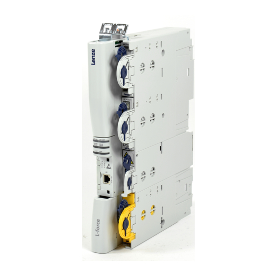
Single−axis controllers Device description Devices in the range 2 ... 24 A (0.37 ... 11 kW) Device description 3.5.1 Devices in the range 2 ... 24 A (0.37 ... 11 kW) 9400SSP012 EDS94SPP101 EN 10.2... - Page 81 Single−axis controllers Device description Devices in the range 2 ... 24 A (0.37 ... 11 kW) Standard device 0 Pos. Description MXI1 Module receptacle for extension 1, e.g. communication MXI2 Module receptacle for extension 2, e.g. communication Module receptacle for memory modules Module receptacle for safety equipment System bus (CAN), under the cover 24 V supply and statebus...
-
Page 82: Devices In The Range 32
Single−axis controllers Device description Devices in the range 32 ... 104 A (15 ... 55 kW) 3.5.2 Devices in the range 32 ... 104 A (15 ... 55 kW) SSP94GG612 EDS94SPP101 EN 10.2... - Page 83 Single−axis controllers Device description Devices in the range 32 ... 104 A (15 ... 55 kW) Standard device 0 Pos. Description MXI1 Module receptacle for extension 1, e.g. communication MXI2 Module receptacle for extension 2, e.g. communication Module receptacle for memory modules Module receptacle for safety equipment System bus (CAN), under the cover 24 V supply and statebus...
-
Page 84: Devices In The Range 145
Single−axis controllers Device description Devices in the range 145 ... 245 A (75 ... 130 kW) 3.5.3 Devices in the range 145 ... 245 A (75 ... 130 kW) SSP94GG812 The control unit is firmly connected to the device. For a better presentation, it has been removed. - Page 85 Single−axis controllers Device description Devices in the range 145 ... 245 A (75 ... 130 kW) Pos. Description MXI1 Module receptacle for extension 1, e.g. communication MXI2 Module receptacle for extension 2, e.g. communication Module receptacle for memory modules Module receptacle for safety equipment System bus (CAN), under the cover 24−V supply / Statebus Analog inputs / analog outputs...
-
Page 86: Device 292 A (150 Kw)
Single−axis controllers Device description Device 292 A (150 kW) 3.5.4 Device 292 A (150 kW) SSP94GG814 The control unit is firmly connected to the device. For a better presentation, it has been removed. EDS94SPP101 EN 10.2... - Page 87 Single−axis controllers Device description Device 292 A (150 kW) Pos. Description MXI1 Module receptacle for extension 1, e.g. communication MXI2 Module receptacle for extension 2, e.g. communication Module receptacle for memory modules Module receptacle for safety equipment System bus (CAN), under the cover 24−V supply / Statebus Analog inputs / analog outputs Digital outputs...
-
Page 88: Devices In The Range 366
Single−axis controllers Device description Devices in the range 366 ... 460 A (190 ... 240 kW) 3.5.5 Devices in the range 366 ... 460 A (190 ... 240 kW) SSP94GG813 The control unit is firmly connected to the device. For a better presentation, it has been removed. - Page 89 Single−axis controllers Device description Devices in the range 366 ... 460 A (190 ... 240 kW) Pos. Description MXI1 Module receptacle for extension 1, e.g. communication MXI2 Module receptacle for extension 2, e.g. communication Module receptacle for memory modules Module receptacle for safety equipment System bus (CAN), under the cover 24−V supply / Statebus Analog inputs / analog outputs...
-
Page 90: Mechanical Installation
Single−axis controllers Mechanical installation Important notes Mechanical installation 3.6.1 Important notes Note! The devices must be installed in housings (e.g. control cabinets) to meet applicable regulations. The mounting location must always comply with the operating conditions specified ƒ in the technical data (¶ 33). Take additional measures if necessary. The mounting plate of the control cabinet must have the following properties: ƒ... -
Page 91: Devices In The Range 2
Single−axis controllers Mechanical installation Devices in the range 2 ... 24 A (0.37 ... 11 kW) 3.6.2 Devices in the range 2 ... 24 A (0.37 ... 11 kW) Mounting grid We recommend to provide the mounting plate with a grid pattern of M5 threaded holes for attaching the devices. - Page 92 Single−axis controllers Mechanical installation Devices in the range 2 ... 24 A (0.37 ... 11 kW) Standard device with installation backplane SSP94GGmSo000 Fig. 3−15 Dimensions [mm] Type Dimensions a Mass Device size [mm] [kg] E94ASxE0024 E94ASxE0034 E94ASxE0044 E94ASxE0074 E94ASxE0134 E94ASxE0174 E94ASxE0244 EDS94SPP101 EN 10.2...
- Page 93 Single−axis controllers Mechanical installation Devices in the range 2 ... 24 A (0.37 ... 11 kW) Installation steps Proceed as follows for the installation: 1. Prepare M5 threaded holes on the mounting plate according to the mounting grid. 2. When using footprint filters: Screw installation backplane and footprint filter together.
-
Page 94: Devices In The Range 32
Single−axis controllers Mechanical installation Devices in the range 32 ... 104 A (15 ... 55 kW) 3.6.3 Devices in the range 32 ... 104 A (15 ... 55 kW) SSP94Mas01 Fig. 3−16 Dimensions [mm] Dimensions [mm] Weight Device size Type [kg] E94ASxE0324 E94ASxE0474... -
Page 95: Devices In The Range 145
Single−axis controllers Mechanical installation Devices in the range 145 ... 292 A (75 ... 150 kW) 3.6.4 Devices in the range 145 ... 292 A (75 ... 150 kW) 22.5 SSP94GG8x1 Fig. 3−17 Dimensions [mm] Dimensions [mm] Mass Device size Type [kg] E94BSxE1454... -
Page 96: Devices In The Range 366
Single−axis controllers Mechanical installation Devices in the range 366 ... 460 A (190 ... 240 kW) 3.6.5 Devices in the range 366 ... 460 A (190 ... 240 kW) SSP94GG921 Fig. 3−18 Dimensions [mm] Mass Device size Type [kg] E94BSxE3664 E94BSxE4604 EDS94SPP101 EN 10.2... -
Page 97: Wiring
Single−axis controllers Wiring Important notes Wiring 3.7.1 Important notes Danger! Hazardous electrical voltage All power connections carry a hazardous electrical voltage for a longer time after mains disconnection. Observe the information regarding the discharge time on the device. Possible consequences: Death or severe injuries when touching the power terminals. - Page 98 Single−axis controllers Wiring Important notes Stop! No device protection if the mains voltage is too high The mains input is not internally fused. Possible consequences: Destruction of the device if the mains voltage is too high. ƒ Protective measures: Observe the maximally permissible mains voltage. ƒ...
-
Page 99: Safety Instructions For The Installation According To Ul/Csa
Single−axis controllers Wiring Safety instructions for the installation according to UL/CSA 3.7.2 Safety instructions for the installation according to UL/CSA Original − English Device size 1 ... 3 Warnings! Branch circuit protection: ƒ – Suitable for use on a circuit capable of delivering not more than 100 000 rms symmetrical amperes, 480 V max., when protected by CC, J or T class fuses. - Page 100 Single−axis controllers Wiring Safety instructions for the installation according to UL/CSA Branch circuit/short circuit protection with fuses in accordance with UL248 Type standard installation motor group installation Fuse [A] Fuse [A] E94ASxE0024 E94ASxE0034 E94ASxE0044 E94ASxE0074 E94ASxE0134 E94ASxE0174 E94ASxE0244 Assignment of devices − DC−fuses +UG/−UG (X100) Busbar (X109/X110) Nominal value (max.)
- Page 101 Single−axis controllers Wiring Safety instructions for the installation according to UL/CSA Device size 6 and 7 Warnings! Branch circuit protection: ƒ – Suitable for use on a circuit capable of delivering not more than 100 000 rms symmetrical amperes, 480 V max., when protected by CC, J or T class fuses.
- Page 102 Single−axis controllers Wiring Safety instructions for the installation according to UL/CSA Device size 81 ... 91 E94BSxE1454 (145 A, 75 kW) ... E94BSxE2024 (202 A, 105 kW), E94BSxE3664 (366 A, 190 kW) ... E94BSxE4604 (460 A, 240 kW): Warnings! Branch circuit protection: ƒ...
- Page 103 Single−axis controllers Wiring Safety instructions for the installation according to UL/CSA Original − French Wiring Safety instructions for the installation according to UL/CSA Device size 1 ... 3 Avertissement ! Protection par disjoncteur : ƒ – Convient aux circuits non susceptibles de délivrer plus de 100 000 ampères symétriques eff., maximum 480 V, avec protection par des fusibles de calibre CC, J, ou T.
- Page 104 Single−axis controllers Wiring Safety instructions for the installation according to UL/CSA Température ambiante maximale : 45 °C ƒ Température ambiante maximale avec réduction de puissance : 55 °C ƒ Utiliser exclusivement des conducteurs en cuivre 60/75 °C, sauf pour la ƒ...
- Page 105 Single−axis controllers Wiring Safety instructions for the installation according to UL/CSA Device size 6 and 7 Avertissement ! Protection par disjoncteur : ƒ – Convient aux circuits non susceptibles de délivrer plus de 100000 ampères symétriques eff., maximum 480 V, avec protection par des fusibles de calibre CC, J, ou T.
- Page 106 Single−axis controllers Wiring Safety instructions for the installation according to UL/CSA Protection du circuit de dérivation / protection contre les courts−circuits par fusibles conformément à UL248 Type Installation standard Installation au sein d´un groupe moteur Fusible [A] Fusible [A] E94ASxE0324 E94ASxE0474 E94ASxE0594 E94ASxE0864...
- Page 107 Single−axis controllers Wiring Safety instructions for the installation according to UL/CSA Device size 81 ... 91 E94BSxE1454 (145 A, 75 kW) ... E94BSxE2024 (202 A, 105 kW), E94BSxE3664 (366 A, 190 kW) ... E94BSxE4604 (460 A, 240 kW): Avertissement ! Protection par disjoncteur : ƒ...
-
Page 108: Earthing Of Internal Emc Filters
Single−axis controllers Wiring Earthing of internal EMC filters 3.7.3 Earthing of internal EMC filters Device−internal EMC filters have been implemented to reduce interference emission. These EMC filters are connected to protective earth to discharge interference currents. Under certain conditions the EMC filters must be disconnected from: Operation in an IT system ƒ... - Page 109 Single−axis controllers Wiring Safety instructions for the installation according to UL/CSA Device size 1 ... 3 Proceed as follows to disconnect the internal connection between the filters and PE: 1. Remove IT insulating cap from the parking position in the installation backplane. –...
- Page 110 Single−axis controllers Wiring Safety instructions for the installation according to UL/CSA Device size 6 and 7 Proceed as follows to disconnect the internal connection between the filters and PE: 94GG67IT67 Fig. 3−20 1. There is a screw above the X100 (+UG/−UG) terminals in the position "TT−TN". 2.
- Page 111 Single−axis controllers Wiring Safety instructions for the installation according to UL/CSA Device sizes 81 and 82 Proceed as follows to disconnect the internal connection between the filters and PE: 1. The bridge 0 that connects the filter with the protective earth can be found at the indicated position.
- Page 112 Single−axis controllers Wiring Safety instructions for the installation according to UL/CSA Device size 83 Proceed as follows to disconnect the internal connection between the filters and PE: 1. The bridge 0 that connects the filter with the protective earth can be found at the indicated position.
-
Page 113: Devices In The Range 2
Single−axis controllers Wiring Devices in the range 2 ... 24 A (0.37 ... 11 kW) 3.7.4 Devices in the range 2 ... 24 A (0.37 ... 11 kW) Example circuit F1...F3 E94AZPxxxxx X100 E94ASxExxxx . . . X106 X105 X107 U V W EYF... - Page 114 Single−axis controllers Wiring Devices in the range 2 ... 24 A (0.37 ... 11 kW) Design of the cables The cables used must comply with the approvals required for the location (e.g. UL). ƒ The cross−section of the PE conductor must be dimensioned according to the ƒ...
- Page 115 Single−axis controllers Wiring Devices in the range 2 ... 24 A (0.37 ... 11 kW) Mains Terminal X100 Labelling Description (left part) Connection of the mains phases L1, L2, L3 SSP940X100 Connection for the supply−side PE conductor with M5 ring cable lug Terminal data Max.
- Page 116 Single−axis controllers Wiring Devices in the range 2 ... 24 A (0.37 ... 11 kW) External brake resistor Terminal X105 Labelling Description (left part) External brake resistor SSP94LX105 Connection for the PE conductor with M5 ring cable lug. Terminal data Max.
- Page 117 Single−axis controllers Wiring Devices in the range 2 ... 24 A (0.37 ... 11 kW) Motor Terminal X105 Labelling Description (right part) Connection of the motor phases " Functional earth Connect the shields of the motor phases and of the optional motor brake control separately and with a surface as large as possible to the shield sheet.
- Page 118 Single−axis controllers Wiring Devices in the range 2 ... 24 A (0.37 ... 11 kW) BD1/T1 BD2/T2 SSP94MOTL1 Fig. 3−22 Stripping lengths of the motor cable Dimensions [mm] Type Device size 1 Device size 2 Device size 3 How to proceed: 1.
- Page 119 Accessories starting on page 451. Terminal X107 Labelling Description Connection of the motor holding brake + (Lenze: WH) − (Lenze: BN) E94AZHX0051: 24 V DC, max. 2.5 A Observe correct polarity! + / − Supply voltage for the motor holding brake (18 ... 30 V DC)
- Page 120 – Operation with unshielded brake cables can destroy the motor brake control. – We recommend the use of Lenze system cables (motor cable with separately shielded additional cores). When using a permanent magnet holding brake, ensure the correct polarity ƒ...
- Page 121 Single−axis controllers Wiring Devices in the range 2 ... 24 A (0.37 ... 11 kW) Installation of the standard device After the wiring of the installation backplane has been fully completed, install the standard device. Then continue with the wiring of the control terminals. How to proceed: 1.
-
Page 122: Devices In The Range 32
Single−axis controllers Wiring Devices in the range 32 ... 104 A (15 ... 55 kW) 3.7.5 Devices in the range 32 ... 104 A (15 ... 55 kW) Example circuit F1...F3 ƒ " X100 E94ASxExxxx X106 X105 X107 T1 T2 Rb1 Rb2 BD1 BD2 "... - Page 123 Single−axis controllers Wiring Devices in the range 32 ... 104 A (15 ... 55 kW) Design of the cables The cables used must comply with the approvals required for the location (e.g. UL). ƒ The cross−section of the PE conductor must be dimensioned according to the ƒ...
- Page 124 Single−axis controllers Wiring Devices in the range 32 ... 104 A (15 ... 55 kW) Mains Terminal X100 Labelling Description (left part) Connection of the mains phases L1, L2, L3 Connection for the PE conductor on the supply side SSP94X6100 Terminal data Max.
- Page 125 Single−axis controllers Wiring Devices in the range 32 ... 104 A (15 ... 55 kW) External brake resistor Terminal X105 Labelling Description (left part) External brake resistor Connection for the PE conductor with M5 ring cable lug SSP94X6105 Terminal data Max.
- Page 126 Accessories starting on page 451. Terminal X107 Labelling Description Connection of the motor holding brake + (Lenze: WH) − (Lenze: BN) E94AZHx0101: 24 V DC, max. 5.0 A Observe correct polarity! + / − Supply voltage for the motor holding brake (18 ... 30 V DC)
-
Page 127: Devices In The Range 145
Single−axis controllers Wiring Devices in the range 145 ... 245 A (75 ... 130 kW) 3.7.6 Devices in the range 145 ... 245 A (75 ... 130 kW) Example circuit F1...F3 ƒ „ X100 X100 X104 E94BSxExxxx X106 X105 X107 BD1 BD2 T1 T2... - Page 128 Single−axis controllers Wiring Devices in the range 145 ... 245 A (75 ... 130 kW) Design of the cables The cables used must comply with the approvals required for the location (e.g. UL). ƒ The cross−section of the PE conductor must be dimensioned according to the ƒ...
- Page 129 Single−axis controllers Wiring Devices in the range 145 ... 245 A (75 ... 130 kW) Arrangement of the connections SSP94KL08S Fig. 3−26 Arrangement of the power connections EDS94SPP101 EN 10.2...
- Page 130 Single−axis controllers Wiring Devices in the range 145 ... 245 A (75 ... 130 kW) Mains Terminal X100 Labelling Description Connection of the mains phases L1, L2, L3. 0: Terminal (scope of supply); conductor connection with wire end ferrule 1: Threaded bolt M10 (at the device) 2: Ring cable lug for M10 (not included in the scope of supply) 3: Sleeve (scope of supply) Wiring:...
- Page 131 Single−axis controllers Wiring Devices in the range 145 ... 245 A (75 ... 130 kW) DC bus and external brake resistor Terminal X104 Labelling Description −UG Connection for DC−bus voltage and external brake resistor 0: Terminal (scope of supply); conductor connection with wire end +UG/Rb1 ferrule 1: M8 threaded bolt (GG81)/M10 (GG82)
- Page 132 Single−axis controllers Wiring Devices in the range 145 ... 245 A (75 ... 130 kW) Motor Terminal X105 Labelling Description Connection of the motor phases U, V, W 0: Terminal (scope of supply); conductor connection with wire end ferrule 1: Threaded bolt M10 (at the device) 2: Ring cable lug for M10 (not included in the scope of supply) 3: Sleeve (scope of supply) Wiring:...
- Page 133 Accessories starting on page 451. Terminal X107 Labelling Description Connection of the motor holding brake + (Lenze: WH) − (Lenze: BN) E94AZHx0101: 24 V DC, max. 5.0 A Observe correct polarity! + / − Supply voltage for the motor holding brake (18 ... 30 V DC)
-
Page 134: Device 292 A (150 Kw)
Single−axis controllers Wiring Device 292 A (150 kW) 3.7.7 Device 292 A (150 kW) Arrangement of the connections SSP94KL191 Fig. 3−27 Arrangement of the power connections EDS94SPP101 EN 10.2... - Page 135 Single−axis controllers Wiring Device 292 A (150 kW) Mains Terminal X100 Labelling Description Connection of phases L1, L2, L3 with ring cable lug for M10 (0). L1 L2 L3 SSP94KL191 Terminal data Max. conductor cross−section Tightening torque [AWG] [Nm] [lb−in] L1, L2, L3, flexible 500 mcm SW17...
- Page 136 Single−axis controllers Wiring Device 292 A (150 kW) DC bus and external brake resistor Terminal X104 Labelling Description −UG Connection for DC−bus voltage and external brake resistor with ring cable lug for M8 (0). +UG/Rb1 -UG +UG/Rb1 Rb2 SSP94KL191 Terminal data Max.
- Page 137 Single−axis controllers Wiring Device 292 A (150 kW) Motor Terminal X105 Labelling Description Connection of phases U, V, W with ring cable lug for M10 (0). U V W SSP94KL191 Terminal data Max. conductor cross−section Tightening torque [AWG] [Nm] [lb−in] U, V, W, flexible 500 mcm SW17...
- Page 138 The motor holding brake cannot be released without mains or DC−bus voltage. Terminal X107 Labelling Description Connection of the motor holding brake + (Lenze: WH) − (Lenze: BN) E94AZHx0101: 24 V DC, max. 5.0 A Observe correct polarity! + / −...
- Page 139 Single−axis controllers Wiring Device 292 A (150 kW) The motor brake control modules differ in the following features: Rated voltage ƒ Device size assignment ƒ Mounting type ƒ The table shows the module/controller assignments according to the features listed. Single−axis controllers Rated voltage of motor holding brake (control module) Type 24 V...
-
Page 140: Devices In The Range 366
Voltage source of the brake ƒ 24 V voltage source for the digital inputs according to IEC 61131−2 „ 24 V voltage source for the control electronics Note! If you use the DC bus differently, please consult Lenze. EDS94SPP101 EN 10.2... - Page 141 Single−axis controllers Wiring Devices in the range 366 ... 460 A (190 ... 240 kW) Design of the cables The cables used must comply with the approvals required for the location (e.g. UL). ƒ The cross−section of the PE conductor must be dimensioned according to the ƒ...
- Page 142 Single−axis controllers Wiring Devices in the range 366 ... 460 A (190 ... 240 kW) Arrangement of the connections X104.1 X104.2 X107 X106 X100 X105 SSP94KL191 Fig. 3−29 Arrangement of the power connections EDS94SPP101 EN 10.2...
- Page 143 Single−axis controllers Wiring Devices in the range 366 ... 460 A (190 ... 240 kW) Mains Terminal X100 Labelling Description Connection of the phases L1, L2, L3 with ring cable lug for M16 (0). Connection for the PE conductor on the supply side with ring cable lug for M10 (0).
- Page 144 Single−axis controllers Wiring Devices in the range 366 ... 460 A (190 ... 240 kW) Motor Terminal X105 Labelling Description Connection of the phases U, V, W with ring cable lug for M16 (0). Connection for the PE conductor on the motor side with ring cable lug for M10 (0).
- Page 145 Accessories starting on page 451. Terminal X107 Labelling Description Connection of the motor holding brake + (Lenze: WH) − (Lenze: BN) E94AZHx0101: 24 V DC, max. 5.0 A Observe correct polarity! + / − Supply voltage for the motor holding brake (18 ... 30 V DC)
-
Page 146: Control Terminals
Single−axis controllers Control terminals Control terminals Danger! Hazardous electrical voltage All power connections carry a hazardous electrical voltage for a longer time after mains disconnection. Observe the information regarding the discharge time on the device. Possible consequences: Death or severe injuries when touching the power terminals. ƒ... - Page 147 Single−axis controllers Control terminals Design of the cables The cables used must comply with the approvals required for the location (e.g. UL). ƒ The effectiveness of a shielded cable is reached by: ƒ – Providing a good shield connection through large−surface shield contact. –...
- Page 148 Communication medium CAN cable in accordance with ISO 11898−2 Network topology Line closed at both ends (e.g. closed with Lenze system connector EWZ0046) Node addresses that can be set 1 ... 127 (can be set by means of DIP switch or code) Max.
- Page 149 Single−axis controllers Control terminals Terminal X1 Labelling Description Pin 2 CAN−LOW Pin 3 CAN−GND Pin 7 CAN−HIGH 9400SSP000X1 (Housing) CAN−Shield 24 V supply The supply voltage for the control electronics should be fed by a mains−independent 24 V source. Thus, the control functions remain active even after power is removed. As an option, the controller can generate the supply voltage for the control electronics from the DC−bus voltage.
- Page 150 Single−axis controllers Control terminals Terminal X2 Labelling Description GND external supply 24 V external supply via a safely separated power supply unit (SELV/PELV) (only required for mains−independent supply of the control electronics) 9400SSP000X2 State bus in/out (reference GE) Terminal data Conductor cross−section Tightening torque [AWG]...
- Page 151 Control terminals State bus The state bus is a bus system exclusively designed for Lenze controllers via which up to 20 controllers can be connected and which serves to simulate a "release cord" function. The state is controlled via the system module SFBDigitalOutput.
- Page 152 Single−axis controllers Control terminals Analog inputs, analog outputs The controller features two analog inputs which are able to detect differential voltage signals in the range ±10 V, e.g. an analog speed setpoint selection or the voltage signal of an external sensor (temperature, pressure, etc.). The analog signal 1 can also detect a current setpoint.
- Page 153 Single−axis controllers Control terminals SSP94X3AIO Fig. 3−31 Wiring principle Wiring of an external analog signal Wiring with a slave drive Wiring with a measuring device Potentiometer supplied by analog output 1 Potentiometer with external supply Analog output signal, e.g. of a control Earth reference potential Terminal for the analog inputs and outputs EMC shield connection...
- Page 154 Single−axis controllers Control terminals Terminal X3 Labelling Description GND analog signals Analog output 1 Analog output 2 Analog input 1 + A1− Analog input 1 − A1− Analog input 1 − Terminating resistor for ±20mA Analog input 2 + A2− Analog input 2 −...
- Page 155 Single−axis controllers Control terminals Digital outputs The controller features four freely configurable digital outputs. Electrical data 24 V external voltage source, optional according to IEC 61131−2 SELV/PELV Current consumption Max. 300 mA Switching level according to IEC 61131−2 0 V ... +5 V HIGH +15 V ...
- Page 156 Single−axis controllers Control terminals Terminal X4 Labelling Description GND digital out 24−V digital out Digital output 1 Digital output 2 Digital output 3 9400SSP000X4 Digital output 4 Terminal data Conductor cross−section Tightening torque [AWG] [Nm] [lb−in] Flexible 0.2 ... 2.5 24 ...
- Page 157 Single−axis controllers Control terminals Digital inputs The controller is provided with freely configurable digital inputs which can be used for touch probe measurement (edge−controlled event). The control input RFR for controller enable is firmly connected with the device control. It must be wired to enable the controller with a HIGH signal.
- Page 158 USB diagnostic adapter E94AZCUS ƒ Keypad E94AZKAE. ƒ The diagnostic adapter and a computer with the Lenze software »Engineer« serve to carry out comprehensive settings, e.g. for initial commissioning. The keypad enables experienced users to check or change individual settings. Terminal X6...
- Page 159 Single−axis controllers Control terminals Resolver Resolvers are connected to X7 (9−pole Sub−D socket). The use of third−party resolvers is permissible. For this purpose the number of pole pairs of the resolver in C00080 must be adapted to the resolver used. When the stator coils are excited with 4 kHz, the apparent impedance of the connected resolver must not fall below 65 Ohm.
- Page 160 Single−axis controllers Control terminals Encoder Encoders are connected to X8 (15−pole Sub−D socket). Absolute and incremental encoders are supported: ƒ – TTL encoder 5 V (incremental) – Sin/cos encoder 1 V (incremental) – Sin/cos absolute value encoder 1 V with Hiperface protocol –...
- Page 161 Single−axis controllers Control terminals RefSIN = 2.5 V 0.5V RefCOS = 2.5 V 0.5 V ‚ SSP94ENCX8 Fig. 3−36 Wiring principle Signals of a sin/cos encoder ‚ Signals with CW rotation Terminal X8 Description Cable EYF001... EYF002... Hiperface EnDat 2.1 n.
- Page 162 5 ±5% AM2048−5V−E Tab. 3−5 Rated encoder voltage The values listed in Tab. 3−5 are valid for the use of Lenze system cables at typical ambient temperatures. Other cables, other cable cross−sections or extreme ambient temperatures can require metrologically determined adaptations.
-
Page 163: Device Modules
Single−axis controllers Device modules Device modules Depending on the device version or the application, the device is equipped with device modules. A nameplate attached to the side of the device serves to identify the already equipped device modules . The possible modules are briefly described in the Accessories chapter. Detailed information can be found in the respective documentation. -
Page 164: Preparing The Commissioning Procedure
You need the following for commissioning: Keypad EZAEBK0001 ƒ Computer with Windows® operating system (XP or 2000) ƒ Lenze PC software »Engineer« ƒ Connection with the controller via an interface, e.g. ƒ – Diagnostic interface X6 with USB diagnostic adapter –... -
Page 165: Multi−Axis Controllers
Multi−axis controllers Device features Multi−axis controllers Device features Three options of direct supply of the DC−bus voltage: ƒ – Power supply module or "Single Drive" axis module via the integrated DC−link busbar (DC−bus) – DC input point via the integrated DC−link busbar (DC−bus) –... -
Page 166: Overview Of The Devices
Multi−axis controllers Overview of the devices Overview of the devices Note! For reasons of clarity, device types in this manual are placed together in groups with shared device characteristics. For example: "Devices in the range 2 ... 24 A (0.37 ... 11 kW)" (often from project planner’s ƒ... -
Page 167: General Data And Operating Conditions
Multi−axis controllers General data and operating conditions General data and operating conditions General data Conformity and approval Conformity 2014/35/EU Low−Voltage Directive 2014/30/EU EMC Directive TP TC 004/2011 Regarding the safety of Eurasian conformity low−voltage equipment (TP ZU 004/2011) TR ZU: Technical regulation of the tariff union TP TC 020/2011 Electromagnetic... - Page 168 Multi−axis controllers General data and operating conditions Design Housing Carrier housing Device sizes Glass−fiber reinforced plastic 1, 2 and 3 Carrier housing Device sizes Metal as of 6 Dimensions see "Mechanical installation" Weight see "Mechanical installation" Mounting conditions Mounting place in the control cabinet Mounting position vertical...
- Page 169 Multi−axis controllers General data and operating conditions General electrical data Assignment Device size Accessories: busbar mounting set/spare fuse Axis module Installation backplane E94AMxE0024 E94AMxE0034 E94AZPM0044 − / 16 A, 700 V DC, EFSAR0016ARHN E94AMxE0044 E94AMxE0074 E94AZPM0094 − / 40 A, 700 V DC, EFSAR0040ARHN E94AMxE0094 E94AMxE0134 E94AMxE0174...
- Page 170 Multi−axis controllers General data and operating conditions Operation on public supply EN 61800−3 The controllers are designed for use in an industrial systems environment. Operation on public networks requires measures to be taken for limiting the expected emission of radio interferences. Noise emission, in cables Design EN 61800−3...
- Page 171 Multi−axis controllers General data and operating conditions X100 MXI1 Protective insulation acc. to EN 61800−5−1 (Definition of terms: see glossary) Ext. DC MXI2 Functional insulation Basic insulation Reinforced insulation X107 X106 Ext. DC X105 X105 X105 X104 E94YCXX007 Terminal strip Connection Terminal strip Connection...
-
Page 172: Rated Data
Multi−axis controllers Rated data Overview Rated data The E94AMxExxx4 devices can be used in the voltage range of 260 ... 746 V DC. Note! To ensure a faultless operation of the devices the code C00173 must be set according to the mains voltage connected. Emergency operation Operation of the E94AMxxxx4 devices with an emergency voltage supply at +UG, −UG, is £... - Page 173 Multi−axis controllers Rated data Overview Power losses Power loss P [W] at a switching frequency of 4 kHz Type = 230 V = 400 V = 480 V when controller is inhibited E94AMxE0024 E94AMxE0034 E94AMxE0044 E94AMxE0074 E94AMxE0094 E94AMxE0134 E94AMxE0174 E94AMxE0244 E94AMxE0324 E94AMHE0474 E94AMHE0594...
-
Page 174: Operation In 230−V−Ac System
Multi−axis controllers Rated data Operation in 230−V−AC system 4.4.2 Operation in 230−V−AC system Mains Voltage Voltage Voltage range Voltage range Frequency range Frequency range f [Hz] 2/PE DC 260 − 0 % ... 370 + 0 % − Input current at I Output power Motor power (typical) -
Page 175: Operation In 400−V−Ac System
Multi−axis controllers Rated data Operation in 400−V−AC system 4.4.3 Operation in 400−V−AC system Mains Voltage Voltage Voltage range Voltage range Frequency range Frequency range f [Hz] 2/PE DC 455 − 0 % ... 620 + 0 % − Input current at I Output power Motor power (typical) -
Page 176: Operation In 480−V−Ac System
Multi−axis controllers Rated data Operation in 480−V−AC system 4.4.4 Operation in 480−V−AC system Mains Voltage Voltage Voltage range Voltage range Frequency range Frequency range f [Hz] 2/PE DC 540 − 0 % ... 746 + 0 % − Input current at I Output power Motor power (typical) -
Page 177: Fuses And Cable Cross−Sections
Multi−axis controllers Rated data Fuses and cable cross−sections 4.4.5 Fuses and cable cross−sections Mains Voltage Voltage Voltage range Voltage range Frequency range Frequency range f [Hz] 2/PE DC 325 ... 675 260 − 0 % ... 746 + 0 % (alternatively) When the integrated DC busbar is used, wiring is not required. -
Page 178: Overcurrent Operation
Multi−axis controllers Rated data Overcurrent operation 4.4.6 Overcurrent operation The controllers are designed for two overcurrent modes. A load period must be followed by a recovery time. During the recovery time the current must not exceed the value given. The values given refer to the rated output current I ... - Page 179 Multi−axis controllers Rated data Overcurrent operation 230 V I [A] in a cycle of 5 seconds (^ 178) Type f = 2 kHz f = 4 kHz f = 8 kHz f = 16 kHz E94AMxE0024 − − E94AMxE0034 10.0 10.0 −...
- Page 180 Multi−axis controllers Rated data Overcurrent operation 400 V I [A] in a cycle of 5 seconds (^ 178) Type f = 2 kHz f = 4 kHz f = 8 kHz f = 16 kHz E94AMxE0024 − − E94AMxE0034 10.0 10.0 −...
- Page 181 Multi−axis controllers Rated data Overcurrent operation 480 V I [A] in a cycle of 5 seconds (^ 178) Type f = 2 kHz f = 4 kHz f = 8 kHz f = 16 kHz E94AMxE0024 − − E94AMxE0034 10.0 10.0 −...
-
Page 182: Current−Time Diagrams
Multi−axis controllers Rated data Current−time diagrams 4.4.7 Current−time diagrams In addition to the data for overcurrent operation, here you are provided with information on the dimensioning of application−oriented cycles. By means of the following information you determine permissible load periods with overcurrents and required recovery times with limited currents. - Page 183 Multi−axis controllers Rated data Current−time diagrams Application example Drive task ƒ – A current I = 4.0 A is required for a time t = 3 s. – During the recovery phase there is a current I = 1.0 A. –...
- Page 184 Multi−axis controllers Rated data Current−time diagrams Guide Type Diagram E94AxxE0024 Page ^ 185 E94AxxE0034 ^ Fig. 4−2/ ^ Fig. 4−3 E94AxxE0044 E94AxxE0074 E94AxxE0134 Page ^ 186 E94AxxE0174 ^ Fig. 4−4/ ^ Fig. 4−5 E94AxxE0244 E94AMxE0324 E94AxxE0474 Page ^ 187 ^ Fig. 4−6 / ^ Fig. 4−7 E94AxxE0594 EDS94SPP101 EN 10.2...
- Page 185 Multi−axis controllers Rated data Current−time diagrams E94AxxE0024 ... E94AxxE0044 Type 100 % chopp [Setting] E94AxxE0024 E94AxxE0034 8 kHz var E94AxxE0044 150 % 150 % 175 % 175 % 200 % 200 % 225 % 225 % 25 % 25 % 50 % 50 % 60 % 60 %...
- Page 186 Multi−axis controllers Rated data Current−time diagrams E94AxxE0074 ... E94AxxE0244 and E94AMxE0324 Type 100 % chopp [Setting] E94AxxE0074 8 kHz var E94AMxE0094 8 kHz var E94AxxE0134 13.0 E94AxxE0174 16.5 8 kHz var E94AxxE0244 23.5 E94AMxE0324 32.0 8 kHz var 150 % 150 % 175 % 175 % 200 %...
- Page 187 Multi−axis controllers Rated data Current−time diagrams E94AxxE0474 and E94AxxE0594 Type 100 % chopp [Setting] E94AxxE0474 47.0 4 kHz var E94AxxE0594 59.0 7 5 % 7 5 % 150 % 150 % 175 % 175 % 200 % 200 % 25 % 25 % 50 % 50 % 60 %...
-
Page 188: Device Description
Multi−axis controllers Device description Devices in the range 2 ... 32 A (0.37 ... 15 kW) Device description 4.5.1 Devices in the range 2 ... 32 A (0.37 ... 15 kW) 9400SSP022 EDS94SPP101 EN 10.2... - Page 189 Multi−axis controllers Device description Devices in the range 2 ... 32 A (0.37 ... 15 kW) Standard device 0 Pos. Description MXI1 Module receptacle for extension 1, e.g. communication MXI2 Module receptacle for extension 2, e.g. communication Module receptacle for memory modules Module receptacle for safety equipment System bus (CAN), under the cover 24 V supply and statebus...
-
Page 190: Devices In The Range 47
Multi−axis controllers Device description Devices in the range 47 ... 59 A (22 ... 30 kW) 4.5.2 Devices in the range 47 ... 59 A (22 ... 30 kW) SSP94GG652 EDS94SPP101 EN 10.2... - Page 191 Multi−axis controllers Device description Devices in the range 47 ... 59 A (22 ... 30 kW) Standard device 0 Pos. Description MXI1 Module receptacle for extension 1, e.g. communication MXI2 Module receptacle for extension 2, e.g. communication Module receptacle for memory modules Module receptacle for safety equipment System bus (CAN), under the cover 24 V supply and statebus...
-
Page 192: Mechanical Installation
Multi−axis controllers Mechanical installation Important notes Mechanical installation 4.6.1 Important notes Note! The devices must be installed in housings (e.g. control cabinets) to meet applicable regulations. The mounting location must always comply with the operating conditions specified ƒ in the technical data (¶ 167). Take additional measures if necessary. The mounting plate of the control cabinet must have the following properties: ƒ... -
Page 193: Devices In The Range 2
Multi−axis controllers Mechanical installation Devices in the range 2 ... 32 A (0.37 ... 15 kW) 4.6.2 Devices in the range 2 ... 32 A (0.37 ... 15 kW) Mounting grid We recommend to provide the mounting plate with a grid pattern of M5 threaded holes for attaching the devices. - Page 194 Multi−axis controllers Mechanical installation Devices in the range 2 ... 32 A (0.37 ... 15 kW) Standard device with installation backplane SSP94GGmSo000 Fig. 4−9 Dimensions [mm] Dimensions a Mass Type [mm] [kg] E94AMxE0024 E94AMxE0034 E94AMxE0044 E94AMxE0074 E94AMxE0094 E94AMxE0134 E94AMxE0174 E94AMxE0244 E94AMxE0324 EDS94SPP101 EN 10.2...
- Page 195 Multi−axis controllers Mechanical installation Devices in the range 2 ... 32 A (0.37 ... 15 kW) Note! Axis modules E94AMxE0324 and installation backplane E94AZPM0324 can only be connected directly to each other! A use with another device or installation backplane of size 3 is not permissible and is prevented through a plug protection.
- Page 196 Multi−axis controllers Mechanical installation Devices in the range 2 ... 32 A (0.37 ... 15 kW) Installation steps E94AZJA−003 Proceed as follows for installation: 1. Prepare M5 threaded holes on the mounting plate according to the mounting grid. – Start on the left with the mounting backplane of the E94AZPNxxxx DC power supply module or with the E94AZEX100 DC input module.
-
Page 197: Devices In The Range 47
Multi−axis controllers Mechanical installation Devices in the range 47 ... 59 A (22 ... 30 kW) 4.6.3 Devices in the range 47 ... 59 A (22 ... 30 kW) SSP94Mas01 Fig. 4−11 Dimensions [mm] Dimensions [mm] Weight Device size Type [kg] E94AMHE0474 12.5... -
Page 198: Wiring
Multi−axis controllers Wiring Important notes Wiring 4.7.1 Important notes Danger! Hazardous electrical voltage All power connections carry a hazardous electrical voltage for a longer time after mains disconnection. Observe the information regarding the discharge time on the device. Possible consequences: Death or severe injuries when touching the power terminals. - Page 199 Multi−axis controllers Wiring Important notes Stop! No device protection if the mains voltage is too high The mains input is not internally fused. Possible consequences: Destruction of the device if the mains voltage is too high. ƒ Protective measures: Observe the maximally permissible mains voltage. ƒ...
-
Page 200: Safety Instructions For The Installation According To Ul/Csa
– Suitable for use on a circuit capable of delivering not more than 100 000 rms symmetrical amperes, 480 V max., when supplied by a rectified AC−supply as an UL listed Lenze unit, cat. no. E94A – Suitable for motor group installation on a circuit capable of delivering not more than 100 000 rms amperes, when supplied by a rectified AC−power... - Page 201 Multi−axis controllers Wiring Safety instructions for the installation according to UL/CSA Assignment of devices − DC−fuses +UG/−UG (X100) Busbar (X109/X110) Nominal value (max.) Type Nominal value (max.) Type Type Siba 5020106.16 E94AMxE0024 Siba 5020206.16 E94AMxE0034 Eaton 170M1754 E94AMxE0044 Eaton 170M1734 Siba 5020106.40 Siba 5020206.40 E94AMxE0074...
- Page 202 100 000 ampères symétriques eff., maxi. 480 V max., lorsque l’alimentation est fournie par une source de CA redressé en tant qu’unité Lenze certifié UL, n° de cat. E94A. – Convient aux installations de groupe moteur sur des circuits non susceptibles de délivrer plus de 50 000 ampères symétriques eff., lorsque...
- Page 203 Multi−axis controllers Wiring Safety instructions for the installation according to UL/CSA Température ambiante maximale : 45 °C ƒ Température ambiante maximale avec réduction de puissance : 55 °C ƒ Utiliser exclusivement des conducteurs en cuivre 60/75 °C, sauf pour les ƒ...
-
Page 204: Earthing Of Internal Emc Filters
Multi−axis controllers Wiring Earthing of internal EMC filters 4.7.3 Earthing of internal EMC filters Device−internal EMC filters have been implemented to reduce interference emission. These EMC filters are connected to protective earth to discharge interference currents. Under certain conditions the EMC filters must be disconnected from: Operation in an IT system ƒ... - Page 205 Multi−axis controllers Wiring Safety instructions for the installation according to UL/CSA Device size 1 ... 3 SSP94IT001 Fig. 4−12 Plugging the IT insulating cap onto the earthing jumper Proceed as follows to disconnect the internal connection between the filters and PE: 1.
-
Page 206: Devices In The Range 2
Multi−axis controllers Wiring Devices in the range 2 ... 32 A (0.37 ... 15 kW) 4.7.4 Devices in the range 2 ... 32 A (0.37 ... 15 kW) Example circuit ƒ „ +UG -UG X100 E94AZPxxxxx E94AMxExxxx X109 X109 X109 X109 X110... - Page 207 Multi−axis controllers Wiring Devices in the range 2 ... 32 A (0.37 ... 15 kW) Design of the cables The cables used must comply with the approvals required for the location (e.g. UL). ƒ The cross−section of the PE conductor must be dimensioned according to the ƒ...
- Page 208 Multi−axis controllers Wiring Devices in the range 2 ... 32 A (0.37 ... 15 kW) DC bus Use the integrated DC busbars (X109 and X110) to connect the DC bus. The mounting backplane of the multi−axis controllers is already equipped with a fuse. The busbar mounting set (accessories) can also be used to integrate single−axis controllers into a drive network.
- Page 209 Multi−axis controllers Wiring Devices in the range 2 ... 32 A (0.37 ... 15 kW) SSP94PN201 Fig. 4−15 Example: Connecting busbars Proceed as follows to connect the busbars: 1. If devices of the interconnected system have already been in operation: –...
- Page 210 Multi−axis controllers Wiring Devices in the range 2 ... 32 A (0.37 ... 15 kW) Motor Terminal X105 Labelling Description (right part) Connection of the motor phases " Functional earth Connect the shields of the motor phases and of the optional motor brake control separately and with a surface as large as possible to the shield sheet.
- Page 211 Multi−axis controllers Wiring Devices in the range 2 ... 32 A (0.37 ... 15 kW) BD1/T1 BD2/T2 SSP94MOTL1 Fig. 4−16 Stripping lengths of the motor cable Dimensions [mm] Type Device size 1 Device size 2 Device size 3 How to proceed: 1.
- Page 212 Accessories starting on page 451. Terminal X107 Labelling Description Connection of the motor holding brake + (Lenze: WH) − (Lenze: BN) E94AZHX0051: 24 V DC, max. 2.5 A Observe correct polarity! + / − Supply voltage for the motor holding brake (18 ... 30 V DC)
- Page 213 – Operation with unshielded brake cables can destroy the motor brake control. – We recommend the use of Lenze system cables (motor cable with separately shielded additional cores). When using a permanent magnet holding brake, ensure the correct polarity ƒ...
- Page 214 Multi−axis controllers Wiring Devices in the range 2 ... 32 A (0.37 ... 15 kW) Installation of the standard device How to proceed: 1. Insert the device into the installation backplane without twisting it until resistance is felt. 2. Press the device into the installation backplane until it audibly snaps into place. The locking clip moves downwards and back into the locking position.
-
Page 215: Devices In The Range 47
Multi−axis controllers Wiring Devices in the range 47 ... 59 A (22 ... 30 kW) 4.7.5 Devices in the range 47 ... 59 A (22 ... 30 kW) Example circuit F1...F2 ƒ „ X100 E94AMHExxx4 X106 X105 X107 T1 T2 BD1 BD2 ‚... - Page 216 Multi−axis controllers Wiring Devices in the range 47 ... 59 A (22 ... 30 kW) Design of the cables The cables used must comply with the approvals required for the location (e.g. UL). ƒ The cross−section of the PE conductor must be dimensioned according to the ƒ...
- Page 217 Multi−axis controllers Wiring Devices in the range 47 ... 59 A (22 ... 30 kW) DC bus Terminal X100 Labelling Description DC−bus voltage connection −UG SSP94X6100 Connection for the PE conductor on the supply side Terminal data Max. conductor cross−section Tightening torque [AWG] [Nm]...
- Page 218 Accessories starting on page 451. Terminal X107 Labelling Description Connection of the motor holding brake + (Lenze: WH) − (Lenze: BN) E94AZHx0101: 24 V DC, max. 5.0 A Observe correct polarity! + / − Supply voltage for the motor holding brake (18 ... 30 V DC)
-
Page 219: Control Terminals
Multi−axis controllers Control terminals Control terminals Danger! Hazardous electrical voltage All power connections carry a hazardous electrical voltage for a longer time after mains disconnection. Observe the information regarding the discharge time on the device. Possible consequences: Death or severe injuries when touching the power terminals. ƒ... - Page 220 Multi−axis controllers Control terminals Design of the cables The cables used must comply with the approvals required for the location (e.g. UL). ƒ The effectiveness of a shielded cable is reached by: ƒ – Providing a good shield connection through large−surface shield contact. –...
- Page 221 Communication medium CAN cable in accordance with ISO 11898−2 Network topology Line closed at both ends (e.g. closed with Lenze system connector EWZ0046) Node addresses that can be set 1 ... 127 (can be set by means of DIP switch or code) Max.
- Page 222 Multi−axis controllers Control terminals Terminal X1 Labelling Description Pin 2 CAN−LOW Pin 3 CAN−GND Pin 7 CAN−HIGH 9400SSP000X1 (Housing) CAN−Shield 24 V supply The controller of the "Multi Drive" version requires a 24−V supply voltage for the control electronics. This serves to maintain the control functions, even if the DC bus is not loaded. 24 V = max.
- Page 223 Multi−axis controllers Control terminals Terminal X2 Labelling Description GND external supply 24 V external supply via a safely separated power supply unit (SELV/PELV) 9400SSP000X2 State bus in/out (reference GE) Terminal data Conductor cross−section Tightening torque [AWG] [Nm] [lb−in] Flexible 0.2 ... 2.5 24 ...
- Page 224 Control terminals State bus The state bus is a bus system exclusively designed for Lenze controllers via which up to 20 controllers can be connected and which serves to simulate a "release cord" function. The state is controlled via the system module SFBDigitalOutput.
- Page 225 Multi−axis controllers Control terminals Analog inputs, analog outputs The controller features two analog inputs which are able to detect differential voltage signals in the range ±10 V, e.g. an analog speed setpoint selection or the voltage signal of an external sensor (temperature, pressure, etc.). The analog signal 1 can also detect a current setpoint.
- Page 226 Multi−axis controllers Control terminals SSP94X3AIO Fig. 4−19 Wiring principle Wiring of an external analog signal Wiring with a slave drive Wiring with a measuring device Potentiometer supplied by analog output 1 Potentiometer with external supply Analog output signal, e.g. of a control Earth reference potential Terminal for the analog inputs and outputs EMC shield connection...
- Page 227 Multi−axis controllers Control terminals Terminal X3 Labelling Description GND analog signals Analog output 1 Analog output 2 Analog input 1 + A1− Analog input 1 − A1− Analog input 1 − Terminating resistor for ±20mA Analog input 2 + A2− Analog input 2 −...
- Page 228 Multi−axis controllers Control terminals Digital outputs The controller features four freely configurable digital outputs. Electrical data 24 V external voltage source, optional according to IEC 61131−2 SELV/PELV Current consumption Max. 300 mA Switching level according to IEC 61131−2 0 V ... +5 V HIGH +15 V ...
- Page 229 Multi−axis controllers Control terminals Terminal X4 Labelling Description GND digital out 24−V digital out Digital output 1 Digital output 2 Digital output 3 9400SSP000X4 Digital output 4 Terminal data Conductor cross−section Tightening torque [AWG] [Nm] [lb−in] Flexible 0.2 ... 2.5 24 ...
- Page 230 Multi−axis controllers Control terminals Digital inputs The controller is provided with freely configurable digital inputs which can be used for touch probe measurement (edge−controlled event). The control input RFR for controller enable is firmly connected with the device control. It must be wired to enable the controller with a HIGH signal.
- Page 231 USB diagnostic adapter E94AZCUS ƒ Keypad E94AZKAE. ƒ The diagnostic adapter and a computer with the Lenze software »Engineer« serve to carry out comprehensive settings, e.g. for initial commissioning. The keypad enables experienced users to check or change individual settings. Terminal X6...
- Page 232 Multi−axis controllers Control terminals Resolver Resolvers are connected to X7 (9−pole Sub−D socket). The use of third−party resolvers is permissible. For this purpose the number of pole pairs of the resolver in C00080 must be adapted to the resolver used. When the stator coils are excited with 4 kHz, the apparent impedance of the connected resolver must not fall below 65 Ohm.
- Page 233 Multi−axis controllers Control terminals Encoder Encoders are connected to X8 (15−pole Sub−D socket). Absolute and incremental encoders are supported: ƒ – TTL encoder 5 V (incremental) – Sin/cos encoder 1 V (incremental) – Sin/cos absolute value encoder 1 V with Hiperface protocol –...
- Page 234 Multi−axis controllers Control terminals RefSIN = 2.5 V 0.5V RefCOS = 2.5 V 0.5 V ‚ SSP94ENCX8 Fig. 4−24 Wiring principle Signals of a sin/cos encoder ‚ Signals with CW rotation Terminal X8 Description Cable EYF001... EYF002... Hiperface EnDat 2.1 n.
- Page 235 5 ±5% AM2048−5V−E Tab. 4−2 Rated encoder voltage The values listed in Tab. 4−2 are valid for the use of Lenze system cables at typical ambient temperatures. Other cables, other cable cross−sections or extreme ambient temperatures can require metrologically determined adaptations.
-
Page 236: Device Modules
Multi−axis controllers Device modules Device modules Depending on the device version or the application, the device is equipped with device modules. A nameplate attached to the side of the device serves to identify the already equipped device modules . The possible modules are briefly described in the Accessories chapter. Detailed information can be found in the respective documentation. -
Page 237: Preparing The Commissioning Procedure
Preparing the commissioning procedure For commissioning you require: A computer with Windows® operating system (XP or 2000) ƒ The Lenze PC software »Engineer« ƒ A connection to the controller via an interface, e.g.: ƒ – Diagnostic interface X6 with USB diagnostic adapter –... -
Page 238: Power Supply Module
Power supply modules Device features Power supply module Device features The most important device features at a glance: Power supply modules supply the DC buses of several controllers of a drive system ƒ with energy. Power supply modules are the central AC mains connection in a DC−bus operation. ƒ... -
Page 239: General Data And Operating Conditions
Power supply modules General data and operating conditions General data and operating conditions General data Conformity and approval Conformity 2014/35/EU Low−Voltage Directive 2014/30/EU EMC Directive TP TC 004/2011 Regarding the safety of Eurasian conformity low−voltage equipment (TP ZU 004/2011) TR ZU: Technical regulation of the tariff union TP TC 020/2011 Electromagnetic... - Page 240 Power supply modules General data and operating conditions Protection of persons and devices Enclosure EN 60529 IP 20 Not in the wire range of NEMA 250 Protection against contact in the lower terminals accordance with type 1 Insulation resistance EN 61800−5−1 Overvoltage category III from 2000 m amsl: external measures for complying with the overvoltage category II are required, e.g.
- Page 241 Power supply modules General data and operating conditions Operating conditions Environmental conditions Climate Storage IEC/EN 60721−3−1 1K3 (−25 ... +60 °C) Transport IEC/EN 60721−3−2 2K3 (−25 ... +70 °C) Operation IEC/EN 60721−3−3 3K3 (−10 ... +55 °C) Current derating from +45 ... +55 °C: 2.5 %/°C Site altitude 0 ...
-
Page 242: Rated Data
Power supply modules Rated data Overview Rated data 5.3.1 Overview Input data Voltage Frequency Rated current [A] Number of phases up to +45 °C up to +55 °C [Hz] E94APNE0104 230/400/480 50/60 8/8/8 6/6/6 E94APNE0364 230/400/480 50/60 29/29/29 21.8/21.8/21.8 E94APNE1004 230/400/480... -
Page 243: Operation At Rated Mains Voltage
Power supply modules Rated data Operation at rated mains voltage 230 V 5.3.2 Operation at rated mains voltage 230 V Input data Mains Voltage Voltage range Frequency range f [Hz] Lrated Lrated 3/PE AC 180 − 0 % ... 264 + 0 % 45 −... - Page 244 Power supply modules Rated data Operation at rated mains voltage 230 V Rated data for internal brake chopper Bmin BRmax BRmax [kW] [kW] Type E94APNE0104 18.0 21.7 E94APNE0364 65.0 25.4 29.1 E94APNE1004 60.8 62.7 E94APNE2454 17.5 Minimum brake resistance, nominal value ±10 % Bmin Peak current BRmax...
-
Page 245: Operation At Rated Mains Voltage 400 V
Power supply modules Rated data Operation at rated mains voltage 400 V 5.3.3 Operation at rated mains voltage 400 V Input data Mains Voltage Voltage range Frequency range f [Hz] Lrated Lrated 3/PE AC 320 − 0 % ... 440 + 0 % 45 −... - Page 246 Power supply modules Rated data Operation at rated mains voltage 400 V Rated data for internal brake chopper Bmin BRmax BRmax [kW] [kW] Type E94APNE0104 27.0 26.9 19.5 E94APNE0364 12.0 60.4 43.8 27.0 E94APNE1004 58.2 17.0 E94APNE2454 30.3 Minimum brake resistance, nominal value ±10 % Bmin Peak current BRmax...
-
Page 247: Operation With Rated Mains Voltage
Power supply modules Rated data Operation with rated mains voltage 480 V 5.3.4 Operation with rated mains voltage 480 V Input data Mains Voltage Voltage range Frequency range f [Hz] Lrated Lrated 3/PE AC 340 − 0 % ... 528 + 0 % 45 −... - Page 248 Power supply modules Rated data Operation with rated mains voltage 480 V Rated data for internal brake chopper Bmin BRmax BRmax [kW] [kW] Type E94APNE0104 27.0 28.3 21.7 10.3 E94APNE0364 12.0 63.8 48.8 28.5 E94APNE1004 61.4 18.9 E94APNE2454 33.7 Minimum brake resistance, nominal value ±10 % Bmin Peak current BRmax...
-
Page 249: Fuses And Cable Cross−Sections
Power supply modules Rated data Fuses and cable cross−sections 5.3.5 Fuses and cable cross−sections Mains Voltage Voltage range Frequency range f [Hz] Lrated Lrated 3/PE AC 230 ... 480 180 − 0 % ... 528 + 0 % 45 ... 65 Operation with external mains choke/mains filter, installation according to EN 60204−1 The data are recommendations. - Page 250 Power supply modules Rated data Fuses and cable cross−sections Operation without external mains choke/mains filter, installation according to EN 60204−1 The data are recommendations. Other dimensioning/laying systems are possible (e.g. according VDE 0298−4). The cable cross−sections apply under the following conditions: Use of PVC−insulated copper cables ƒ...
-
Page 251: Mains Filters For Power Supply Modules
Power supply modules Rated data Mains filters for power supply modules 5.3.6 Mains filters for power supply modules When using the mains filters assigned, conditions must be observed for compliance with EMC class C2: The measures for the use on IT systems must be applied to all axis modules in the ƒ... - Page 252 Power supply modules Rated data Mains filters for power supply modules Σl SSP94FF015 B Fig. 5−1 Filter E94AZMP...SDB (short distance): total motor lengths according to number of axis modules Σl SSP94FF015 A Fig. 5−2 Filter E94AZMP...LDB (long distance): total motor lengths according to axis modules EDS94SPP101 EN 10.2...
- Page 253 Compliance with EMC category C2 may also be interfered with by other circumstances: Distribution of the axis modules over several control cabinets without efficient HF ƒ equipotential bonding between the mounting plates No use of Lenze system cables or cables with the same specifications ƒ Poor connection of motor cable shields ƒ...
-
Page 254: Device Description
Power supply modules Device description Devices in the range 10 ... 36 A (4 ... 18 kW) Device description 5.4.1 Devices in the range 10 ... 36 A (4 ... 18 kW) SSP94PN012 EDS94SPP101 EN 10.2... - Page 255 Power supply modules Device description Devices in the range 10 ... 36 A (4 ... 18 kW) Standard device 0 Pos. Description 24 V supply 4 digital outputs 1 digital input Nameplate, retractable Setting of mains voltage/brake chopper threshold Upper cap The LED display enables fast indication of several operating states.
-
Page 256: Devices In The Range 100
Power supply modules Device description Devices in the range 100 ... 245 A (48 ... 119 kW) 5.4.2 Devices in the range 100 ... 245 A (48 ... 119 kW) S94PN10010 EDS94SPP101 EN 10.2... - Page 257 Power supply modules Device description Devices in the range 100 ... 245 A (48 ... 119 kW) Pos. Description External 24 V supply 4 digital outputs 1 digital input Nameplate, retractable Setting of mains voltage/brake chopper threshold Upper cap Cable fixation for L1 ... L3, +, also serves as a lifting aid, at the top and bottom, can be removed Cable fixation for +UG/−UG, can be mounted at the top and bottom Module front with removable cable opening covers <...
-
Page 258: Mechanical Installation
Power supply modules Mechanical installation Important notes Mechanical installation 5.5.1 Important notes Note! The devices must be installed in housings (e.g. control cabinets) to meet applicable regulations. The mounting location must always comply with the operating conditions specified ƒ in the technical data (¶ 239). Take additional measures if necessary. The mounting plate of the control cabinet must have the following properties: ƒ... -
Page 259: Devices In The Range 10
Power supply modules Mechanical installation Devices in the range 10 ... 36 A (4 ... 18 kW) 5.5.2 Devices in the range 10 ... 36 A (4 ... 18 kW) Mounting grid We recommend to provide the mounting plate with a grid pattern of M5 threaded holes for attaching the devices. - Page 260 Power supply modules Mechanical installation Devices in the range 10 ... 36 A (4 ... 18 kW) Standard device with installation backplane SSP94PN001 Type Dimensions a Weight Power supply Installation backplane [mm] [kg] module E94APNE0104 E94AZPP0104 E94APNE0364 E94AZPP0364 EDS94SPP101 EN 10.2...
- Page 261 Power supply modules Mechanical installation Devices in the range 10 ... 36 A (4 ... 18 kW) Arrangement of the devices SSP94FF003 Fig. 5−3 Arrangement concept Standard mounting: side mounting Mounting variant: top mounting E94AZxPxxxx Filter E94APNExxxx 9400 DC power supply module (up to 36 A/18 kW with E94AZPPxxxx installation backplane) E94AZEX100 DC input module...
- Page 262 Power supply modules Mechanical installation Devices in the range 10 ... 36 A (4 ... 18 kW) Installation steps Proceed as follows for the installation: 1. Prepare M5 threaded holes on the mounting plate according to the mounting grid. 2. Screw the installation backplane onto the mounting plate. Do not yet tighten the screws.
-
Page 263: Devices In The Range 100
Power supply modules Mechanical installation Devices in the range 100 ... 245 A (48 ... 119 kW) 5.5.3 Devices in the range 100 ... 245 A (48 ... 119 kW) Mounting grid We recommend to provide the mounting plate with a grid pattern of M5 threaded holes for attaching the devices. - Page 264 Power supply modules Mechanical installation Devices in the range 100 ... 245 A (48 ... 119 kW) Dimensions S94PN10020 Type Dimension a Mass Device size Power supply [mm] [kg] module E94APNE1004 13.5 E94APNE2454 28.5 EDS94SPP101 EN 10.2...
- Page 265 Power supply modules Mechanical installation Devices in the range 100 ... 245 A (48 ... 119 kW) Arrangement of the devices SSP94FF003 Fig. 5−4 Arrangement concept Standard mounting: side mounting Mounting variant: top mounting E94AZxPxxxx Filter E94APNExxxx 9400 DC power supply module (up to 36 A/18 kW with E94AZPPxxxx installation backplane) E94AZEX100 DC input module...
- Page 266 Power supply modules Mechanical installation Devices in the range 100 ... 245 A (48 ... 119 kW) Installation steps Proceed as follows for the installation: 1. Prepare M5 threaded holes on the mounting plate according to the mounting grid. – Always use all mounting points specified. 2.
-
Page 267: Wiring
Power supply modules Wiring Important notes Wiring 5.6.1 Important notes Danger! Hazardous electrical voltage All power connections carry a hazardous electrical voltage for a longer time after mains disconnection. Observe the information regarding the discharge time on the device. Possible consequences: Death or severe injuries when touching the power terminals. - Page 268 Power supply modules Wiring Important notes Stop! No device protection if the mains voltage is too high The mains input is not internally fused. Possible consequences: Destruction of the device if the mains voltage is too high. ƒ Protective measures: Observe the maximally permissible mains voltage.
-
Page 269: Safety Instructions For The Installation According To Ul/Csa
Power supply modules Wiring Safety instructions for the installation according to UL/CSA 5.6.2 Safety instructions for the installation according to UL/CSA Original − English Warnings! Branch circuit protection: ƒ – Suitable for use on a circuit capable of delivering not more than 100 000 rms symmetrical amperes, 480 V max., when protected by CC, J or T class fuses. - Page 270 Power supply modules Wiring Safety instructions for the installation according to UL/CSA Original − French Wiring Safety instructions for the installation according to UL/CSA Avertissement ! Protection par disjoncteur : ƒ – Convient aux circuits non susceptibles de délivrer plus de 100 000 ampères symétriques eff., maximum 480 V, avec protection par des fusibles de calibre CC, J, ou T.
-
Page 271: Design Of The Cables
Power supply modules Wiring Design of the cables Wiring 5.6.3 Design of the cables The cables used must comply with the approvals required for the location (e.g. UL). ƒ The cross−section of the PE conductor must be dimensioned according to the ƒ... -
Page 272: Devices In The Range 10
Power supply modules Wiring Devices in the range 10 ... 36 A (4 ... 18 kW) 5.6.4 Devices in the range 10 ... 36 A (4 ... 18 kW) Example circuit F1...F3 +UG -UG E94AZPPxxxx E94AZPxxxxx X111 24E GE X109 X109 E94APNE0xx4 E94AxxExxxx... - Page 273 Power supply modules Wiring Devices in the range 10 ... 36 A (4 ... 18 kW) Connecting busbars SSP94PN201 Fig. 5−6 Example: Connecting busbars Proceed as follows to connect the busbars: 1. If devices of the interconnected system have already been in operation: –...
- Page 274 Power supply modules Wiring Devices in the range 10 ... 36 A (4 ... 18 kW) Tip! Complete the wiring of the installation backplane before plugging in the standard device. The upper terminals of the installation backplane cannot be connected with a plugged−in standard device. Mains Terminal X111 Labelling...
- Page 275 Power supply modules Wiring Devices in the range 10 ... 36 A (4 ... 18 kW) External brake resistor Terminal X112 Labelling Description (left part) External brake resistor SSP940X112 Terminal data Max. conductor cross−section Tightening torque [AWG] [Nm] [lb−in] Device sizes 1 + 2: flexible 0.5 ...
-
Page 276: Devices In The Range 100
Power supply modules Wiring Devices in the range 100 ... 245 A (48 ... 119 kW) 5.6.5 Devices in the range 100 ... 245 A (48 ... 119 kW) Example circuit F1...F3 ‚ +UG -UG 24E GE E94AZPxxxxx X111 X109 X109 E94APNExxx4 E94AxxExxxx... - Page 277 Power supply modules Wiring Devices in the range 100 ... 245 A (48 ... 119 kW) Connecting busbars SSP94PN401 Fig. 5−8 Example: Connecting busbars Proceed as follows to connect the busbars: 1. If devices of the interconnected system have already been in operation: –...
- Page 278 Power supply modules Wiring Devices in the range 100 ... 245 A (48 ... 119 kW) and/or downwards. Usually the AC mains cables come from above. When filters are used, the connection cables are fed from below (for filters mounted beside the module) or from above (for filters mounted above the module).
- Page 279 Power supply modules Wiring Devices in the range 100 ... 245 A (48 ... 119 kW) Mains Terminal X111 Labelling Description Connection of the mains phases L1, L2, L3 ^ Fig. 5−9 Connection for the supply−side PE conductor id PE Terminal X112 Labelling Description...
- Page 280 Power supply modules Wiring Devices in the range 100 ... 245 A (48 ... 119 kW) External brake resistor Terminal X112 Labelling Description External brake resistor ^ Fig. 5−9 Terminal data Max. conductor cross−section Tightening torque [AWG] [Nm] [lb−in] Device size 4: 2.5 ...
-
Page 281: Control Terminals
Power supply modules Control terminals Control terminals Danger! Hazardous electrical voltage All power connections carry a hazardous electrical voltage for a longer time after mains disconnection. Observe the information regarding the discharge time on the device. Possible consequences: Death or severe injuries when touching the power terminals. ƒ... - Page 282 Power supply modules Control terminals 24 V supply The devices can only function correctly when the 24−V supply is switched on! E94APNE0104 and E94APNE0364: Terminal X11 Labelling Description GND external supply SSP9400X11 24 V external supply through safely separated power supply unit (SELV/PELV) IEC 61131−2, 19.2 ...
- Page 283 Power supply modules Control terminals Digital inputs, digital outputs Terminal X12 labelling Description GND digital out/in External control of the brake chopper; its only purpose is to synchronise the brake choppers if a second power supply module is used. without function Brake chopper active: HIGH level Short circuit of brake chopper, active: LOW level (fail−safe)
-
Page 284: Final Works
Power supply modules Final works Final works How to proceed: Adjust the setting for the mains voltage/brake chopper threshold to the mains ƒ Setting of mains voltage/brake chopper threshold Pos. 3 BRmax 500 V 480 V 400 V 230 V MAINS 94APNEDS01 Switch on the 24 V supply... -
Page 285: Regenerative Power Supply Modules
Regenerative power supply modules and filters can be mounted in the mounting ƒ grid of the 9400 series. Regenerative power supply modules allow parallel supply. Your Lenze contact will be ƒ pleased to help you with the dimensioning. EDS94SPP101 EN 10.2... -
Page 286: General Data And Operating Conditions
Regenerative power supply modules General data and operating conditions General data and operating conditions General data Conformity and approval Conformity 2014/35/EU Low−Voltage Directive 2014/30/EU EMC Directive TP TC 004/2011 Regarding the safety of Eurasian conformity low−voltage equipment (TP ZU 004/2011) TR ZU: Technical regulation of the tariff union TP TC 020/2011... - Page 287 Regenerative power supply modules General data and operating conditions Protection of persons and devices Enclosure EN 60529 IP 20 Not in the wire range of NEMA 250 Protection against contact in the lower terminals accordance with type 1 Insulation resistance EN 61800−5−1 Overvoltage category III from 2000 m amsl: external measures for complying with...
- Page 288 Regenerative power supply modules General data and operating conditions Environmental conditions Climate Storage IEC/EN 60721−3−1 1K3 (−25 ... +60 °C) Transport IEC/EN 60721−3−2 2K3 (−25 ... +70 °C) Operation IEC/EN 60721−3−3 3K3 (−10 ... +55 °C) Current derating from +45 ... +55 °C: 2.5 %/°C Site altitude 0 ...
-
Page 289: Rated Data
Regenerative power supply modules Rated data Overview Rated data 6.3.1 Overview Input data (on the supply side) Voltage Frequency Rated current [A] Number of phases up to +45 °C up to +55 °C [Hz] E94ARNE0134 In motor mode 230/400/480 50/60 26/26/26... -
Page 290: Operation At Rated Mains Voltage 230 V
Regenerative power supply modules Rated data Operation at rated mains voltage 230 V 6.3.2 Operation at rated mains voltage 230 V Input data (on the supply side) Mains Voltage Voltage range Frequency range f [Hz] Lrated Lrated 3/PE AC 180 − 0 % ... 264 + 0 % 45 −... - Page 291 Regenerative power supply modules Rated data Operation at rated mains voltage 230 V Rated data for internal brake chopper Switching threshold U : 345 V BRmax Bmin BRmax BRmax [kW] [kW] Type E94ARNE0134 18.0 19.2 E94ARNE0244 38.3 13.2 21.7 Minimum brake resistance, nominal value ±10 % Bmin Peak current BRmax...
-
Page 292: Operation At Rated Mains Voltage 400 V
Regenerative power supply modules Rated data Operation at rated mains voltage 400 V 6.3.3 Operation at rated mains voltage 400 V Input data (on the supply side) Mains Voltage Voltage range Frequency range f [Hz] Lrated Lrated 3/PE AC 320 − 0 % ... 440 + 0 % 45 −... - Page 293 Regenerative power supply modules Rated data Operation at rated mains voltage 400 V Rated data for internal brake chopper Switching threshold U : 586 V BRmax Bmin BRmax BRmax [kW] [kW] Type E94ARNE0134 27.0 21.7 12.7 10.6 E94ARNE0244 18.0 32.6 19.1 18.4 Minimum brake resistance, nominal value ±10 %...
-
Page 294: Operation With Rated Mains Voltage 480 V
Regenerative power supply modules Rated data Operation with rated mains voltage 480 V 6.3.4 Operation with rated mains voltage 480 V Input data (on the supply side) Mains Voltage Voltage range Frequency range f [Hz] Lrated Lrated 3/PE AC 340 − 0 % ... 528 + 0 % 45 −... - Page 295 Regenerative power supply modules Rated data Operation with rated mains voltage 480 V Rated data for internal brake chopper Switching threshold U : 727 V BRmax Bmin BRmax BRmax [kW] [kW] Type E94ARNE0134 27.0 25.9 18.1 12.7 E94ARNE0244 18.0 38.8 27.9 21.9 Minimum brake resistance, nominal value ±10 %...
-
Page 296: Regenerative Feedback With Brake Chopper
Regenerative power supply modules Rated data Regenerative feedback with brake chopper 6.3.5 Regenerative feedback with brake chopper Operation in motor mode The regenerative power supply modules provide the energy for the DC bus from which the axis controllers are supplied. If the peak voltage of the mains is higher than the peak voltage of the DC bus, a current flows from the mains via the DC−bus into the DC−bus connection. - Page 297 Regenerative power supply modules Rated data Regenerative feedback with brake chopper Example: Deceleration with power recovery and brake chopper The following diagram shows the time characteristics of the speed and the corresponding power. Regenerative powers (into the DC bus connection) are shown as negative values. This energy must be dissipated by the regenerative power supply module to the supply system.
-
Page 298: Fuses And Cable Cross−Sections
Regenerative power supply modules Rated data Fuses and cable cross−sections 6.3.6 Fuses and cable cross−sections Mains Voltage Voltage range Frequency range f [Hz] Lrated Lrated 3/PE AC 230 ... 480 180 − 0 % ... 528 + 0 % 45 ... 65 Operation with external mains choke/mains filter, installation according to EN 60204−1 The data are recommendations. -
Page 299: Current−Time Diagrams
Regenerative power supply modules Rated data Current−time diagrams 6.3.7 Current−time diagrams In addition to the data for overcurrent operation within the 5−s cycle or 3−min cycle, here you are provided with information on the dimensioning of application−oriented cycles. You can use the following information to find out permissible load periods with overcurrents and necessary recovery times with limited mains currents. - Page 300 Regenerative power supply modules Rated data Current−time diagrams Application example Drive task ƒ – A mains current of I = 4.0 A is needed for a time of t = 3 s. – During the recovery phase, a mains current of I = 1.0 A flows.
- Page 301 Regenerative power supply modules Rated data Current−time diagrams E94ARNE0134 and E94ARNE0244 Type 100 % chopp [Setting] E94ARNE0134 26.0 in motor mode: 13.0 in generator mode: 400/480 not relevant E94ARNE0244 47.0 in motor mode: 23.5 in generator mode: 150 % 150 % 175 % 175 % 200 % 200 %...
-
Page 302: Mains Filters For Regenerative Power Supply Modules
Regenerative power supply modules Rated data Mains filters for regenerative power supply modules 6.3.8 Mains filters for regenerative power supply modules When using the mains filters assigned, conditions must be observed for compliance with EMC class C2: The measures for the use on IT systems must be applied to all axis modules in the ƒ... - Page 303 Regenerative power supply modules Rated data Mains filters for regenerative power supply modules With different motor cable lengths, per axis at least 25 % of the longest cable must be considered when calculating the total motor cable length. Example: 1 Motor cable length l Axis Actual...
- Page 304 Compliance with EMC category C2 may also be interfered with by other circumstances: Distribution of the axis modules over several control cabinets without efficient HF ƒ equipotential bonding between the mounting plates No use of Lenze system cables or cables with the same specifications ƒ Poor connection of motor cable shields ƒ...
-
Page 305: Device Description
Regenerative power supply modules Device description Device description This page remains blank to give you a clearly arranged overview of the following subject on the next double page. EDS94SPP101 EN 10.2... - Page 306 Regenerative power supply modules Device description Standard device SSP94RN012 EDS94SPP101 EN 10.2...
- Page 307 Regenerative power supply modules Device description Standard device 0 Design Pos. Description VR module þ MXI1 Expansion slot 1, e.g. for communication þ MXI2 Expansion slot 2, e.g. for communication þ Storage module slot Reserved þ System bus (CAN), under the cover þ...
- Page 308 Regenerative power supply modules Device description Mains filter E94AZMR001 Pos. Description Mains filter Mounting Instructions Pos. Description Nameplate Lifting aid Mounting aid for mounting base Parking position of the IT screw PE terminal X320 Terminal L1 ... L3 X321 Connecting cable L1.1 ... L3.1 X322 Connecting cable L1.2 ...
-
Page 309: Mechanical Installation
Regenerative power supply modules Mechanical installation Important notes Mechanical installation 6.5.1 Important notes Note! The devices must be installed in housings (e.g. control cabinets) to meet applicable regulations. Stop! Heavy device weight The device is very heavy and must be lifted for the mounting. Possible consequences: Injury to persons, particularly backache when lifting and holding the device, ƒ... -
Page 310: Dimensions
Regenerative power supply modules Mechanical installation Dimensions 6.5.2 Dimensions Mounting grid We recommend to provide the mounting plate with a grid pattern of M5 threaded holes for attaching the devices. This preparation enables easy attachment of the devices, and the device sizes 1, 2, ... - Page 311 Regenerative power supply modules Mechanical installation Dimensions Standard device with installation backplane SSP94GGmSo000 Regenerative power supply module Standard device Installation backplane [mm] [kg] E94ARNE0134 E94AZPP0364 E94ARNE0244 EDS94SPP101 EN 10.2...
- Page 312 Regenerative power supply modules Mechanical installation Dimensions Mains filter E94AZMR002 [mm] [kg] E94AZRM0264SDB 240 ±5 260 ±5 100 ±5 E94AZRM0264LDB E94AZRM0474SDB 250 ±5 270 ±5 110 ±5 E94AZRM0474LDB EDS94SPP101 EN 10.2...
-
Page 313: Arrangement Of The Devices
For increasing the braking power also single drive axis controllers can be integrated. ƒ For this purpose, these axis controllers have to be equipped with the optional busbar mounting set (E94AZJAxxx). In order to carry out multi−supply applications, consult Lenze. EDS94SPP101 EN 10.2... -
Page 314: Mounting Steps
Regenerative power supply modules Mechanical installation Mounting steps 6.5.4 Mounting steps Proceed as follows for the installation: 1. Prepare M5 threaded holes on the mounting plate according to the mounting grid. 2. Screw the installation backplane onto the mounting plate. Do not yet tighten the screws. -
Page 315: Wiring
Regenerative power supply modules Wiring Important notes Wiring 6.6.1 Important notes Installation must ƒ – always be in accordance with the operating conditions specified in the Technical data (¶ 286). – be carried out to EN 60204−1. Please observe the following when selecting the cable type: ƒ... - Page 316 Regenerative power supply modules Wiring Important notes Danger! Hazardous electrical voltage The leakage current to earth (PE) is > 3.5 mA AC or > 10 mA DC. Possible consequences: Death or severe injuries when touching the device in the event of an error. ƒ...
-
Page 317: Safety Instructions For The Installation According To Ul/Csa
Regenerative power supply modules Wiring Safety instructions for the installation according to UL/CSA 6.6.2 Safety instructions for the installation according to UL/CSA Original − English Warnings! Branch circuit protection: ƒ – Suitable for use on a circuit capable of delivering not more than 100 000 rms symmetrical amperes, 480 V max., when protected by CC, J or T class fuses. - Page 318 Regenerative power supply modules Wiring Safety instructions for the installation according to UL/CSA Wiring Safety instructions for the installation according to UL/CSA Original − French Avertissement ! Protection par disjoncteur : ƒ – Convient aux circuits non susceptibles de délivrer plus de 100 000 ampères symétriques eff., maximum 480 V, avec protection par des fusibles de calibre CC, J, ou R.
-
Page 319: Connection Plan
Regenerative power supply modules Wiring Connection plan Wiring 6.6.3 Connection plan F1...F3 ‚ ‚ ƒ L1 L2 L3 L1 L2 1 2 3 X320 X321 X323 X111 . . . X109 E94AZMR0xx4xDB E94ARNE0xx4 X110 E94AZPP0364 X322 X324 X106 X112 1 2 3 T1 T2 L1 L2 L3 "... -
Page 320: Earthing Of Internal Emc Filters
Regenerative power supply modules Wiring Earthing of internal EMC filters 6.6.4 Earthing of internal EMC filters Device−internal EMC filters have been implemented to reduce interference emission. These EMC filters are connected to protective earth to discharge interference currents. Under certain conditions the EMC filters must be disconnected from: Operation in an IT system ƒ... - Page 321 Regenerative power supply modules Wiring Earthing of internal EMC filters Implementing the measures Proceed as follows to disconnect the internal connection between the filters and PE: 1. Remove IT insulating cap from the parking position in the installation backplane. –...
- Page 322 Regenerative power supply modules Wiring Earthing of internal EMC filters The measure for the mains filter of the power supply/regenerative feedback modules (only in the case of operation in the IT system) Carry out the measure before installation and wiring. How to proceed: Undo 8 fixing screws of the housing cover ƒ...
-
Page 323: Connecting Busbars
Regenerative power supply modules Wiring Connecting busbars 6.6.5 Connecting busbars SSP94PN201 Fig. 6−9 Example: connecting busbars to DC power supply module Proceed as follows to connect the busbars: 1. If devices of the interconnected system have already been in operation: –... -
Page 324: Design Of The Cables
Regenerative power supply modules Wiring Design of the cables 6.6.6 Design of the cables The cables used must comply with the approvals required for the location (e.g. UL). ƒ The cross−section of the PE conductor must be dimensioned according to the ƒ... -
Page 325: Terminal Assignment
Regenerative power supply modules Wiring Terminal assignment 6.6.8 Terminal assignment Tip! Complete the wiring of the installation backplane before plugging in the standard device. The upper terminals of the installation backplane cannot be connected with a plugged−in standard device. EDS94SPP101 EN 10.2... - Page 326 Regenerative power supply modules Wiring Terminal assignment Mains Terminal X320 Labelling Description Connection of the L1, L2, L3 mains phases Connection for the supply−side PE conductor with M5 ring cable lug SSP94NF406 Terminal data Max. conductor cross−section Tightening torque [AWG] [Nm] [lb−in] E94AZMR0264xDB...
- Page 327 Regenerative power supply modules Wiring Terminal assignment DC bus Terminal X111 Labelling Description (right part) Alternative option for DC−bus voltage connection (compatible to 9300 series) −UG E94ARNE0244: maximum current I = 50 A SSP940X111 Terminal data Max. conductor cross−section Tightening torque [AWG] [Nm] [lb−in]...
-
Page 328: Wiring Of Control Connections
Regenerative power supply modules Wiring Wiring of control connections 6.6.9 Wiring of control connections Danger! Hazardous electrical voltage All power connections carry a hazardous electrical voltage for a longer time after mains disconnection. Observe the information regarding the discharge time on the device. Possible consequences: Death or severe injuries when touching the power terminals. - Page 329 Regenerative power supply modules Wiring Wiring of control connections System bus CAN on board Terminal X1 Labelling Description Pin 2 CAN−LOW Pin 3 CAN−GND Pin 7 CAN−HIGH 9400SSP000X1 (Housing) CAN−Shield 24 V supply Terminal X323 Labelling Description GND external supply SSP9400X11 24 V external supply through safely separated power supply unit (SELV/PELV)
- Page 330 Regenerative power supply modules Wiring Wiring of control connections Analog inputs, analog outputs Terminal X3 Labelling Description GND analog signals Analog output 1 Analog output 2 Analog input 1 + A1− Analog input 1 − A1− Analog input 1 − Terminating resistor for ±20mA Analog input 2 + A2−...
- Page 331 Regenerative power supply modules Wiring Wiring of control connections Digital outputs Terminal X4 Labelling Description GND digital out 24−V digital out Digital output 1 Digital output 2 Digital output 3 9400SSP000X4 Digital output 4 Terminal data Conductor cross−section Tightening torque [AWG] [Nm] [lb−in]...
- Page 332 Regenerative power supply modules Wiring Wiring of control connections Diagnostics/keypad Terminal X6 Labelling Description Internal interface, RJ69 socket, for keypad or diagnostic adapter 9400SSP000X6 Resolver (without function) Terminal X7 Labelling Description +REF −REF +COS −COS +SIN −SIN +KTY 9400SSP000X7 −KTY System connection for synchronisation X8terminal Labelling...
-
Page 333: Device Modules
Regenerative power supply modules Device modules Device modules Depending on the device version or the application, the device is equipped with device modules. A nameplate attached to the side of the device serves to identify the already equipped device modules . The possible modules are briefly described in the Accessories chapter. -
Page 334: Final Works
For operation on a mains voltage of 230 V or 480 V, first the mains voltage within the regenerative power supply module has to be set. The setting is effected in C00173 and can be carried out using a keypad or the Lenze PC software »Engineer«. For commissioning you require: An EZAEBKx00xkeypad, ƒ... -
Page 335: Dc−Bus Operation
Introduction Tip! The information regarding DC−bus operation is based on standard applications. If you have any questions regarding other possible solutions for DC−bus operation, get in touch with your Lenze contact person. 7.1.1 Terminology and abbreviations used Term Description DC bus The energy store in the controller or supply module from which the controller modulates the AC voltage for the motor. -
Page 336: Comparison Single−Axis Controllers / Multi−Axis Controllers
DC−bus operation Introduction Comparison single−axis controllers / multi−axis controllers 7.1.2 Comparison single−axis controllers / multi−axis controllers As controllers of the 9400 Servo Drives series, the "Single Drive, E94xS" are available in the power range up to 460 A (240 kW) and "Multi Drive, E94AM" are available up to 59 A (30 kW). -
Page 337: General Information On The Accessories
DC−bus operation Introduction General information on the accessories 7.1.4 General information on the accessories Fuses in the DC bus For device protection, multi−axis controllers up to 11 kW are equipped with a fuse in the installation backplane. The fuse is only integrated into the current path if the busbar system (X109) is used. -
Page 338: Conditions For Trouble−Free Dc−Bus Operation
DC−bus operation Conditions for trouble−free DC−bus operation Voltages Conditions for trouble−free DC−bus operation 7.2.1 Voltages The DC−bus operation of controllers is only possible if the rated values of the mains voltage or DC−bus voltage are identical. The switching thresholds of all brake choppers in the interconnected system have to be set identically and the control has to be synchronised by master/slave interconnection. -
Page 339: Dc−Bus Variants
DC−bus operation DC−bus variants Supply from a supply module DC−bus variants 7.3.1 Supply from a supply module A DC supply module with direct AC mains connection supplies energy into the DC bus of several controllers. The DC supply module is equipped with an integrated brake chopper to which you can connect a brake resistor. -
Page 340: Supply From Controllers
DC−bus operation DC−bus variants Supply from controllers 7.3.2 Supply from controllers A single−axis controller with direct AC mains connection supplies energy into the DC bus of other controllers. The single−axis controller is equipped with an integrated brake chopper to which you can connect a brake resistor. Possible combinations Components to be used Components not to be used... -
Page 341: Rated Data
DC−bus operation Rated data General data Rated data 7.4.1 General data The total current of the nominal input currents I to be provided by the power supply module or one or several single−axis controllers must be determined. The DC cables must be dimensioned in accordance with the total current. - Page 342 The devices listed below are not permissible as direct DC−connection nodes on the DC link level. Get in touch with your Lenze contact person to find out whether solutions and measures have been worked out for your particular application.
-
Page 343: Dc−Supply Power
DC−bus operation Rated data DC−supply power 7.4.2 DC−supply power The parameters relevant for the selection of a supply unit with a suitable supply power (even in the overload range) are listed in the below table: Rated AC voltage Cycle 1 Cycle for the second−range Cycle 2 Cycle for the minute−range... - Page 344 DC−bus operation Rated data DC−supply power 230 V Supply power V = 230 V Cycle 1 Cycle 2 · t · t · t · t DC 100% Type [kW] [kW] · [s] [kW] · [s] [kW] · [s] [kW] · [s] Supply modules (+ filter) E94APNE0104 8.4 ·...
- Page 345 DC−bus operation Rated data DC−supply power 400 V Power supply V = 400 V Cycle 1 Cycle 2 · t · t · t · t DC 100% Type [kW] [kW] · [s] [kW] · [s] [kW] · [s] [kW] · [s] Supply modules (+ filter) E94APNE0104 14.4 ·...
- Page 346 DC−bus operation Rated data DC−supply power 480 V Power supply V = 480 V Cycle 1 Cycle 2 · t · t · t · t DC 100% Type [kW] [kW] · [s] [kW] · [s] [kW] · [s] [kW] · [s] Supply modules (+ filter) E94APNE0104 18.0 ·...
-
Page 347: Dc−Power Requirements
DC−bus operation Rated data DC−power requirements 7.4.3 DC−power requirements Use the below tables to determine the power requirements of the devices used in the DC bus and the device−dependent power loss for the rated mains voltage U Use the below tables to determine the power requirements of the devices used in the DC bus and the device−dependent power loss for the rated mains voltage U Power requirements P [W] with rated current... - Page 348 DC−bus operation Rated data DC−power requirements Power loss P [W] at a switching frequency of 4 kHz Type = 230 V = 400 V = 480 V when controller is inhibited Multi Drives E94AMxE0024 E94AMxE0034 E94AMxE0044 E94AMxE0074 E94AMxE0094 E94AMxE0134 E94AMxE0174 E94AMxE0244 E94AMxE0324 Single Drives...
-
Page 349: Dc Fuses
DC−bus operation Rated data DC fuses 7.4.4 DC fuses For protecting the DC−bus connection from a DC earth fault or short circuit, it must be fused using suitable DC fuses. When the busbar system (x109/x110) is used: Fuse in the installation backplane. When the cables +UG/−UG (x100) are used: Fuse both cables separately outside the devices. - Page 350 DC−bus operation Rated data DC fuses x100 ˘ Assignment of devices − DC fuses Rated value Type Size Number per [mm] or size +UG/−UG Type Multi Drives E94AMxE0024 EFSGR0200AYHz 14 x 51 E94AMxE0034 EFSGR0200AYIz 22 x 58 E94AMxE0044 EFSGR0320AYHz 14 x 51 E94AMxE0074 E94AMxE0094 EFSGR0320AYIz...
- Page 351 DC−bus operation Rated data DC fuses Installation to UL Assignment of devices − DC fuses +UG/−UG (X100) Busbar (X109/X110) Rated value Type Rated value Type Type Multi Drives E94AMxE0024 170M1754 E94AMxE0034 170M1734 E94AMxE0044 E94AMxE0074 170M1757 E94AMxE0094 170M1733 170M1761 E94AMxE0134 170M1741 E94AMxE0174 170M1759 E94AMxE0244...
-
Page 352: Basic Dimensioning
7.5.1 General information The Drive Solution Designer (DSD) PC software helps you to dimension your drive network. For expert advice, you may also contact your Lenze sales representative when dimensioning your application. Time/performance diagram For determining the performance of your drive network, create a time/performance diagram for all axes for a complete machine cycle. -
Page 353: Power Distribution Of Controllers
DC−bus operation Basic dimensioning Power distribution of controllers Use the time/performance diagram to optimise the DC−bus performance of all axes for a complete machine cycle. Utilisation factor Please consider the utilisation factors when determining P . Reduce the power DCtotal requirements if the rated power is not fully used. -
Page 354: Motor Efficiency
DC−bus operation Basic dimensioning Motor efficiency 7.5.3 Motor efficiency For determining the power requirements, you have to consider the shaft power P shaft the motor efficiency. The motor efficiency can be found under the motor data. 7.5.4 Power loss of devices When determining the power requirements, the power loss of the devices must be considered (¶... -
Page 355: Cable Protection
DC−bus operation Basic dimensioning Cable protection 7.5.7 Cable protection In case of interferences, the cables have to be adequately protected (7.4.4). Please consider the following when dimensioning the DC bus for a plant or machine: Mains fuses can be used to protect the DC cables if the wiring is designed for 122 % ƒ... - Page 356 DC−bus operation Basic dimensioning Filters RFI filter DC power supply module Type Device size Type Device size E94AZRP0084 E94APNE0104 E94AZRP0294 E94APNE0364 E94AZRP0824 E94APNE1004 E94AZRP2004 E94APNE2454 The RFI filters are designed for the following conditions: 6 interconnected devices, ƒ each with a 10 m motor cable, ƒ...
- Page 357 DC−bus operation Basic dimensioning Filters Motor cable lengths in the interconnection assigned filters designed axis modules (E94AZRP...: 60 m (= 6 x 10 m), E94AZMP...: 600 m (= 6 x 100 m)). For a different number of axis modules, S l can be determined from the following diagrams.
- Page 358 Compliance with EMC category C2 may also be interfered with by other circumstances: Distribution of the axis modules over several control cabinets without efficient HF ƒ equipotential bonding between the mounting plates No use of Lenze system cables or cables with the same specifications ƒ Poor connection of motor cable shields ƒ...
-
Page 359: Cables
DC−bus operation Basic dimensioning Cables With different motor cable lengths, per axis at least 25 % of the longest cable must be considered when calculating the total motor cable length. Example: 1 Motor cable length l Axis Actual min. 25 % of the longest cable To be considered value 0.25 * 20 = 5... -
Page 360: Braking Operation In A Drive System
DC−bus operation Braking operation in a drive system Basic considerations Braking operation in a drive system 7.6.1 Basic considerations If the regenerative power of a drive exceeds the storage capacity of the DC bus, the excessive energy must be consumed or dissipated. Target of the DC bus is to use the excessive energy for other axes. -
Page 361: Application Examples
DC−bus operation Application examples Example 1 Application examples 7.7.1 Example 1 − supply module with multi−axis controllers Assumptions: 400 V, 3 AC/PE ƒ 7 axes in 2 power categories ƒ no particular dynamic performance requirements ƒ The following motors (Mx) are selected: Motor type Rated power Efficiency... -
Page 362: Example 2 − Single−Axis Controller With Multi Axes
DC−bus operation Application examples Example 2 7.7.2 Example 2 − single−axis controller with multi axes Assumptions: 400 V, 3 AC/PE ƒ 4 axes in 3 power categories ƒ no particular dynamic performance requirements ƒ The following motors (Mx) are selected: Motor type Rated power Efficiency... -
Page 363: Accessories (Overview)
Accessories (overview) System overview Accessories (overview) Note! You can find additional information on the accessories in the catalogue to this product series. System overview The following figure shows the most important components for the implementation of a drive system with the Servo Drives 9400 product range. On the way from the mains connection to the motor, you can see the basic principle of a drive system on the left path. - Page 364 Accessories (overview) System overview > < SSP94SYS01 Mains voltage 3/PE AC 180 ... 528 V ±0 % or 3/PE AC 340 ... 528 V ±0 % (depending on the device size/device power) Mains fusing (not contained in the delivery programme) ^ 31 Single Drives 9400 and corresponding installation backplanes...
-
Page 365: Overview Of Accessories
Accessories (overview) Overview of accessories Overview of accessories With the accessories available, the standard devices of the controllers of the Servo Drives 9400 series are directly equipped with functions, interfaces, etc. required for specific drive solutions. The following overview shows the accessories assigned to the controllers and power supply modules. - Page 366 Accessories (overview) Overview of accessories Accessories Single Drive Multi Drive Power supply modules modules Field (device size) Designation 1 ... 3 6 ... 7 81 ... 91 1 ... 3 1 & 3 4 & 5 1 & 3 Page Page Page E94AZHY0101...
- Page 367 Accessories (overview) Overview of accessories Accessories Single Drive Multi Drive Power supply modules modules Field (device size) Designation 1 ... 3 6 ... 7 81 ... 91 1 ... 3 1 & 3 4 & 5 1 & 3 Page Page Page Keypad...
-
Page 368: Communication Modules
8.3.2 Important notes Communication manuals Further information on the communication modules is provided in the respective communication manuals. The PDF files are provided on the Internet in the download area at http://www. Lenze.com EDS94SPP101 EN 10.2... -
Page 369: Mounting
Accessories (overview) Communication modules Mounting 8.3.3 Mounting E94YCXX001G 8.3.4 Dismounting E94AYCXX001H EDS94SPP101 EN 10.2... -
Page 370: Possible Device Module Combinations
Accessories (overview) Communication modules Possible device module combinations 8.3.5 Possible device module combinations Communication and extension modules can be used to adapt the Servo Drives 9400 to the machine requirements. For this, the HighLine version is equipped with module slots MXI1 and MXI2. -
Page 371: Ethernet Interface
Accessories (overview) Communication modules Ethernet interface 8.3.6 Ethernet interface Ethernet cable specifications Note! Only use cables complying with the below specifications. Ethernet cable specifications Ethernet standard Standard Ethernet (according to IEEE 802.3), 100base TX (fast Ethernet) Cable type S/FTP (Screened Foiled Twisted Pair), ISO/IEC 11801 or EN 50173, CAT 5e Damping 23.2 dB (at 100 MHz and per 100 m) Crosstalk damping... - Page 372 Accessories (overview) Communication modules Ethernet interface 8.3.6.1 Ethernet Identification Type HW Ver. MAC ID E94YCEN008 ‚ Type code Product series Device generation Module identification: extension module Module type: communication module Ethernet Hardware version Elements E94YCEN001A EDS94SPP101 EN 10.2...
- Page 373 Accessories (overview) Communication modules Ethernet interface Connections Pos. Description Ethernet connections X215 Design: RJ45 socket to IEC 60603−7 X216 Displays Pos. Colour Condition Description green The communication module is supplied with voltage. The communication module is not accepted by the standard device (see notes provided in the instructions for the standard device).
- Page 374 Accessories (overview) Communication modules Ethernet interface 8.3.6.2 POWERLINK Supported functionalities: Managing node (with up to 50 nodes) ƒ Controlled node ƒ Identification E94YCET005 ‚ ƒ 0.50 Product range Version Module description: extension module Module type: communication module POWERLINK MN/CN Hardware version Software version EDS94SPP101 EN 10.2...
- Page 375 Accessories (overview) Communication modules Ethernet interface Elements E94YCEP001A Connections Pos. Description X210 Connection for the external supply of the communication module Design: Plug connector with screw connection, 2−pole Connection for POWERLINK X211 Design: RJ45 socket according to IEC 60603−7, with integrated LEDs X212 EDS94SPP101 EN 10.2...
- Page 376 Accessories (overview) Communication modules Ethernet interface Displays Pos. Colour Condition Description green blinking The communication module is supplied with voltage but has no connection to the standard device (standard device is either switched off, in the initialisation phase, or not available). The communication module is being supplied with voltage and is connected to the standard device.
- Page 377 1 … 100 with E94AYCEP as master 1 … 239 with another master Note! The Lenze setting of all switches is OFF. Observe the information on the setting of the node address in the POWERLINK communication module. External voltage supply Supply the communication module via the connection X210 by means of a separate supply voltage.
- Page 378 Accessories (overview) Communication modules Ethernet interface Screw terminal data Area Values Electrical connection Plug connector with screw connection Possible connections rigid: 1.5 mm (AWG 16) flexible: without wire end ferrule 1.5 mm (AWG 16) with wire end ferrule, without plastic sleeve 1.5 mm (AWG 16) with wire end ferrule, with plastic sleeve...
- Page 379 Accessories (overview) Communication modules Ethernet interface 8.3.6.3 POWERLINK CN Identification E94YCET005 ‚ ƒ Product range Version Module description: extension module Module type: communication module POWERLINK CN Hardware version Software version Elements E94YCEC001A EDS94SPP101 EN 10.2...
- Page 380 Accessories (overview) Communication modules Ethernet interface Connections Pos. Description X250 Connection for the external supply of the communication module Design: Plug connector with screw connection, 2−pole Connection for POWERLINK X251 Design: RJ45 socket according to IEC 60603−7, with integrated LEDs X252 Displays Pos.
- Page 381 1 … 100 with E94AYCEP as master 1 … 239 with another master Note! The Lenze setting of all switches is OFF. Observe the information on the setting of the node address in the POWERLINK communication module. External voltage supply Supply the communication module via the connection X210 by means of a separate supply voltage.
- Page 382 Accessories (overview) Communication modules Ethernet interface 8.3.6.4 EtherCAT® Identification E94AYCET005 ‚ ƒ 03.00 Product range Version Module ID: extension module Module type: communication module EtherCAT Hardware version Software version Elements E94AYCET001B EDS94SPP101 EN 10.2...
- Page 383 Accessories (overview) Communication modules Ethernet interface Connections Pos. Description X245 Connection for the external supply of the communication module Design: Plug connector with spring connection, 2−pole X246 EtherCAT input (IN) Design: RJ45 socket according to IEC 60603−7 X247 EtherCAT output (OUT) Design: RJ45 socket according to IEC 60603−7 Displays Pos.
- Page 384 Accessories (overview) Communication modules Ethernet interface External voltage supply Note! In the case of an external voltage supply and for greater distances between the control cabinets, always use a separate power supply unit (SELV/PELV) that is safely separated in accordance with EN 61800−5−1 in each control cabinet. The external voltage supply of the communication module is required if EtherCAT communication is to remain intact in case the supply of the standard device fails.
- Page 385 Accessories (overview) Communication modules Ethernet interface 8.3.6.5 EtherNet/IP™ Identification E94YCET005 ‚ ƒ 1.00 Product series Device generation Module identification: extension module Module type: communication module EtherNet/IP Hardware version Software version Elements E94YCEO001B EDS94SPP101 EN 10.2...
- Page 386 Accessories (overview) Communication modules Ethernet interface Pos. Description X232 Connection for external voltage supply 2−pole plug connector with spring connection EtherNet/IP connections X233 RJ45 sockets X234 With 2 LED status displays, respectively, for diagnostics LED status displays for diagnostics Module status displays Module status displays are displayed by the LEDs ST, ER and DE.
- Page 387 Accessories (overview) Communication modules Ethernet interface CIP status displays CIP status displays are indicated by the LEDs MS and NS. E94YCEO001E Colour / status Description green CIP module status: "Nonexistent" The communication module is not supplied with voltage. CIP module status: "Major Unrecoverable Fault" The communication module has an unrecoverable fault.
- Page 388 Accessories (overview) Communication modules Ethernet interface Colour / status Description green blinking 250 ms 250 ms CIP module status: "Standby" The communication module has not been configured completely or the configuration is faulty. blinking blinking 250 ms 250 ms CIP module status: "Device Self Testing" The communication module is performing a self test.
- Page 389 Accessories (overview) Communication modules Ethernet interface Status displays at the RJ45 sockets (X233, X234) The LEDs Link and Act at the RJ45 sockets display the Ethernet connection status. E94YCEO001E Colour Status Description Link Green No Ethernet connection Physical Ethernet connection is available. yellow No Ethernet data transfer On or...
-
Page 390: Devicenet™
Accessories (overview) Communication modules DeviceNet™ 8.3.7 DeviceNet™ Identification E94YCDN005 ‚ ƒ 1.00 Product range Version Module identification: extension module Module type: communication module DeviceNet Hardware version Software version Elements E894YCDN001B EDS94SPP101 EN 10.2... - Page 391 Accessories (overview) Communication modules DeviceNet™ Connections E94YCDN001C Designation Cable colour Description External voltage supply U = 24 V DC = 170 mA Data line / input for bus terminating resistor (120 W) CAN_H white SHIELD Shielding Data line / input for bus terminating resistor (120 W) CAN_L blue V−...
- Page 392 Accessories (overview) Communication modules DeviceNet™ Displays Pos. Colour / status Description green is on The communication module is supplied with voltage and has a connection to the standard device. green is blinking The communication module is supplied with voltage but is not connected to the standard device (standard device is switched off, being initialised, or not available).
- Page 393 W switches 32, 8, 4 = ON (32 + 8 + 4 = 44) Valid address range: 0 … 63 No function The Lenze setting for all switches is OFF. Note! Please observe the information about the setting of the DIP switches given in the "Commissioning"...
- Page 394 Accessories (overview) Communication modules DeviceNet™ Bus cable length Depending on the baud rate and the cable type used (thick cable/thin cable), the following bus cable lengths are possible: Baud rate [kbps] Bus cable lengths [m] Thick cable Thin cable If both thick and thin cable types are used, the maximum cable lengths can be defined according to the baud rates as follows: Baud rate [kbps] Max.
- Page 395 Accessories (overview) Communication modules DeviceNet™ Terminal data Type Values Electrical connection Plug connector with double screw connection Possible connections rigid: 2.5 mm (AWG 14) flexible: without wire end ferrule 2.5 mm (AWG 14) with wire end ferrule, without plastic sleeve 2.5 mm (AWG 14) with wire end ferrule, with plastic sleeve...
-
Page 396: Profibus
Accessories (overview) Communication modules PROFIBUS® 8.3.8 PROFIBUS® Identification E94YCPM005 ‚ ƒ 01.00 Product series Version Module identification: extension module Module type: communication module PROFIBUS Hardware version Software version Elements E94YCPM001A EDS94SPP101 EN 10.2... - Page 397 Accessories (overview) Communication modules PROFIBUS® Connections Pos. Description X200 External supply of the communication module Design: Plug connector with screw connection, 2−pole X201 Connection for PROFIBUS Design: Sub−D socket, 9−pole Displays Pos. Colour Condition Description Green The communication module is supplied with voltage and connected to the standard device.
- Page 398 Address range: 1 ... 126 Switch 2133: establishing compatibility with the communication module EMF2133IB Note! The Lenze setting of all switches is OFF. Please observe the information provided in the PROFIBUS Communication Manual about the setting of the station address and the EMF2133IB compatibility.
- Page 399 Accessories (overview) Communication modules PROFIBUS® External voltage supply Note! In the case of an external voltage supply and for greater distances between the control cabinets, always use a separate power supply unit (SELV/PELV) that is safely separated in accordance with EN 61800−5−1 in each control cabinet. The external voltage supply of the communication module is required if communication via the bus system is to continue in the event of a power supply failure of the standard device.
- Page 400 Accessories (overview) Communication modules PROFIBUS® Specification of the transmission cable Note! Only use cables complying with the listed specifications of the PROFIBUS user organisation. Field Values 135 ... 165 W/km, (f = 3 ... 20 MHz) Specific resistance £ 30 nF/km Capacitance per unit length <...
-
Page 401: Profinet
Accessories (overview) Communication modules PROFINET® 8.3.9 PROFINET® Identification E94YCET005 ‚ ƒ 1.20 Product series Version Module identification: extension module Module type: communication module PROFINET Hardware version Software version Elements E94YCER001B EDS94SPP101 EN 10.2... - Page 402 Accessories (overview) Communication modules PROFINET® Connections Pos. Description X240 Connection for the external supply of the communication module Design: Plug connector with spring connection, 2−pole PROFINET connections X241 Design: RJ45 socket according to IEC 60603−7 X242 Displays Pos. Colour Condition Description Green Blinking...
- Page 403 Accessories (overview) Communication modules PROFINET® Terminal data Field Values Electrical connection 2−pin plug connector with spring connection Possible connections rigid: 1.5 mm (AWG 16) flexible: without wire end ferrule 1.5 mm (AWG 16) with wire end ferrule, without plastic sleeve 1.5 mm (AWG 16) with wire end ferrule, with plastic sleeve...
-
Page 404: Canopen
Accessories (overview) Communication modules CANopen® 8.3.10 CANopen® Identification E94YCCA002 ‚ Product series Device generation Module identification: extension module Module type: communication module CANopen Hardware version Elements E94YCCA001B Connections Pos. Description X220 Connection for CAN Design: Sub−D plug connector, 9−pin EDS94SPP101 EN 10.2... - Page 405 Accessories (overview) Communication modules CANopen® Displays Pos. Colour Status Description Green Communication module is supplied with voltage. The communication module is not accepted by the basic device (see notes in the Instructions for the basic device) see table ^ 406; CANopen status ("Z") Green "...
- Page 406 Accessories (overview) Communication modules CANopen® Signalling Status display (LED) Explanation Connection status to the bus with the following signalling: No connection to the master green CANopen status (" ") CANopen fault (" ") Constant red : bus off Flickering Automatic detection of the baud rate is active Green blinking every 0.2 s : pre−operational, : none...
-
Page 407: Interbus
Accessories (overview) Communication modules INTERBUS 8.3.11 INTERBUS Identification E94YCIB005 ‚ ƒ 01.00 Product series Version Module code: extension module Module type: communication module INTERBUS Hardware version Software version Elements E94YCIB001B EDS94SPP101 EN 10.2... - Page 408 Accessories (overview) Communication modules INTERBUS Connections The INTERBUS is connected to the communication module by means of X206 (input, 9−pin Sub−D connector) and X207 (output, 9−pin Sub−D socket). E94YCIB001C Assignment of the 9−pin Sub−D connector X206 (IN) Designation Input/Output Description Input RS485: DO1 not inverted Output...
- Page 409 Accessories (overview) Communication modules INTERBUS Displays E94YCIB001F Pos. Colour Condition Description green flashes The communication module is being supplied with voltage but is not connected to the standard device. (The standard device has been switched off in the initialisation phase or does not exist.) green The communication module is being supplied with voltage and is connected to the standard device.
-
Page 410: Function Modules
Accessories (overview) Function modules Safety instructions Function modules 8.4.1 Safety instructions Danger! Improper use of the module and the standard device may cause serious injury and property damage. Observe the chapters "Safety instructions" and "Residual hazards" contained in the instructions for the standard device. Stop! The device contains components that can be destroyed by electrostatic discharge! -
Page 411: Mounting
Accessories (overview) Function modules Mounting 8.4.2 Mounting E94YCXX001G 8.4.3 Dismounting E94AYCXX001H EDS94SPP101 EN 10.2... -
Page 412: Digital Frequency
Accessories (overview) Function modules Digital frequency 8.4.4 Digital frequency Identification Type ‚ ƒ „ E94YCEI003C E94AYXX001 ‚ ƒ „ Product series Device generation Module identification: extension module Module type: feedback module Design LF = master frequency Hardware version −−−... - Page 413 Accessories (overview) Function modules Digital frequency Elements E94AYFLF004 Connections Pos. Description Input for digital frequency, 9−pole Sub−D plug Output for digital frequency, 9−pole Sub−D socket Displays Pos. Colour Condition Description Green The module is supplied with voltage. The module is not accepted by the standard device (see notes given in the documentation for the standard device).
- Page 414 ƒ Voltage supply +5 V for encoder ƒ Sensor lead (sense) at regulated voltage supply (Lenze setting) ƒ – max. control range of the voltage drop on the cable: 4 V (corresponds to 5 ... 9 V output voltage on X9/4) Digital input signal (only with regard to unused or external voltage supply) ƒ...
- Page 415 (e. g. for purposes of simulation). Use system cables not connecting pin 4 for this applications only. Tip! We recommend the use of Lenze system cables. For this purpose, please read the documentation for the basic device. Designation Explanation...
-
Page 416: Memory Modules
Accessories (overview) Memory modules Safety instructions Memory modules Use these modules in slot o MXI1 oMXI2 þMMI oMSI. 8.5.1 Safety instructions Stop! The ' symbol visible at the front indicates the presence of electronic components which can be damaged or destroyed by electrostatic discharge. Take appropriate measures to protect these components before touching the module! Stop! -
Page 417: Mounting
Accessories (overview) Memory modules Mounting 8.5.2 Mounting E94_MM105 8.5.3 Dismounting E94AYCXX001H EDS94SPP101 EN 10.2... -
Page 418: Setting Can Node Address And Baud Rate
(labelling "a" ... "d") ƒ Note! If DIP switches 1 ... 64 = OFF ("Lenze setting"): When the standard device is switched on, the parameterisation of codes C00350 (node address) and C00351 (baud rate) is activated. Switch the voltage supply of the standard device off and then on again to activate altered settings. -
Page 419: Memory Module Mm220
Accessories (overview) Memory modules Memory module MM220 8.5.5 Memory module MM220 Identification Type HW Ver. SW Ver. E94Y_MM1010 Designation ƒ: MM220 ‚ Product range Version Module description: extension module Module type: memory module Design: 2 MB flash Possible logbook entries: 7 DIP switch Licence: Motion Control HighLevel Hardware version... -
Page 420: Memory Module Mm330
Accessories (overview) Memory modules Memory module MM330 8.5.6 Memory module MM330 Identification Type HW Ver. SW Ver. E94Y_MM1010 Designation ƒ: MM330 ‚ Product range Version Module description: extension module Module type: memory module Design: 4 MB flash Possible logbook entries: 439 DIP switch Licence: Motion Control TopLevel Hardware version... -
Page 421: Memory Module Mm340
Accessories (overview) Memory modules Memory module MM340 8.5.7 Memory module MM340 Identification Type HW Ver. SW Ver. E94Y_MM1010 Designation ƒ: MM340 ‚ Product range Version Module description: extension module Module type: memory module Design: 4 MB flash Possible logbook entries: 439 DIP switch Licence: Motion Control PLC Hardware version... -
Page 422: Memory Module Mm430
Accessories (overview) Memory modules Memory module MM430 8.5.8 Memory module MM430 Identification Type HW Ver. SW Ver. E94Y_MM1010 Designation ƒ: MM430 ‚ Product range Version Module description: extension module Module type: memory module Design: 8 MB flash Possible logbook entries: 439 DIP switch Real−time clock Licence: Motion Control TopLevel... -
Page 423: Memory Module Mm440
Accessories (overview) Memory modules Memory module MM440 8.5.9 Memory module MM440 Identification Type HW Ver. SW Ver. E94Y_MM1010 Designation ƒ: MM440 ‚ Product range Version Module description: extension module Module type: memory module Design: 8 MB flash Possible logbook entries: 439 DIP switch Real−time clock Licence: Motion Control PLC... -
Page 424: Safety Modules
Accessories (overview) Safety modules Safety instructions Safety modules 8.6.1 Safety instructions Danger! Improper use of the module and the standard device may cause serious injury and property damage. Observe the chapters "Safety instructions" and "Residual hazards" contained in the instructions for the standard device. Stop! Mounting/dismounting must be carried out when the supply voltage is switched off to protect the electronic components against damage. -
Page 425: Identification
Accessories (overview) Safety modules Identification 8.6.2 Identification „ Type ‚ ƒ E94YCEI003C E94AYXX001 ‚ ƒ „ Product series Version Module identification: Device module Module type: Safety module Design A = SM0 B = SM100 E = SM301 F = SM302 Hardware version Software version (SM30x only) Serial number... -
Page 426: Mounting
Accessories (overview) Safety modules Mounting 8.6.3 Mounting E94AYAX001 8.6.4 Dismounting E94AYCXX001H EDS94SPP101 EN 10.2... -
Page 427: Sm0
Accessories (overview) Safety modules 8.6.5 Elements SSP94SM011 Pos. Description − There are no elements. Function Nosafety functions are available. ƒ This module is necessary for operation of the drive controller without safety ƒ functions. Note! If safety functions are necessary, replace the SM0 module with a module with safety functions (SM100, SM301 oder SM302). -
Page 428: Sm100
Accessories (overview) Safety modules SM100 8.6.6 SM100 Elements SSP94SM112 Connections Pos. Description Pluggable terminal strip for input and output signals Displays Pos. Colour Condition Description Controller enabled Yellow Non−safe display "Safe pulse inhibit" The module is not accepted by the standard device (see notes given in the documentation for the standard device). - Page 429 Accessories (overview) Safety modules SM100 Safety instructions Danger! If the request for the safety function is cancelled, the drive will restart automatically. You must provide external measures which ensure that the drive only restarts after a confirmation (EN 60204). Danger! Unexpected motor rotation possible In the event of a short−circuit between two power transistors, a residual movement of the motor of up to 180 °/number of pole pairs may occur!
- Page 430 Accessories (overview) Avertissement ! Prévoir un circuit auxiliaire alimenté par une source de tension avec ƒ isolation galvanique. Température ambiante maximale : 55 °C. ƒ EDS94SPP101 EN 10.2...
- Page 431 Accessories (overview) Safety modules SM100 Safety modules SM100 Function Safe torque off ƒ (previously: safe standstill, protection against unexpected start−up) Technical data Rated data input (sensor) Type Voltage U Current I E94AYAB − SM100 Rated data output (feedback) Type Voltage U Current I E94AYAB −...
- Page 432 Accessories (overview) Safety modules SM100 Connection data Marking Description Electrical data Input first shutdown path SIA: I = 160 mA GND potential for SIA/SIB LOW: −3 ... 5 V, HIGH: 15 ... 30 V, Input second shutdown path SIB: I = 28 mA Supply through safely separated power supply unit...
-
Page 433: Sm301
Accessories (overview) Safety modules SM301 8.6.7 SM301 Elements SSP94SM321 Pos. Description Safety address switch (in the left part of the housing) Module switch for parameter set adoption from the memory module X82.1 X82.2 Plug−in terminal strips for input and output signals X82.3 X82.4 EDS94SPP101 EN 10.2... - Page 434 Accessories (overview) Safety modules SM301 Displays Pos. Colour State Description Drive−based safety has initialised without a fault. Drive−based safety has initialised without a fault. Internal Blinking communication to the standard device is not possible. Green Drive−based safety is in service status. (Module State) Flashing For exiting, parameterise the drive−based safety.
- Page 435 Accessories (overview) Safety modules SM301 Safety instructions Danger! When the request for the safety function is deactivated, the drive can restart automatically. The behaviour can be set via the parameter "Restart behaviour" (C15300/1/2). In the case of an automatic restart, you must provide external measures which ensure that the drive only restarts after an acknowledgement (EN 60204).
- Page 436 Accessories (overview) Avertissement ! Prévoir un circuit auxiliaire alimenté par une source de tension avec ƒ isolation galvanique. Température ambiante maximale : 55 °C. ƒ EDS94SPP101 EN 10.2...
- Page 437 Accessories (overview) Safety modules SM301 Safety modules SM301 Technical data If safety functions with SM301, which require reliable speed and position detection, are used, the cable length for motor and feedback must be restricted to 100 m. In addition, the maximum permissible cable lengths in relation to the drive controllers must be adhered to (c.f.
- Page 438 Accessories (overview) Safety modules SM301 Functions from SM301 V1.0 onwards Safe torque off (STO) ƒ (formerly: safe standstill, protection against unexpected start−up) Safe stop 1 (SS1) ƒ Safe stop 2 (SS2) − see SOS ƒ Safe stop emergency (SSE) ƒ Safe operational stop (SOS) −...
- Page 439 Accessories (overview) Safety modules SM301 Addressing The safety address serves to clearly assign the safety modules of the SM301 type in systems with several drives. The address "0" is not permissible. Address switch The safety address can be set in the left part of the housing by means of the DIP switch 0. For setting the switch, use an appropriately small tool, e.
- Page 440 Accessories (overview) Safety modules SM301 Block diagram SM301 E94AYAE X82.1 X82.2 24 V ext. ‚ X82.3 X82.4 SSP94SM360 Fig. 8−3 Wiring example E94AYAE SM301 safety module passive sensor with channel A and B higher−level safety control (active sensor) lightgrid (active sensor) 24 V ext.
- Page 441 Accessories (overview) Safety modules SM301 Connection data Note! Provide for a sufficient strain relief, so that the terminals are not pulled from the plug connectors, in particular when you use rigid cables. Cable cross−sections and tightening torques Type [Nm] [lb−in] Wire end ferrule, 0.25 ...
- Page 442 Accessories (overview) Safety modules SM301 X82.4 Labelling Description GND clock output GND SD−In4 Sensor input SD−In4, channel B Sensor input SD−In4, channel A GND clock output GND SD−In3 Sensor input SD−In3, channel B Sensor input SD−In3, channel A Restart acknowledgement input ("Acknowledge In Stop", 1−channel, bridged to X82.3/AIS) EDS94SPP101 EN 10.2...
-
Page 443: Sm302
Accessories (overview) Safety modules SM302 8.6.8 SM302 Available for delivery soon with extended functions compared to SM301. Warnings! Secondary circuit shall supplied from an external isolating source. Applicable if supplied by an external source. Maximum surrounding air temperature: 55 °C. ƒ... -
Page 444: Motor Holding Brake Control Modules
Accessories (overview) Motor holding brake control modules Overview Motor holding brake control modules 8.7.1 Overview The motor brake control modules differ in the following features: Rated voltage ƒ Device size assignment ƒ Mounting type ƒ The table shows the module/controller assignments according to the features listed. Single−axis controllers Rated voltage of motor holding brake (control module) Type... - Page 445 Accessories (overview) Motor holding brake control modules Overview The information applicable to all modules is provided in advance. The information applicable to the individual modules is provided afterwards: E94AZHX0051 − (¶ 451) ƒ E94AZHA0051 − (¶ 458) ƒ E94AZHY0101 − (¶ 465) ƒ...
- Page 446 Accessories (overview) Motor holding brake control modules Overview Monitoring functions Motor brake control module Brake status Module−internal monitoring No monitoring Brake is not controlled Supply voltage of brake Supply voltage (brake is applied) – not available – too high – too low –...
- Page 447 Double insulation Motor brake control − 3~ motor Brake 24 V Basic insulation in the Lenze system cable The principle of electrical isolation can be analogously transferred to the modules with other voltages for motor holding brakes. EDS94SPP101 EN 10.2...
-
Page 448: Safety Instructions
ƒ – An operation with unshielded brake cables can destroy the motor brake control module. – We recommend the use of Lenze system cables (motor cable with separately shielded additional cores). – Connect the shield to PE on both sides. -
Page 449: Safety Instructions For The Installation According To Ul/Csa
Accessories (overview) Motor holding brake control modules Safety instructions for the installation according to UL/CSA 8.7.3 Safety instructions for the installation according to UL/CSA Original − English E94AZHX0051, E94AZHA0051 Warnings! Only for use with series E94. ƒ Secondary circuit shall supplied from an external isolating source. ƒ... - Page 450 Accessories (overview) Original − French E94AZHX0051, E94AZHA0051 Avertissement ! Equipement destiné uniquement à être utilisé avec la série E94. ƒ Prévoir un circuit auxiliaire alimenté par une source de tension avec ƒ isolation galvanique. Charge côté "sortie du frein" fournie pour "cycle pilote CC". ƒ...
-
Page 451: Motor Holding Brake Control Module E94Azhx0051
Accessories (overview) Motor holding brake control modules Safety instructions for the installation according to UL/CSA Motor holding brake control modules Safety instructions for the installation according to UL/CSA 8.7.4 Motor holding brake control module E94AZHX0051 E94AZH001 Scope of supply Pos. Description Motor brake control E94AZHX0051 Mounting Instructions... - Page 452 Accessories (overview) Motor holding brake control modules Motor holding brake control module E94AZHX0051 Standards Conformity and approval Conformity 2014/35/EU Low−Voltage Directive 2014/30/EU EMC Directive TP TC 004/2011 On safety of low voltage Eurasian Conformity equipment (TR CU 004/2011) TR CU: Technical Regulation of Customs Union TP TC 020/2011 Electromagnetic...
- Page 453 Accessories (overview) Motor holding brake control modules Motor holding brake control module E94AZHX0051 Field Values Input voltage DC 24 V (18 ... 30 V) Output voltage Corresponds to input voltage Brake current 0.3 ... 2.5 A Switching capacity Max. 55 W Breaking energy Max.
- Page 454 Accessories (overview) Motor holding brake control modules Motor holding brake control module E94AZHX0051 Cable length = 28 V DC 1 mm (AWG 16) 0.75 mm (AWG 18) 0.5 mm (AWG 20) = 24 V DC 1 mm (AWG 16) 0.75 mm (AWG 18) 0.5 mm (AWG 20)
- Page 455 Accessories (overview) Motor holding brake control modules Motor holding brake control module E94AZHX0051 Installation steps E94AZH003 1. Plug the motor brake control onto the terminal 0 of the installation backplane. 2. Make sure that both clips 1 engage in the slots 2 of the motor brake control. EDS94SPP101 EN 10.2...
- Page 456 Accessories (overview) Motor holding brake control modules Motor holding brake control module E94AZHX0051 Connection plan E94APxE E94AxxE E94AxxE 24 V DC E94AZHxxxxx E94AZHxxxxx " " £ 1.5 mm² " " E94AZH005 E94APxE E94AxxE E94AxxE 24 V DC E94AZHxxxxx E94AZHxxxxx " "...
- Page 457 Terminal data Terminal X107 Labelling Description Connection of the motor holding brake + (Lenze: WH) − (Lenze: BN) E94AZHX0051: 24 V DC, max. 2.5 A Observe correct polarity! + / − Supply voltage for the motor holding brake (18 ... 30 V DC)
-
Page 458: Motor Holding Brake Control Module E94Azha0051
Accessories (overview) Motor holding brake control modules Motor holding brake control module E94AZHA0051 8.7.5 Motor holding brake control module E94AZHA0051 E94AZHA0051_01 Scope of supply Pos. Description E94AZHA0051 motor brake control Mounting Instructions Elements of the motor brake control Pos. Description Nameplate Terminal for the installation backplane X107... - Page 459 Accessories (overview) Motor holding brake control modules Motor holding brake control module E94AZHA0051 Standards Conformity and approval Conformity 2014/35/EU Low−Voltage Directive 2014/30/EU EMC Directive TP TC 004/2011 On safety of low voltage Eurasian Conformity equipment (TR CU 004/2011) TR CU: Technical Regulation of Customs Union TP TC 020/2011 Electromagnetic...
- Page 460 Accessories (overview) Motor holding brake control modules Motor holding brake control module E94AZHA0051 Rated data Field Values Input voltage DC 24 V (18 ... 30 V) Output voltage Corresponds to input voltage Brake current 0.3 ... 2.5 A Switching capacity Max.
- Page 461 Accessories (overview) Motor holding brake control modules Motor holding brake control module E94AZHA0051 Cable length = 28 V DC 1 mm (AWG 16) 0.75 mm (AWG 18) 0.5 mm (AWG 20) = 24 V DC 1 mm (AWG 16) 0.75 mm (AWG 18) 0.5 mm (AWG 20)
- Page 462 Accessories (overview) Motor holding brake control modules Motor holding brake control module E94AZHA0051 Installation steps E94AZH003 1. Plug the motor brake control onto the terminal 0 of the installation backplane. 2. Make sure that both clips 1 engage in the slots 2 of the motor brake control. EDS94SPP101 EN 10.2...
- Page 463 Accessories (overview) Motor holding brake control modules Motor holding brake control module E94AZHA0051 Connection plan 24 V E94APxE... E94AxxE... E94AxxE... 24 V DC E94AZHxxxxx E94AZHxxxxx X121 X121 X107 X107 " " £ 1.5 mm² " " E94AZHAB056 24 V E94APxE... E94AxxE...
- Page 464 Terminal data Terminal X107 Labelling Description Terminal for the motor holding brake + (Lenze: WH) − (Lenze: BN) E94AZHx0051: 24 V DC, max. 2.5 A Observe correct polarity! + / − Supply voltage for the motor holding brake (18 ... 30 V DC)
-
Page 465: Motor Holding Brake Control Module E94Azhy0101
Accessories (overview) Motor holding brake control modules Motor holding brake control module E94AZHY0101 8.7.6 Motor holding brake control module E94AZHY0101 E94AZHY001 Scope of supply Pos. Description Motor brake control E94AZHY0101 Mounting Instructions Elements of the motor brake control Pos. Description Nameplate Connection of standard device X107... - Page 466 Accessories (overview) Motor holding brake control modules Motor holding brake control module E94AZHY0101 Standards Conformity and approval Conformity 2014/35/EU Low−Voltage Directive 2014/30/EU EMC Directive TP TC 004/2011 On safety of low voltage Eurasian Conformity equipment (TR CU 004/2011) TR CU: Technical Regulation of Customs Union TP TC 020/2011 Electromagnetic...
- Page 467 Accessories (overview) Motor holding brake control modules Motor holding brake control module E94AZHY0101 Area Values Input voltage DC 24 V (18 ... 30 V) Output voltage Corresponds to input voltage Brake current 0.3 ... 5 A Switching capacity Max. 110 W Breaking energy Max.
- Page 468 Accessories (overview) Motor holding brake control modules Motor holding brake control module E94AZHY0101 Cable length 2.5 mm (AWG 12) = 24 V DC 1.5 mm (AWG 14) 1 mm (AWG 16) 0.75 mm (AWG 18) 0.5 mm (AWG 20) E94AZHY004 2.5 mm (AWG 12) = 28 V DC...
- Page 469 Accessories (overview) Motor holding brake control modules Motor holding brake control module E94AZHY0101 Installation steps E94AZHY003 1. Plug the motor brake control module onto the terminals 0 of the standard device. – Ensure that both clips 1 snap into the slots 2 of the standard device! 2.
- Page 470 Accessories (overview) Motor holding brake control modules Motor holding brake control module E94AZHY0101 Connection plan E94APxE E94AxxE E94AxxE 24 V DC E94AZHxxxxx E94AZHxxxxx " " £ 1.5 mm² " " E94AZH005 E94APxE E94AxxE E94AxxE 24 V DC E94AZHxxxxx E94AZHxxxxx " "...
- Page 471 Terminal data Terminal X107 Labelling Description Connection of the motor holding brake + (Lenze: WH) − (Lenze: BN) E94AZHx0101: 24 V DC, max. 5.0 A Observe correct polarity! + / − Supply voltage for the motor holding brake (18 ... 30 V DC)
-
Page 472: Motor Holding Brake Control Module E94Azhb0101
Accessories (overview) Motor holding brake control modules Motor holding brake control module E94AZHB0101 8.7.7 Motor holding brake control module E94AZHB0101 E94AZHB001 a Scope of supply Pos. Description E94AZHB0101 motor brake control Mounting Instructions Elements of the motor brake control Pos. Description Nameplate Terminal for standard device... - Page 473 Accessories (overview) Motor holding brake control modules Motor holding brake control module E94AZHB0101 Standards Conformity and approval Conformity 2014/35/EU Low−Voltage Directive 2014/30/EU EMC Directive TP TC 004/2011 On safety of low voltage Eurasian Conformity equipment (TR CU 004/2011) TR CU: Technical Regulation of Customs Union TP TC 020/2011 Electromagnetic...
- Page 474 Accessories (overview) Motor holding brake control modules Motor holding brake control module E94AZHB0101 General electrical data Noise emission EN 61800−3 Conducted, category C2. Noise immunity EN 61800−3 Burst on control cable: 2 kV/5 kHz 1 kV (1.2 ms/50 ms; control Surge on control cable: cable −...
- Page 475 Accessories (overview) Motor holding brake control modules Motor holding brake control module E94AZHB0101 Cable length 2.5 mm (AWG 12) = 24 V DC 1.5 mm (AWG 14) 1 mm (AWG 16) 0.75 mm (AWG 18) 0.5 mm (AWG 20) E94AZHY004 2.5 mm (AWG 12) = 28 V DC...
- Page 476 Accessories (overview) Motor holding brake control modules Motor holding brake control module E94AZHB0101 Installation steps E94AZHY003 1. Plug the motor brake control module onto the terminals 0 of the standard device. – Ensure that both clips 1 snap into the slots 2 of the standard device! 2.
- Page 477 Accessories (overview) Motor holding brake control modules Motor holding brake control module E94AZHB0101 Connection plan 24 V E94APxE... E94AxxE... E94AxxE... 24 V DC E94AZHxxxxx E94AZHxxxxx X121 X121 X107 X107 " " £ 1.5 mm² " " E94AZHAB056 24 V E94APxE... E94AxxE...
- Page 478 Terminal data Terminal X107 Labelling Description Connection of the motor holding brake + (Lenze: WH) − (Lenze: BN) E94AZHx0101: 24 V DC, max. 5.0 A Observe correct polarity! + / − Supply voltage for the motor holding brake (18 ... 30 V DC)
-
Page 479: Motor Holding Brake Control Module E94Azhy0025
Accessories (overview) Motor holding brake control modules Motor holding brake control module E94AZHY0025 8.7.8 Motor holding brake control module E94AZHY0025 E94AZHY001 Scope of supply Pos. Description Motor brake control E94AZHY0025 Mounting Instructions Elements of the motor brake control Pos. Description Nameplate Connection of standard device X107... - Page 480 Accessories (overview) Motor holding brake control modules Motor holding brake control module E94AZHY0025 Standards Conformity and approval Conformity 2014/35/EU Low−Voltage Directive 2014/30/EU EMC Directive TP TC 004/2011 On safety of low voltage Eurasian Conformity equipment (TR CU 004/2011) TR CU: Technical Regulation of Customs Union TP TC 020/2011 Electromagnetic...
- Page 481 Accessories (overview) Motor holding brake control modules Motor holding brake control module E94AZHY0025 Permissible operating frequencies Recommended brake Power Coil: Voltage DC 205 V Permissible operating frequency Type P [W] L [H] I [A] (20 °C) [1/min] BFK457−06E 0.10 BFK458−06E BFK457−08E 0.12 BFK458−08E...
- Page 482 Accessories (overview) Motor holding brake control modules Motor holding brake control module E94AZHY0025 Connection plan E94APNExxx4 E94AMxExxx4 E94ASxExxx4 E94AZHY0025 E94AZHY0025 X107 X107 L2/N L2/N L1 " " " " £ 2.5 mm² E94AZH016 Observe the cable protection standards for fuse dimensioning! "...
- Page 483 Motor holding brake control module E94AZHY0025 Terminal data Terminal X107 Labelling Description Connection of the motor holding brake: + (Lenze: WH) − (Lenze: BN) E94AZHY0025: 205 V DC, max. 0.75 A Ensure correct polarity! Supply voltage of the motor holding brake L2/N...
-
Page 484: Motor Holding Brake Control Module E94Azhn0025
Accessories (overview) Motor holding brake control modules Motor holding brake control module E94AZHN0025 8.7.9 Motor holding brake control module E94AZHN0025 E94AZHN0025_003 Scope of supply Pos. Description Motor brake control E94AZHN0025 Mounting Instructions DIN rail adapter Elements of the motor brake control Pos. - Page 485 Accessories (overview) Motor holding brake control modules Motor holding brake control module E94AZHN0025 Standards Conformity and approval Conformity 2014/35/EU Low−Voltage Directive 2014/30/EU EMC Directive TP TC 004/2011 On safety of low voltage Eurasian Conformity equipment (TR CU 004/2011) TR CU: Technical Regulation of Customs Union TP TC 020/2011 Electromagnetic...
- Page 486 Accessories (overview) Motor holding brake control modules Motor holding brake control module E94AZHN0025 Rated data Voltage Frequency Rated current [A] Number of phases up to +45 °C up to +55 °C [Hz] E94AZHN0025 230/290 50/60 0.75/0.75 0.54/0.54 E94AZHN0025 205/260 0 (DC) 0.75/0.75...
- Page 487 Accessories (overview) Motor holding brake control modules Motor holding brake control module E94AZHN0025 Dimensions E94AZHN0025_005 All dimensions in millimetres. Installation steps 1. Attach the motor brake control with the DIN rail adapter 2 to the bottom of the DIN rail. 2.
- Page 488 Accessories (overview) Motor holding brake control modules Motor holding brake control module E94AZHN0025 Connection plan E94AxxExxx4 DI GI DO 24V GND X117 E94AZHN0025 BD1 BD2 L2/N X107 " ≤ 2.5 mm² " E94AZH017 Cable protection of the motor holding brake Observe the cable protection standards for fuse dimensioning! E94A..
- Page 489 Terminal data Motor holding brake connection Terminal X107 Labelling Description Connection of the motor holding brake: + (Lenze: WH) − (Lenze: BN) E94AZHN0025: 205 V DC, max. 0.75 A Ensure correct polarity! Supply voltage of the motor holding brake SSP94A6107...
-
Page 490: Motor Holding Brake Control Module E94Azhy0026
Accessories (overview) Motor holding brake control modules Motor holding brake control module E94AZHY0026 8.7.10 Motor holding brake control module E94AZHY0026 E94AZHY001 Scope of supply Pos. Description Motor brake control E94AZHY0026 Mounting Instructions Elements of the motor brake control Pos. Description Nameplate Connection of standard device X107... - Page 491 Accessories (overview) Motor holding brake control modules Motor holding brake control module E94AZHY0026 Standards Conformity and approval Conformity 2014/35/EU Low−Voltage Directive 2014/30/EU EMC Directive TP TC 004/2011 On safety of low voltage Eurasian Conformity equipment (TR CU 004/2011) TR CU: Technical Regulation of Customs Union TP TC 020/2011 Electromagnetic...
- Page 492 Accessories (overview) Motor holding brake control modules Motor holding brake control module E94AZHY0026 Rated data Voltage Frequency Rated current [A] Number of phases up to +45 °C up to +55 °C [Hz] E94AZHY0026 400/480 50/60 0.61/0.61 0.61/0.61 E94AZHY0026 180/216 0 (DC) 0.61/0.61...
- Page 493 Accessories (overview) Motor holding brake control modules Motor holding brake control module E94AZHY0026 Installation steps E94AZHY003 1. Plug the motor brake control module onto the terminals 0 of the standard device. – Ensure that both clips 1 snap into the slots 2 of the standard device! 2.
- Page 494 Accessories (overview) Motor holding brake control modules Motor holding brake control module E94AZHY0026 Connection plan E94APNExxx4 E94AMxExxx4 E94ASxExxx4 E94AZHY0026 E94AZHY0026 X107 X107 L2/N L2/N L1 " " " " ≤ 2.5 mm² E94AZH016−2 Observe the cable protection standards for fuse dimensioning! "...
- Page 495 Motor holding brake control module E94AZHY0026 Terminal data Terminal X107 Labelling Description Connection of the motor holding brake: + (Lenze: WH) − (Lenze: BN) E94AZHY0026: 180 V DC, max. 0.61 A Ensure correct polarity! Supply voltage of the motor holding brake L2/N...
-
Page 496: Motor Holding Brake Control Module E94Azhn0026
Accessories (overview) Motor holding brake control modules Motor holding brake control module E94AZHN0026 8.7.11 Motor holding brake control module E94AZHN0026 E94AZHN0025_003 Scope of supply Pos. Description Motor brake control E94AZHN0026 Mounting Instructions DIN rail adapter Elements of the motor brake control Pos. - Page 497 Accessories (overview) Motor holding brake control modules Motor holding brake control module E94AZHN0026 Standards Conformity and approval Conformity 2014/35/EU Low−Voltage Directive 2014/30/EU EMC Directive TP TC 004/2011 On safety of low voltage Eurasian Conformity equipment (TR CU 004/2011) TR CU: Technical Regulation of Customs Union TP TC 020/2011 Electromagnetic...
- Page 498 Accessories (overview) Motor holding brake control modules Motor holding brake control module E94AZHN0026 Rated data Voltage Frequency Rated current [A] Number of phases up to +45 °C up to +55 °C [Hz] E94AZHN0026 400/480 50/60 0.75/0.75 0.61/0.61 E94AZHN0026 180/216 0 (DC) 0.75/0.75...
- Page 499 Accessories (overview) Motor holding brake control modules Motor holding brake control module E94AZHN0026 Dimensions E94AZHN0025_005 All dimensions in millimetres. Installation steps 1. Attach the motor brake control with the DIN rail adapter 2 to the bottom of the DIN rail. 2.
- Page 500 Accessories (overview) Motor holding brake control modules Motor holding brake control module E94AZHN0026 Connection plan E94AxxExxx4 DI GI DO 24V GND X117 E94AZHN0026 BD1 BD2 L2/N X107 " ≤ 2.5 mm² " E94AZH017−B Cable protection of the motor holding brake Observe the cable protection standards for fuse dimensioning! E94A..
- Page 501 Connection of the motor holding brake Terminal X107 Labelling Description Connection of the motor holding brake: + (Lenze: WH) − (Lenze: BN) E94AZHN0026: 180 V DC, max. 0.75 A Ensure correct polarity! Supply voltage of the motor holding brake SSP94A6107...
-
Page 502: Accessories For Diagnostics
Accessories (overview) Accessories for diagnostics USB diagnostic adapter Accessories for diagnostics 8.8.1 USB diagnostic adapter Identification E94ZCUS003 ‚ Product range Version Module identification: accessories Module type: communication module USB diagnostic adapter Hardware version Scope of supply E894ZCUS001BA Pos. Description USB diagnostic adapter E94AZCUS USB cable Mounting Instructions... - Page 503 Accessories (overview) Accessories for diagnostics USB diagnostic adapter Displays Pos. Colour Condition Description Power Green Diagnostic adapter is supplied with voltage by the basic device. Tx / Rx Yellow Blinking Basic device and PC communicate with each other via the diagnostic adapter.
-
Page 504: Keypad
Accessories (overview) Accessories for diagnostics Keypad 8.8.2 Keypad Identification ‚ƒ E94AZKAE036 E94AZKAE100 ‚ ƒ xxxx Product range: accessories Design AE = display unit Version Module type: keypad 100x = Keypad 200x = Diagnosis terminal Hardware version Software version Scope of supply E94AZKAE025/035 Elements on the front Pos. - Page 505 Accessories (overview) Accessories for diagnostics Keypad Elements on the back side Pos. Description Lock hook Release button RJ69 connector, connection on diagnostic interface (X6) on the basic device Application range The use of this module is permissible with basic devices as of nameplate designation: Inverter Keypad X400 Type...
- Page 506 Accessories (overview) Accessories for diagnostics Keypad Dismounting E94AZKAE060 Commissioning steps Commissioning step Comment Connect keypad to the diagnostic interface. You can also connect or remove the keypad during operation. If the keypad is supplied with voltage, it carries out a short self test. The keypad is ready for operation if it displays the If you commission the keypad for the first time, you main menu.
- Page 507 Accessories (overview) Accessories for diagnostics Keypad Display Meaning Comment LCD display Headline <MM Meaning of the menu In the menu level only M> <PPP> Meaning of the parameter In the parameter level only Triple−spaced display <M1> List of the menus available In the menu level only <M2>...
- Page 508 Deactivate the function of the † key. The LED in the † key goes out. † Carry out the function selected in C00469 in the "Keypad" Lenze setting: menu. activate quick stop. The LED in the key is on. ˆ...
- Page 509 Accessories (overview) Accessories for diagnostics Keypad Operation Menu level Parameter level Main menu Submenu Overview Detail Edit (9400) „ „ <Menu 1> <Submenu 1> <Parameter 1> <Cxxxxx> ‰ „ … … „ … Ñ Ñ Ñ Ñ Ñ Ñ Ñ Ñ Ñ ‹...
- Page 510 Accessories (overview) Accessories for diagnostics Keypad In the main menu, you’ll find the self−explanatory "Keypad" menu. In the "Keypad" menu, you’ll find parameters by means of which you can adapt the keypad to your needs: Settings for the LCD display: ƒ...
-
Page 511: Hand−Held Terminal
Accessories (overview) Accessories for diagnostics Hand−held terminal 8.8.3 Hand−held terminal Scope of supply SSP94HH001 Connection SSP94HH004 EDS94SPP101 EN 10.2... - Page 512 Accessories (overview) Accessories for diagnostics Hand−held terminal Dimensions SSP94HH002 SSP94HH010 EDS94SPP101 EN 10.2...
- Page 513 Accessories (overview) Accessories for diagnostics Hand−held terminal Installation steps SSP94HH011 EDS94SPP101 EN 10.2...
- Page 514 Accessories (overview) Accessories for diagnostics Hand−held terminal SSP94HH020 EDS94SPP101 EN 10.2...
- Page 515 Accessories (overview) Accessories for diagnostics Hand−held terminal SSP94HH012 EDS94SPP101 EN 10.2...
-
Page 516: Components For Operation In The Dc−Bus Connection
Accessories (overview) Components for operation in the DC−bus connection DC−feeding point Components for operation in the DC−bus connection 8.9.1 DC−feeding point Identification ERBMXXX011 Type code Product range Device generation Accessories Type E = input module Rated current 100 = 100 A EDS94SPP101 EN 10.2... - Page 517 Accessories (overview) Components for operation in the DC−bus connection DC−feeding point Elements E94AZEX001 Pos. Description Nameplate X109 +UG busbar input X110 −UG busbar input X119 +UG cable input X120 −UG cable input X129 +UG cable output X130 −UG cable output Standards Conformity and approval Conformity...
- Page 518 Accessories (overview) Components for operation in the DC−bus connection DC−feeding point Operating conditions Environmental conditions Climate Storage IEC/EN 60721−3−1 1K3 (−25 ... +60 °C) Transport IEC/EN 60721−3−2 2K3 (−25 ... +70 °C) Operation IEC/EN 60721−3−3 3K3 (−10 ... +55 °C) Current derating from +45 ...
- Page 519 Accessories (overview) Components for operation in the DC−bus connection DC−feeding point Safety instructions Danger! Hazardous electrical voltage All power connections carry a hazardous electrical voltage for a longer time after mains disconnection. Observe the information regarding the discharge time on the device. Possible consequences: Death or severe injuries when touching the power terminals.
- Page 520 Accessories (overview) Components for the operation in the DC−bus connection DC input module Components for the operation in the DC−bus connection DC input module Original − French Avertissement ! Température ambiante maximale : 55 °C ƒ Utiliser exclusivement des conducteurs en cuivre 60/75 °C, sauf pour les ƒ...
- Page 521 Accessories (overview) Components for the operation in the DC−bus connection DC input module Components for the operation in the DC−bus connection DC input module Dimensions E94AZEX004 All dimensions in millimetres. Type Weight [kg] E94AZEX100 Arrangement of the devices SSP94PN200 E94AZEX100 DC input module E94AZPPxxxx Installation backplane −...
- Page 522 Accessories (overview) Components for the operation in the DC−bus connection DC input module Installation steps Note! The place of installation and mounting material must ensure a permanent mechanical connection. We recommend to keep to the hole patterns of the axis modules when fixing the DC input module.
- Page 523 Accessories (overview) Components for the operation in the DC−bus connection DC input module Connection plan X119 X120 X109 X110 X129 X130 E94AZEX006 EDS94SPP101 EN 10.2...
- Page 524 Accessories (overview) Components for the operation in the DC−bus connection DC input module Electrical installation E94AZEX003 E94AZEX005 EDS94SPP101 EN 10.2...
- Page 525 Accessories (overview) Components for the operation in the DC−bus connection DC input module Terminal data Terminal Labelling Description X119/X120/X12 9/X130 */− Threaded bolt for connecting the input and output cables (+UG, −UG) with M8 ring cable lug E94AZEX007 Terminal data Max.
-
Page 526: Busbar Mounting Set E94Azja003
Original − English Warnings! The busbar mounting set needs to be installed in accordance with the Mounting Instructions of Lenze Power Conversion Equipment, E94 servo system. Risk of electrical shock − Disconnect power supply before you start working with the busbar mounting set. - Page 527 Original − French Avertissement ! Le kit de montage de barres conductrices doit être utilisé conformément aux instructions de montage des convertisseurs de puissance Lenze, système servo E94. Risque d’électrocution − Débrancher l’alimentation avant le début des travaux de montage des barres conductrices.
- Page 528 Accessories (overview) Components for the operation in the DC−bus connection Busbar mounting set E94AZJA003 Components for the operation in the DC−bus connection Busbar mounting set E94AZJA003 Installation steps E94AZJA−002 EDS94SPP101 EN 10.2...
-
Page 529: Busbar Mounting Set E94Azja007
Original − English Warnings! The busbar mounting set needs to be installed in accordance with the Mounting Instructions of Lenze Power Conversion Equipment, E94 servo system. Risk of electrical shock − Disconnect power supply before you start working with the busbar mounting set. - Page 530 Original − French Avertissement ! Le kit de montage de barres conductrices doit être utilisé conformément aux instructions de montage des convertisseurs de puissance Lenze, système servo E94. Risque d’électrocution − Débrancher l’alimentation avant le début des travaux de montage des barres conductrices.
- Page 531 Accessories (overview) Components for the operation in the DC−bus connection Busbar mounting set E94AZJA007 Components for the operation in the DC−bus connection Busbar mounting set E94AZJA007 Installation steps E94AZJA−012 EDS94SPP101 EN 10.2...
-
Page 532: Busbar Mounting Set E94Azja024
Original − English Warnings! The busbar mounting set needs to be installed in accordance with the Mounting Instructions of Lenze Power Conversion Equipment, E94 servo system. Risk of electrical shock − Disconnect power supply before you start working with the busbar mounting set. - Page 533 Original − French Avertissement ! Le kit de montage de barres conductrices doit être utilisé conformément aux instructions de montage des convertisseurs de puissance Lenze, système servo E94. Risque d’électrocution − Débrancher l’alimentation avant le début des travaux de montage des barres conductrices.
- Page 534 Accessories (overview) Components for the operation in the DC−bus connection Busbar mounting set E94AZJA024 Components for the operation in the DC−bus connection Busbar mounting set E94AZJA024 Installation steps E94AZJA−022 E94AZJA−029 EDS94SPP101 EN 10.2...
-
Page 535: Filters
Accessories (overview) Filters 8.10 Filters Advantages by the use of filters: Compliance with EMC requirements ƒ Reduction of the current load ƒ Positive effects on the service life of the controllers possible ƒ – Strong reliability – Reduction of the failure rate Operation on 30 mA residual−current circuit breakers for device sizes 1 ... - Page 536 Accessories (overview) Filters Accessories Single Drive Multi Drive Power supply modules modules Field (device size) Designation 1 ... 3 6 ... 7 81 ... 91 1 ... 3 1 & 3 4 & 5 1 & 3 Page Filters Mains filter E94AZMSxxxx 3 ...
-
Page 537: Mains Filters For Single−Axis Controllers E94Azmsxxxx 3
Accessories (overview) Filters Mains filters for single−axis controllers E94AZMSxxxx 3 ... 31 A 8.10.1 Mains filters for single−axis controllers E94AZMSxxxx 3 ... 31 A Assignment of filters to standard devices Mains filter type Single−axis controller type Device size E94ASxE002x E94AZMS0034 E94ASxE003x E94ASxE004x E94AZMS0094... - Page 538 Accessories (overview) Filters Mains filters for single−axis controllers E94AZMSxxxx 3 ... 31 A Identification Type: SSP94NF002 Type code Product range Version accessories Mains filter type for 9400 Single Drive Rated current [A] Voltage class 4 = 230 ... 400/480 V General data Conformity and approval Conformity...
- Page 539 Accessories (overview) Filters Mains filters for single−axis controllers E94AZMSxxxx 3 ... 31 A Environmental conditions Climate Storage IEC/EN 60721−3−1 1K3 (−25 ... +60 °C) Transport IEC/EN 60721−3−2 2K3 (−25 ... +70 °C) Operation IEC/EN 60721−3−3 3K3 (−10 ... +55 °C) Current derating from +45 ...
- Page 540 Accessories (overview) Filters Mains filters for single−axis controllers E94AZMSxxxx 3 ... 31 A Dimensions SSP94NF005 All dimensions in millimetres. Mass [kg] E94AZMS0034 E94AZMS0094 E94AZMS0184 E94AZMS0314 Mechanical installation Note! The filter can be mounted in two different variants. This results in differing mounting dimensions.
- Page 541 Accessories (overview) Filters Mains filters for single−axis controllers E94AZMSxxxx 3 ... 31 A Electrical installation 1 (BK) F1...F3 2 (BK) 3 (BK) PE (GN/YE) X302 X301 X100 E94AZxSxxxx E94AZPxxxxx SSP94NF007 Mains Terminal X301 Labelling Description Connection of the mains phases L1, L2, L3 Connection for the supply−side PE conductor with M5 ring cable lug SSP94FF008 Terminal data...
- Page 542 Accessories (overview) Filters Mains filters for single−axis controllers E94AZMSxxxx 3 ... 31 A Safety instructions for the installation according to UL/CSA Original − English Warnings! Conditions of Acceptability: The products covered by this report are only intended for use with Power ƒ...
- Page 543 Accessories (overview) Filters Mains filters for single−axis controllers Filters Mains filters for single−axis controllers Original − French Avertissement ! Conditions d’acceptabilité : Les produits concernés par ce rapport sont destinés exclusivement à être ƒ utilisés avec des convertisseurs de puissance (variateurs ou power conversion equipment).
-
Page 544: Mains Filters For Power Supply Modules E94Azmpxxxx (8
Accessories (overview) Filters Mains filters for single−axis controllers Filters Mains filters for single−axis controllers 8.10.2 Mains filters for power supply modules E94AZMPxxxx (8 ... 29 A) Assignment of filters to standard devices Mains filter DC power supply module Type Device size Type Device size E94AZMP0084... - Page 545 Accessories (overview) Filters Mains filters for power supply modules E94AZMPxxxx (8 ... 29 A) Identification Type: SSP94NF002 Type code Product range Version accessories Mains filter type for 9400 power supply Rated current [A] Voltage class 4 = 230 ... 400/480 V General data Conformity and approval Conformity...
- Page 546 Accessories (overview) Filters Mains filters for power supply modules E94AZMPxxxx (8 ... 29 A) Environmental conditions Climate Storage IEC/EN 60721−3−1 1K3 (−25 ... +60 °C) Transport IEC/EN 60721−3−2 2K3 (−25 ... +70 °C) Operation IEC/EN 60721−3−3 3K3 (−10 ... +55 °C) Current derating from +45 ...
- Page 547 Accessories (overview) Filters Mains filters for power supply modules E94AZMPxxxx (8 ... 29 A) Dimensions SSP94NF102 All dimensions in millimetres. Mass [mm] [kg] 360 ±5 350 ±5 E94AZMP0084 430 ±5 420 ±5 E94AZMP0294 16.0 Mechanical installation For information on this topic, please see the corresponding mounting instructions. EDS94SPP101 EN 10.2...
- Page 548 Accessories (overview) Filters Mains filters for power supply modules E94AZMPxxxx (8 ... 29 A) Electrical installation Standard mounting Mounting variant F1...F3 F1...F3 X301 X111 X301 T1 T2 T1 T2 X112 X302 X302 X111 X112 SSP94NF105 SSP94NF105 Fig. 8−4 Connection concept E94AZMPxxxx Mains filter E94AZPxxxxx...
- Page 549 Accessories (overview) Filters Mains filters for power supply modules E94AZMPxxxx (8 ... 29 A) Standard device Cable X302 Labelling Description Filter output conductor (lead with wire end ferrule, colour BK) Output−side PE conductor (lead with M5 fork−type cable lug, colour GN/YE) SSP94FF007 Thermal contact...
- Page 550 Accessories (overview) Filters Mains filters for power supply modules Filters Mains filters for power supply modules Original − French Avertissement ! Conditions d’acceptabilité : Les produits concernés par ce rapport sont destinés exclusivement à être ƒ utilisés avec des convertisseurs de puissance (variateurs ou power conversion equipment).
-
Page 551: Mains Filters For Power Supply Modules E94Azmpxxxx (82
Accessories (overview) Filters Mains filters for power supply modules Filters Mains filters for power supply modules 8.10.3 Mains filters for power supply modules E94AZMPxxxx (82 ... 200 A) Assignment of filters to standard devices Mains filter DC power supply module Type Device size Type... - Page 552 Accessories (overview) Filters Mains filters for power supply modules E94AZMPxxxx (82 ... 200 A) Identification Type: SSP94NF002 Type code Product range Version accessories Mains filter type for 9400 power supply Rated current [A] Voltage class 4 = 230 ... 400/480 V General data Conformity and approval Conformity...
- Page 553 Accessories (overview) Filters Mains filters for power supply modules E94AZMPxxxx (82 ... 200 A) Environmental conditions Climate Storage IEC/EN 60721−3−1 1K3 (−25 ... +60 °C) Transport IEC/EN 60721−3−2 2K3 (−25 ... +70 °C) Operation IEC/EN 60721−3−3 3K3 (−10 ... +55 °C) Current derating from +45 ...
- Page 554 Accessories (overview) Filters Mains filters for power supply modules E94AZMPxxxx (82 ... 200 A) Voltage Current [V DC] E94AZMP0824 E94AZMP2004 Dimensions SSP94NF302 All dimensions in millimetres. Mass [kg] E94AZMP0824 29.0 E94AZMP2004 51.5 Mechanical installation For information on this topic, please see the corresponding mounting instructions. EDS94SPP101 EN 10.2...
- Page 555 Accessories (overview) Filters Mains filters for power supply modules E94AZMPxxxx (82 ... 200 A) Electrical installation Standard mounting Mounting variant F1...F3 F1...F3 L1 L2 L3 X301 X111 X301 T1 T2 24V 0V 24V 0V X112 X302 X302 L1 L2 L3 X111 SSP94NF305 SSP94NF305...
- Page 556 Accessories (overview) Filters Mains filters for power supply modules E94AZMPxxxx (82 ... 200 A) Standard device Cable X302 Labelling Description L1’ Filter output conductor (lead with ring cable lug, colour BK) L2’ L3’ Output PE conductor (lead with ring cable lug, colour GN/YE) SSP94NF307 Thermal contact Terminal T1/T2...
- Page 557 Accessories (overview) Filters Mains filters for power supply modules E94AZMPxxxx (82 ... 200 A) Safety instructions for the installation according to UL/CSA Original − English Warnings! Conditions of Acceptability: The products covered by this report are only intended for use with Power ƒ...
- Page 558 Accessories (overview) Filters Mains filters for power supply modules Filters Mains filters for power supply modules Original − French Avertissement ! Conditions d’acceptabilité : Les produits concernés par ce rapport sont destinés exclusivement à être ƒ utilisés avec des convertisseurs de puissance (variateurs ou power conversion equipment).
-
Page 559: Mains Filters For Regenerative Power Supply Modules E94Azmrxxxx (26
Accessories (overview) Filters Mains filters for power supply modules Filters Mains filters for power supply modules 8.10.4 Mains filters for regenerative power supply modules E94AZMRxxxx (26 ... 47 A) Assignment of filters to standard devices Mains filter Regenerative power supply module Device size Standard device Installation... - Page 560 Customs Union Approval UL508 Industrial Control Equipment, Underwriter Laboratories (File−No. E219022) for USA and Canada CSA C22.2 No.14 Mains data Mains types With grounded neutral (TT/TN systems) Operation permitted without restrictions IT systems Request specific measures from Lenze EDS94SPP101 EN 10.2...
- Page 561 Accessories (overview) Filters Mains filters for regenerative power supply modules E94AZMRxxxx (26 ... 47 A) Protection of persons and equipment Enclosure EN 60529 IP20 Not in the wire range of the terminals NEMA 250 Protection against contact to type 1 Earth leakage current IEC/EN 61800−5−1 >...
- Page 562 Accessories (overview) Filters Mains filters for regenerative power supply modules E94AZMRxxxx (26 ... 47 A) Power loss Inductance Regenerative Voltage drop inductance DU [V] L [mH] [mH] E94AZMR0264SDB 0.77 ±10 % 0.84 ±10 % E94AZMR0264LDB E94AZMR0474SDB 0.42 ±10 % 1.54 ±10 % E94AZMR0474LDB Dimensions E94AZMR002...
- Page 563 Accessories (overview) Filters Mains filters for regenerative power supply modules E94AZMRxxxx (26 ... 47 A) Electrical installation F1...F3 ‚ ‚ ƒ L1 L2 L3 L1 L2 1 2 3 X320 X321 X323 X111 . . . X109 E94AZMR0xx4xDB E94ARNE0xx4 X110 E94AZPP0364 X322 X324...
- Page 564 Safety instructions for the installation according to UL/CSA Original − English Warnings! Conditions of Acceptability: The products are only intended to be used for Lenze Drives E94ARNE0134 ƒ and E94ARNE0244. – All test results are only valid for this Lenze Drives.
- Page 565 Conditions d’acceptabilité : Ces produits sont destinés exclusivement à être utilisés avec les systèmes ƒ d’entraînement Lenze E94ARNE0134 et E94ARNE0244. – Tous les résultats des tests sont valables uniquement pour ces systèmes d’entraînement Lenze. Ces équipements sont évalués exclusivement pour un câblage en usine.
-
Page 566: Rfi Filters For Single−Axis Controllers E94Azrsxxxx (4
Accessories (overview) Filters Mains filters for regenerative power supply modules Filters Mains filters for regenerative power supply modules 8.10.5 RFI filters for single−axis controllers E94AZRSxxxx (4 ... 29 A) Assignment of filters to standard devices RFI filter type Single−axis controller type Device size E94ASxE002x E94AZRS0044... - Page 567 Accessories (overview) Filters RFI filters for single−axis controllers E94AZRSxxxx (4 ... 29 A) Identification Type: SSP94NF002 Type code Product range Version accessories RFI filter type for 9400 Single Drive Rated current [A] Voltage class 4 = 230 ... 400/480 V General data Conformity and approval Conformity...
- Page 568 Accessories (overview) Filters RFI filters for single−axis controllers E94AZRSxxxx (4 ... 29 A) Environmental conditions Climate Storage IEC/EN 60721−3−1 1K3 (−25 ... +60 °C) Transport IEC/EN 60721−3−2 2K3 (−25 ... +70 °C) Operation IEC/EN 60721−3−3 3K3 (−10 ... +55 °C) Current derating from +45 ...
- Page 569 Accessories (overview) Filters RFI filters for single−axis controllers E94AZRSxxxx (4 ... 29 A) Dimensions SSP94NF005 All dimensions in millimetres. Mass [kg] E94AZRS0044 E94AZRS0104 E94AZRS0294 Mechanical installation For information on this topic, please see the corresponding mounting instructions. EDS94SPP101 EN 10.2...
- Page 570 Accessories (overview) Filters RFI filters for single−axis controllers E94AZRSxxxx (4 ... 29 A) Electrical installation 1 (BK) F1...F3 2 (BK) 3 (BK) PE (GN/YE) X302 X301 X100 E94AZxSxxxx E94AZPxxxxx SSP94NF007 Mains Terminal X301 Labelling Description Connection of the mains phases L1, L2, L3 Connection for the supply−side PE conductor with M5 ring cable lug SSP94FF008 Terminal data...
- Page 571 Accessories (overview) Filters RFI filters for single−axis controllers E94AZRSxxxx (4 ... 29 A) Safety instructions for the installation according to UL/CSA Original − English Warnings! Conditions of Acceptability: The products covered by this report are only intended for use with Power ƒ...
- Page 572 Accessories (overview) Filters RFI filters for single−axis controllers Filters RFI filters for single−axis controllers Original − French Avertissement ! Conditions d’acceptabilité : Les produits concernés par ce rapport sont destinés exclusivement à être ƒ utilisés avec des convertisseurs de puissance (variateurs ou power conversion equipment).
- Page 573 Accessories (overview) Filters RFI filters for single−axis controllers Filters RFI filters for single−axis controllers 8.10.6 RFI filters for single−axis controllers E94AZRSxxxx (54 ... 95 A) Assignment of filters to standard devices RFI filter Single−axis controller Type Device size Type Device size E94ASxE032x E94ASxE047x E94AZRS0544...
- Page 574 Accessories (overview) Filters RFI filters for single−axis controllers E94AZRSxxxx (54 ... 95 A) Identification Type: SSP94NF002 Type code Product range Version accessories RFI filter type for 9400 Single Drive Rated current [A] Voltage class 4 = 230 ... 400/480 V General data Conformity and approval Conformity...
- Page 575 Accessories (overview) Filters RFI filters for single−axis controllers E94AZRSxxxx (54 ... 95 A) Environmental conditions Climate Storage IEC/EN 60721−3−1 1K3 (−25 ... +60 °C) Transport IEC/EN 60721−3−2 2K3 (−25 ... +70 °C) Operation IEC/EN 60721−3−3 3K3 (−10 ... +55 °C) Current derating from +45 ...
- Page 576 Accessories (overview) Filters RFI filters for single−axis controllers E94AZRSxxxx (54 ... 95 A) Dimensions SSP94FF602 All dimensions in millimetres. Mass [mm] [kg] E94AZxS 500 ±10 ...0544 13.0 550 ±10 ...0954 16.5 Mass [mm] [kg] E94AZxS 500 ±10 ...0544 13.0 550 ±10 ...0954 16.5 Mass...
- Page 577 Accessories (overview) Filters RFI filters for single−axis controllers E94AZRSxxxx (54 ... 95 A) Mechanical installation Note! The filter can be mounted in two ways. From this result different mounting dimensions. Standard mounting: The filter is mounted underneath the standard device. ƒ...
- Page 578 Accessories (overview) Filters RFI filters for single−axis controllers E94AZRSxxxx (54 ... 95 A) Standard device Cable X302 Labelling Description Filter output conductor (lead with wire end ferrules, colour BK) Output−side PE conductor (lead with wire end ferrule, colour GN/YE) SSP94FF607 Safety instructions for the installation according to UL/CSA Original −...
- Page 579 Accessories (overview) Filters RFI filters for single−axis controllers Filters RFI filters for single−axis controllers Original − French Avertissement ! Conditions d’acceptabilité : Les produits concernés par ce rapport sont destinés exclusivement à être ƒ utilisés avec des convertisseurs de puissance (variateurs ou power conversion equipment).
-
Page 580: Rfi Filters For Single−Axis Controllers E94Azrsxxxx (180
RFI filters for single−axis controllers Filters RFI filters for single−axis controllers 8.10.7 RFI filters for single−axis controllers E94AZRSxxxx (180 ... 415 A) Assignment of filters to standard devices RFI filter Single−axis controller Type (Lenze) Type (see nameplate) Type Device size E94AZRS1804 3F480−180.290EM E94BSHE1454 E94AZRS1804 3F480−180.290EM... - Page 581 Accessories (overview) Filters RFI filters for single−axis controllers E94AZRSxxxx (180 ... 415 A) Protection of persons and equipment Enclosure EN 60529 IP20 Not in the wire range of the terminals NEMA 250 Protection against contact to type 1 Earth leakage current IEC/EN 61800−5−1 >...
- Page 582 Accessories (overview) Filters RFI filters for single−axis controllers E94AZRSxxxx (180 ... 415 A) Power loss Inductance Voltage drop DU [V] L [mH] loss E94AZRS1804 14.2 − − E94AZRS3004 21.5 − − E94AZRS4154 27.0 − − Dimensions E94AZRS1804: 98.5 SSP94GG8xNF All dimensions in millimetres. Mass [kg] E94AZRS1804...
- Page 583 Accessories (overview) Filters RFI filters for single−axis controllers E94AZRSxxxx (180 ... 415 A) E94AZRS3004, E94AZRS4154: SSP94GG8xNF All dimensions in millimetres. Mass [mm] [kg] E94AZRS3004 E94AZRS4154 13.5 Electrical installation F1...F3 X110 L1' L2' L3' SSP94GG8xNF Terminal data L1/L2/L3, L1’/L2’/L3’ and PE Æ...
-
Page 584: Rfi Filters For Power Supply Modules E94Azrpxxxx (8
Accessories (overview) Filters RFI filters for power supply modules E94AZRPxxxx (8 ... 29 A) 8.10.8 RFI filters for power supply modules E94AZRPxxxx (8 ... 29 A) Assignment of filters to standard devices RFI filter DC power supply module Type Device size Type Device size E94AZRP0084... - Page 585 Accessories (overview) Filters RFI filters for power supply modules E94AZRPxxxx (8 ... 29 A) Identification Type: SSP94NF002 Type code Product range Version accessories RFI filter type for 9400 power supply Rated current [A] Voltage class 4 = 230 ... 400/480 V General data Conformity and approval Conformity...
- Page 586 Accessories (overview) Filters RFI filters for power supply modules E94AZRPxxxx (8 ... 29 A) Environmental conditions Climate Storage IEC/EN 60721−3−1 1K3 (−25 ... +60 °C) Transport IEC/EN 60721−3−2 2K3 (−25 ... +70 °C) Operation IEC/EN 60721−3−3 3K3 (−10 ... +55 °C) Current derating from +45 ...
- Page 587 Accessories (overview) Filters RFI filters for power supply modules E94AZRPxxxx (8 ... 29 A) Dimensions SSP94FF002 All dimensions in millimetres. Mass [mm] [kg] 360 ±5 350 ±5 E94AZRP0084 430 ±5 420 ±5 E94AZRP0294 Mechanical installation For information on this topic, please see the corresponding mounting instructions. EDS94SPP101 EN 10.2...
- Page 588 Accessories (overview) Filters RFI filters for power supply modules E94AZRPxxxx (8 ... 29 A) Electrical installation Connection plan Standard mounting Mounting variant F1...F3 F1...F3 X301 X111 X301 X112 X302 X302 X111 X112 SSP94FF005 SSP94FF005 Fig. 8−6 Connection concept E94AZRPxxxx RFI filter E94AZPxxxxx Installation backplane for 9400 DC power supply module F1 ...
- Page 589 Accessories (overview) Filters RFI filters for power supply modules E94AZRPxxxx (8 ... 29 A) Standard device Cable X302 Labelling Description Filter output conductor (lead with wire end ferrule, colour BK) Output−side PE conductor (lead with M5 fork−type cable lug, colour GN/YE) SSP94FF007 Safety instructions for the installation according to UL/CSA...
- Page 590 Accessories (overview) Filters RFI filters for power supply modules Filters RFI filters for power supply modules Original − French Avertissement ! Conditions d’acceptabilité : Les produits concernés par ce rapport sont destinés exclusivement à être ƒ utilisés avec des convertisseurs de puissance (variateurs ou power conversion equipment).
-
Page 591: Rfi Filters For Power Supply Modules E94Azrpxxxx (82
Accessories (overview) Filters RFI filters for power supply modules Filters RFI filters for power supply modules 8.10.9 RFI filters for power supply modules E94AZRPxxxx (82 ... 200 A) Assignment of filters to standard devices RFI filter DC power supply module Type Device size Type... - Page 592 Accessories (overview) Filters RFI filters for power supply modules E94AZRPxxxx (82 ... 200 A) Identification Type: SSP94NF002 Type code Product range Version accessories RFI filter type for 9400 power supply Rated current [A] Voltage class 4 = 230 ... 400/480 V General data Conformity and approval Conformity...
- Page 593 Accessories (overview) Filters RFI filters for power supply modules E94AZRPxxxx (82 ... 200 A) Environmental conditions Climate Storage IEC/EN 60721−3−1 1K3 (−25 ... +60 °C) Transport IEC/EN 60721−3−2 2K3 (−25 ... +70 °C) Operation IEC/EN 60721−3−3 3K3 (−10 ... +55 °C) Current derating from +45 ...
- Page 594 Accessories (overview) Filters RFI filters for power supply modules E94AZRPxxxx (82 ... 200 A) Dimensions SSP94FF202 All dimensions in millimetres. Dimension l Mass [mm] [kg] 500 ±10 E94AZRP0824 18.5 600 ±10 E94AZRP2004 21.0 Mechanical installation For information on this topic, please see the corresponding mounting instructions. EDS94SPP101 EN 10.2...
- Page 595 Accessories (overview) Filters RFI filters for power supply modules E94AZRPxxxx (82 ... 200 A) Electrical installation Connection plan Standard mounting Mounting variant F1...F3 F1...F3 L1 L2 L3 X301 X301 X111 X302 X112 X302 L1 L2 L3 X111 SSP94NF305 SSP94NF305 Fig. 8−7 Connection concept E94AZRPxxxx RFI filter...
- Page 596 Accessories (overview) Filters RFI filters for power supply modules E94AZRPxxxx (82 ... 200 A) Mains Terminal X301 Labelling Description Connection of mains phases L1, L2, L3 and PE conductor SSP94NF306 Terminal data Max. conductor cross−section Tightening torque [AWG] [Nm] [lb−in] E94AZxP0824 SW13 Connection with M8...
- Page 597 Accessories (overview) Filters RFI filters for power supply modules Filters RFI filters for power supply modules Original − French Avertissement ! Conditions d’acceptabilité : Les produits concernés par ce rapport sont destinés exclusivement à être ƒ utilisés avec des convertisseurs de puissance (variateurs ou power conversion equipment).
-
Page 598: Sinusoidal Filters Ezs3−Xxxa200 4
Accessories (overview) Filters RFI filters for power supply modules Filters RFI filters for power supply modules 8.10.10 Sinusoidal filters EZS3−xxxA200 4 ... 90 A Elements on the filter SSP94SF001 Pos. Description Sinusoidal filter EZS3−xxxA200 Mounting Instructions Pos. Description Nameplate Terminals (input: 1U1, 1V1, 1W1 / output: 1U2, 1V2, 1W2) PE connection Shield connection Fixing bracket... - Page 599 Accessories (overview) Filters Sinusoidal filters EZS3−xxxA200 4 ... 90 A Identification SINUSFILTER SINE-FILTER FILTRE-SINUS Type: SSP94SF002 Type code − xxxA Product series Accessories Filter type S = sinusoidal filter Phases 3 = 3 phases Rated current [A] (rounded) Variant Operating conditions A sinusoidal filter (LC filter) in the motor cable limits the rate of rise of voltage (du/dt...
- Page 600 Accessories (overview) Filters Sinusoidal filters EZS3−xxxA200 4 ... 90 A General data Conformity and approval 2014/35/EU Low−Voltage Directive TP TC 020/2011 Electromagnetic Eurasian Conformity compatibility of technical (TR CU 020/2011) TR CU: Technical Regulation of means Customs Union TP TC 004/2011 On safety of low voltage Eurasian Conformity equipment...
- Page 601 Accessories (overview) Filters Sinusoidal filters EZS3−xxxA200 4 ... 90 A Rated data Voltage Output frequency Switching frequency Rate of rise of voltage U [V AC] f [Hz] [kHz] du/dt [V/ms] EZS3−xxxA200 0 ... 550 0 ... 150 4 ... 8 <...
- Page 602 Accessories (overview) Filters Sinusoidal filters EZS3−xxxA200 4 ... 90 A SSP94SF006 Type [mm] [kg] EZS3−024A200 14.5 EZS3−032A200 19.0 EZS3−037A200 21.0 EZS3−048A200 25.5 EZS3−061A200 33.5 EZS3−072A200 37.0 EZS3−090A200 53.0 Mechanical installation For information on this topic, please see the corresponding mounting instructions. EDS94SPP101 EN 10.2...
- Page 603 Accessories (overview) Filters Sinusoidal filters EZS3−xxxA200 4 ... 90 A Electrical installation xxxx EZS3-xxxA200 SSP94SF005 SSP94SF004 SSP94SF009 SSP94SF011 xxxx EZS3-xxxA200 SSP94SF007 SSP94SF004 EDS94SPP101 EN 10.2...
- Page 604 Accessories (overview) Filters Sinusoidal filters EZS3−xxxA200 4 ... 90 A Terminal data Sinusoidal filter Terminal PE screw Æ Connection cross−sections Tightening torque Tightening torque [AWG] [Nm] [lb−in] [Nm] [lb−in] EZS3−004A200 0.2 ... 6 24 ... 10 EZS3−010A200 17.7 EZS3−017A200 0.5 ... 16 20 ...
- Page 605 Accessories (overview) Filters Sinusoidal filters 4 ... 90 A Filters Sinusoidal filters 4 ... 90 A Original − French Avertissement ! Conditions d’acceptabilité : Les produits concernés par ce rapport sont destinés exclusivement à être ƒ utilisés avec des convertisseurs de puissance (variateurs ou power conversion equipment).
-
Page 606: Sinusoidal Filters Ezs3−Xxxa200 115
Accessories (overview) Filters Sinusoidal filters 4 ... 90 A Filters Sinusoidal filters 4 ... 90 A 8.10.11 Sinusoidal filters EZS3−xxxA200 115 ... 150 A Elements on the filter SSP94SF101 Pos. Description Sinusoidal filter EZS3−xxxA200 Mounting Instructions Pos. Description Nameplate Terminals (input: 1U1, 1V1, 1W1 / output: 1U2, 1V2, 1W2) PE connection Shield connection Fixing bracket... - Page 607 Accessories (overview) Filters Sinusoidal filters EZS3−xxxA200 115 ... 150 A Identification SINUSFILTER SINE-FILTER FILTRE-SINUS Type: SSP94SF002 Type code − xxxA Product series Accessories Filter type S = sinusoidal filter Phases 3 = 3 phases Rated current [A] (rounded) Variant Operating conditions A sinusoidal filter (LC filter) in the motor cable limits the rate of rise of voltage (du/dt...
- Page 608 Accessories (overview) Filters Sinusoidal filters EZS3−xxxA200 115 ... 150 A General data Conformity and approval 2014/35/EU Low−Voltage Directive TP TC 020/2011 Electromagnetic Eurasian Conformity compatibility of technical (TR CU 020/2011) TR CU: Technical Regulation of means Customs Union TP TC 004/2011 On safety of low voltage Eurasian Conformity equipment...
- Page 609 Accessories (overview) Filters Sinusoidal filters EZS3−xxxA200 115 ... 150 A Rated data Voltage Output frequency Switching frequency Rate of rise of voltage U [V AC] f [Hz] [kHz] du/dt [V/ms] EZS3−xxxA200 0 ... 550 0 ... 150 2 ... 4 <...
- Page 610 Accessories (overview) Filters Sinusoidal filters EZS3−xxxA200 115 ... 150 A Electrical installation xxxx EZS3-xxxA200 SSP94SF107 SSP94SF004 Terminal data Sinusoidal filter Terminal PE screw Æ Connection cross−sections Tightening torque Tightening torque [AWG] [Nm] [lb−in] [Nm] [lb−in] EZS3−115A200 35 ... 95 4/0 ... 2 53.1 159.3 EZS3−150A200...
- Page 611 Accessories (overview) Filters Sinusoidal filters 115 ... 150 A Filters Sinusoidal filters 115 ... 150 A Original − French Avertissement ! Conditions d’acceptabilité : Les produits concernés par ce rapport sont destinés exclusivement à être ƒ utilisés avec des convertisseurs de puissance (variateurs ou power conversion equipment).
-
Page 612: Sinusoidal Filters Ezs3−Xxxa200 180
Accessories (overview) Filters Sinusoidal filters 115 ... 150 A Filters Sinusoidal filters 115 ... 150 A 8.10.12 Sinusoidal filters EZS3−xxxA200 180 ... 480 A Elements on the filter SSP94SF201 Pos. Description Sinusoidal filter EZS3−xxxA200 Mounting Instructions Pos. Description Nameplate Connection 1U1, 1V1, 1W1 (inputs) Connection 1U2, 1V2, 1W2 (outputs) PE connection Shield connection... - Page 613 Accessories (overview) Filters Sinusoidal filters EZS3−xxxA200 180 ... 480 A Identification SINUSFILTER SINE-FILTER FILTRE-SINUS Type: SSP94SF002 Type code − xxxA Product series Accessories Filter type S = sinusoidal filter Phases 3 = 3 phases Rated current [A] (rounded) Variant Operating conditions A sinusoidal filter (LC filter) in the motor cable limits the rate of rise of voltage (du/dt...
- Page 614 Accessories (overview) Filters Sinusoidal filters EZS3−xxxA200 180 ... 480 A General data Conformity and approval Conformity 2014/35/EU Low−Voltage Directive TP TC 004/2011 On safety of low voltage Eurasian Conformity equipment (TR CU 004/2011) TR CU: Technical Regulation of Customs Union TP TC 020/2011 Electromagnetic Eurasian Conformity...
- Page 615 Accessories (overview) Filters Sinusoidal filters EZS3−xxxA200 180 ... 480 A Rated data Voltage Output frequency Switching frequency Rate of rise of voltage U [V AC] f [Hz] [kHz] du/dt [V/ms] EZS3−xxxA200 0 ... 550 0 ... 90 2 ... 4 <...
- Page 616 Accessories (overview) Filters Sinusoidal filters EZS3−xxxA200 180 ... 480 A Electrical installation xxxx EZS3-xxxA200 SSP94SF004 Terminal data 1U1, 1V1, 1W1, 1U2, 1V2, 1W2 Æ Æ Æ EZS3−180A200 EZS3−250A200 EZS3−350A200 EZS3−480A200 EDS94SPP101 EN 10.2...
-
Page 617: General Accessories
Accessories (overview) General accessories Shield mounting 8.11 General accessories For information about further accessories, please see the "Servo Drives 9400" catalogue. 8.11.1 Shield mounting Shield mounting kits facilitate the conductive connection of cable shields with a surface as large as possible. Good shield connections are an important part of wiring according to EMC guidelines. - Page 618 Accessories (overview) General accessories Shield mounting Shield mounting and cable cross−section Shield mountings contained in the scope of supply of the Servo Drives 9400: Type EMC clip (fixing clip) EMC wire clamp Axis module Installation EZA... (usability depends on backplane installation backplane) (axis module/installation backplane)
- Page 619 − − Tab. 8−6 Cable characteristics of Lenze system cables Single−core cross−sections of a Lenze system cable (motor) Standard design or trailing cable Cross−section of Lenze system cable/cable shield Tip! If a shield mounting cannot be used because of thicker cables, in many cases, an alternative is possible.
-
Page 620: Brake Resistors
Accessories (overview) General accessories Brake resistors 8.11.2 Brake resistors EMC−compliant wiring When brake resistors are being wired, the associated installation instructions are to be observed. Generally applicable rules for wiring connecting cables: Keep cable length as short as possible. ƒ Use a twisted cable for cable lengths up to 0.5 m. - Page 621 Accessories (overview) General accessories Brake resistors Assignment of external brake resistors Rated mains voltage: U = 400/500 V For U = 230 V rated voltage, different assignments are applicable. Note! Max. permissible brake resistor connecting cable length for devices E94A...: £...
- Page 622 Accessories (overview) General accessories Brake resistors Power supply Brake resistor Resistance Continuous power Quantity of heat module R [W] P [W] QB [kWs] ERBP027R200W ERBS027R600W E94APNE0104 ERBS027R01K2 1200 ERBG012R01K9 1900 E94APNE0364 ERBG012R05K2 5200 E94APNE1004 ERBG005R02K6 2600 E94APNE2454 ERBG028D04K1 4100 Regenerative Brake resistor Resistance Continuous power...
- Page 623 Accessories (overview) General accessories Brake resistors Scope of supply ERBP... ERBP001 Pos. Description Brake resistor Mounting Instructions Brake resistor elements Pos. Description Nameplate Thermal contact Connecting cable thermal contact Connecting cable brake resistor PE connection Warning note Fixing bracket Identification ...
- Page 624 Accessories (overview) General accessories Brake resistors General data Conformity and approval Conformity 2014/35/EU Low−Voltage Directive TP TC 004/2011 On safety of low voltage Eurasian Conformity equipment (TR CU 004/2011) TR CU: Technical Regulation of Customs Union Approval CURUS UL508 Industrial Control Equipment, Underwriter Laboratories (File−No.
- Page 625 Pos. Description Brake resistor Mounting Instructions Brake resistor elements Pos. Description Nameplate Cable gland for brake resistor cable Cable gland for thermal contact cable Identification Lenze Type ERBG002 Type code ERBx xxxx xxxx Product series Resistance R 470R = 470 W e.g.
- Page 626 Accessories (overview) General accessories Brake resistors General data Conformity and approval Conformity 2014/35/EU Low−Voltage Directive TP TC 004/2011 On safety of low voltage Eurasian Conformity equipment (TR CU 004/2011) TR CU: Technical Regulation of Customs Union Approvals UL508, Industrial Control Equipment, Underwriter Laboratories (File−No.
- Page 627 Accessories (overview) General accessories Brake resistors Dimensions ERBG003 [mm] [kg] ERBG023D05K6 15.9 ERBG028D04K1 12.8 ERBG035D03K3 12.6 ERBG043D03K0 11.8 ERBG005R02K6 11.0 ERBG075D01K9 ERBG012R01K9 ERBG012R05K2 15.1 ERBG015R03K3 12.6 ERBG015R06K2 17.0 ERBG015R10K0 22.0 ERBG018R04K3 13.5 EDS94SPP101 EN 10.2...
- Page 628 Accessories (overview) General accessories Brake resistors Free spaces for standard mounting ERBG005 All dimensions in millimetres. Free spaces for mounting variant ERBG006 All dimensions in millimetres. Installation steps For information on this topic, please see the corresponding mounting instructions. EDS94SPP101 EN 10.2...
- Page 629 Accessories (overview) General accessories Brake resistors Scope of supply ERBS101 Pos. Description Brake resistor Mounting Instructions Brake resistor elements Pos. Description Nameplate Terminal box Cable gland for thermal contact cable Cable gland for brake resistor cable Warning note Fixing bracket Identification ERBS104 ...
- Page 630 Accessories (overview) General accessories Brake resistors General data Conformity and approval Conformity 2014/35/EU Low−Voltage Directive TP TC 004/2011 On safety of low voltage Eurasian Conformity equipment (TR CU 004/2011) TR CU: Technical Regulation of Customs Union Approval CURUS UL508 Industrial Control Equipment, Underwriter Laboratories (File−No.
- Page 631 Accessories (overview) General accessories Brake resistors Dimensions Design 1 ERBS102 All dimensions in millimetres. [mm] [kg] ERBS015R800W ERBS015R01K2 1020 ERBS018R800W ERBS018R01K2 1020 ERBS018R01K4 1110 155.5 ERBS027R600W ERBS027R01K2 1020 ERBS027R01K4 1110 ERBS047R400W ERBS047R800W EDS94SPP101 EN 10.2...
- Page 632 Accessories (overview) General accessories Brake resistors Design 2 ERBS107 All dimensions in millimetres. [mm] [mm] [kg] ERBS015R02K4 1020 10.0 ERBS018R01K9 155.5 ERBS018R02K8 1110 12.0 EDS94SPP101 EN 10.2...
- Page 633 Accessories (overview) General accessories Brake resistors Free spaces for standard mounting ERBS106 Wiring clearance Cable bending radius All dimensions in millimetres Free spaces for mounting variant ERBS105 Wiring clearance Cable bending radius All dimensions in millimetres Installation steps For information on this topic, please see the corresponding mounting instructions. EDS94SPP101 EN 10.2...
-
Page 634: Power Supply Unit
Accessories (overview) General accessories Power supply unit 8.11.3 Power supply unit EZV1200-000 tr a e -S rz e -L e D -3 t i n ° F / + 1 ° C ( > 0 ° ° F 5 … 3 …... - Page 635 Accessories (overview) General accessories Power supply unit Connection plan DC 22.5 AC 85 … 28.5 V … 264 V DC OK ezv1200_07 Potentiometer At DC OK: 24 V, max. 40 mA DC 22.5 3 AC 320 … 28.5 V … 575 V DC OK ezv4801_07 Potentiometer...
- Page 636 Accessories (overview) General accessories Power supply unit Function monitoring The LED, the active "DC OK" switching output and a potential−free contact provide the function monitoring. "DC OK" switching Potential−free Output voltage Info output contact V = 24 V closed > 0.9 U Device is in operation, output input...
- Page 637 Accessories (overview) General accessories Power supply unit Standards Conformity and approval Conformity 2014/35/EU Low−Voltage Directive 2014/30/EU EMC Directive TP TC 004/2011 On safety of low voltage Eurasian Conformity equipment (TR CU 004/2011) TR CU: Technical Regulation of Customs Union TP TC 020/2011 Electromagnetic Eurasian Conformity compatibility of technical...
- Page 638 Accessories (overview) General accessories Power supply unit Input data Turn−on time < 1 s after applying the mains voltage Transient surge varistor voltage protection Output data Rated output DC 24 V / ± 1 % voltage U Setting range of DC 22.5 ...
- Page 639 Accessories (overview) General accessories Power supply unit Current requirement of 24−V supply Quantity Total Type Connection [mA] [mA] Power supply modules E94APNE0104 E94APNE0364 E94APNE1004 1400 E94APNE2454 1400 Regenerative power supply modules E94ARNE0134 E94ARNE0244 Multi Drive E94AMxE0024 E94AMxE0034 1120 5600 E94AMxE0044 E94AMxE0074 1220 E94AMxE0094...
- Page 640 Accessories (overview) General accessories Power supply unit Current requirement of 24−V supply Type Connection [mA] [mA] Connections Keypad EZAEBK... Digital outputs Analog outputs Memory modules (MMI) MMxxx E94AYM... − Feedback Encoder Resolvers Communication (MXI1/MXI2) CANopen® E94AYCCA DeviceNet™ E94AYCDN X225 Ethernet 2 port −...
- Page 641 When several devices are switched on, a very high initial charging current is required. Power supply units without current limitation can be overloaded (fault). Lenze power supply units are equipped with an internal starting current limitation. When several devices are switched on, no faults will occur. EDS94SPP101 EN 10.2...
-
Page 642: Index
Index Index Connections, 373, 375, 380, 383, 391, 397, 402, 404, Zahlen 408, 413, 428, 502 9400 Control terminals, 146, 219, 281 − Features, 10 Controller − System description, 10 − application as directed, 20 − labelling, 20 Accessories, 363 −... - Page 643 Index Module status displays, 386 Monitoring functions, 446 Free space, 539, 546, 553, 561, 568, 575, 581, 586, Motor cable Function modules, 410 − capacitance per unit length, 36, 169 − requirements, 36, 169 Fuses, operation with rated power, 400 V (UL), 62, 64, 249, 250, 298 Motor holding brakes, Control module −...
- Page 644 Index Requirements, motor cable, 36, 169 Residual hazards, 30 Operating conditions, 35, 168, 241, 446, 518, 599, 607, 613, 622 − Mounting conditions Free space, 539, 546, 553, 561, 568, 575, 586, 593 Safety address, 439 Mounting place, 539, 546, 553, 561, 568, 575, 586, Safety instructions, 24 Mounting position, 539, 546, 553, 561, 568, 575, 581, −...
- Page 645 Index Type code, 372, 374, 379, 382, 385, 390, 396, 401, 404, 407, 419, 420, 421, 422, 423, 425, 451, 458, 465, Warranty, 21 472, 479, 484, 490, 496, 502, 504, 516, 538, 545, 552, 560, 567, 574, 585, 592, 599, 607, 613, 623, 625, 629 Waste disposal, 26 Types codes, 412 Wiring of control connections, 328...
- Page 646 © 02/2018 Lenze Automation GmbH Service Lenze Service GmbH Postfach 10 13 52, 31763 Hameln Breslauer Straße 3, 32699 Extertal Hans−Lenze−Str. 1, 31855 Aerzen GERMANY GERMANY HR Hannover B 205381 +49 5154 82−0 008000 2446877 (24 h helpline) Ê Ê...
Need help?
Do you have a question about the L-force 9400 and is the answer not in the manual?
Questions and answers