Lenze m850 Planning Manual
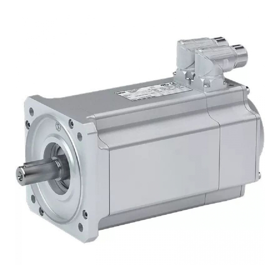
Synchronous servo motor
Hide thumbs
Also See for m850:
- Project planning (64 pages) ,
- Mounting and switch-on instructions (60 pages) ,
- Manual (160 pages)
Table of Contents
Advertisement
Quick Links
Advertisement
Table of Contents

Subscribe to Our Youtube Channel
Related Manuals for Lenze m850


Summary of Contents for Lenze m850
- Page 1 Project planning EN Servo motors m850 synchronous servo motor...
-
Page 3: Table Of Contents
Inhalt Inhalt About this document Document description Further documents Notations and conventions Product information Product description Identification of the products Features The modular system Information on project planning Safety instructions Basic safety instructions Application as directed Foreseeable misuse Residual hazards Drive dimensioning Final configuration Environmental conditions... - Page 4 Inhalt Product extensions Motor connection Connection via ICN connector Brakes Spring-applied brakes Feedback Resolver Absolute value encoder Temperature monitoring Thermal detectors PT1000 Product codes Appendix Good to know Approvals/directives Operating modes of the motor Enclosures...
-
Page 5: About This Document
Please observe the notes in the following chapters! ▶ Safety instructions ^ 12 ▶ Information on mechanical installation ^ 19 ▶ Information on electrical installation ^ 20 Further documents Information and tools with regard to the Lenze products can be found on the Internet: http://www.lenze.com à Download... -
Page 6: Notations And Conventions
About this document Notations and conventions Notations and conventions This document uses the following conventions to distinguish different types of information: Numeric notation Decimal separator Point The decimal point is always used. Example: 1 234.56 Warning UL warning Are used in English and French. UR warning Text Programs... -
Page 7: Product Information
Identification of the products Product information Product description m850 - the servo motor for a medium dynamic performance in compact design. The compact synchronous servo motor for applications in the fields of positioning, robotics, and packaging technology as well as for handling systems. -
Page 8: Features
Product information Features Features Motor connection Output flange Cooling Output shaft Feedback Spring-applied brake Temperature monitoring... -
Page 9: The Modular System
Product information The modular system The modular system Values printed in bold are standard designs. Values that are not printed in bold are potential extensions, some of them including a surcharge. Motor m850-S120/S3960 m850-S120/M3960 m850-S120/L3960 Technical data Rated power Rated torque Max. - Page 10 Product information The modular system Motor m850-S190/S3000 m850-S190/M3000 m850-S190/L2520 Technical data Rated power Rated torque Max. torque 71.0 Rated speed 3000 3000 2520 Colour Unpainted Surface and corrosion protection (called Without OKS) Different types of OKS Output shaft Solid shaft without keyway...
-
Page 11: Information On Project Planning
With the Drive Solution Designer you can carry out the drive dimensioning process quickly and with top quality. The software contains profound and proven expertise with regard to drive applications and mechatronic drive components. Please refer to your competent Lenze sales company. -
Page 12: Safety Instructions
The procedural notes and circuit details described in this document are only proposals. It is up to the user to check whether they can be adapted to the particular applications. Lenze does not take any responsibility for the suitability of the procedures and circuit proposals descri- bed. -
Page 13: Residual Hazards
Information on project planning Safety instructions Residual hazards Residual hazards Even if notes given are taken into consideration and protective measures are implemented, the occurrence of residual risks cannot be fully prevented. The user must take the residual hazards mentioned into consideration in the risk assessment for his/her machine/system. -
Page 14: Drive Dimensioning
The motor is thermally dimensioned on the basis of the mean speed and the effective torque. The mean speed of the drive should not exceed the values specified. If dimensioning processes are complex or reach limit loads, please refer to your Lenze branch office Operation chart S1 operation... - Page 15 Information on project planning Drive dimensioning Check operating conditions Check Approvals Conformity declarations Supply voltage Enclosure Ambient temperature Surface protection 4Conformities/approvals ^ 22 4Environmental conditions ^ 18 Define required input variables Necessary input variables Note Symbol Unit Mean speed utilisation Relating to the load speed n Ambient temperature °C...
- Page 16 Information on project planning Drive dimensioning Determine product on the basis of the forces Transmission element Gear wheels Sprockets Toothed belt pulleys Narrow V-belt ( depending on the pre- ( depending on the loading) preloading) ≥ 17 teeth = 1.0 ≥...
- Page 17 Information on project planning Drive dimensioning Speed profiles Temporal load characteristic for the individual time segments z Total time Individual time Load speed Load speed var- Steady-state Torque Acceleration tor- Moment of iner- segments iation load torque Δt Δ n kgcm Calculation Symbol...
-
Page 18: Final Configuration
Information on project planning Final configuration Environmental conditions Final configuration Check Connection dimensions Output shaft Output flange Product extensions Brake Feedback More information about the final configuration: 4The modular system 4Product extensions ^ 42 Environmental conditions Surface and corrosion protection (called OKS) Depending on the ambient conditions, the surface and corrosion protection system (called OKS) offers tailor-made solutions for optimum protection. -
Page 19: Information On Mechanical Installation
^ 18 Ambient media − especially chemically aggressive ones − may damage shaft sealing rings, • lacquers and plastics. If required, contact your responsible Lenze subsidiary. NOTICE Bearing damage caused by unbalance! Shafts with keyway are balanced with a half featherkey! ▶... -
Page 20: Information On Electrical Installation
The notes for the electrical connection can be found in in the terminal box (if motors with a terminal box are used). the connection plan (if motors with connectors are used). EMC-compliant wiring The EMC-compliant wiring is described in detail in the documentation of the Lenze inverters. -
Page 21: Technical Data
4 kHz. In the case of other operating conditions, the achievable values can differ from those name. In the case of extreme operating conditions, please ask the Lenze sales company that is responsible for you.. -
Page 22: Standards And Operating Conditions
Eurasian conformity: electromagnetic compatibility of technical means Approval cULus UL 1004-1 for USA and Canada (requirements of the CSA 22.2 No.100) UL 1004-6 Servo motor, Lenze file no. E210321 Protection of persons and device protection Enclosure IP54 EN 60034-5 Self-ventilated IP65... -
Page 23: Radial Forces And Axial Forces
Depending on the ambient temperatures, they are additionally limited by the grease lifetime. 4Rated data ^ 25 Application of forces Application of force at l/2 Bearing service life L Motor m850-S120/S3960 m850-S140/S3240 m850-S190/S3000 m850-S120/M3960 m850-S140/M3240 m850-S190/M3000 m850-S120/L3960 m850-S140/L3240 m850-S190/L2520... - Page 24 Technical data Radial forces and axial forces Application of force at l Bearing service life L Motor m850-S120/S3960 m850-S140/S3240 m850-S190/S3000 m850-S120/M3960 m850-S140/M3240 m850-S190/M3000 m850-S120/L3960 m850-S140/L3240 m850-S190/L2520 5000 h Radial force 1030 2170 Axial tensile force -800 -1080 -1290 ax, -...
-
Page 25: Rated Data
Technical data Rated data Inverter mains connection 400 V, Self-ventilated Rated data Inverter mains connection 400 V, Self-ventilated Product name m850-S120/S3960 m850-S120/M3960 m850-S120/L3960 Standstill torque 6.50 11.0 15.0 Rated torque 4.80 7.40 9.00 Max. torque 14.5 29.0 44.0 Rated speed 3960 3960 3960 Max. - Page 26 Technical data Rated data Inverter mains connection 400 V, Self-ventilated Product name m850-S190/S3000 m850-S190/M3000 m850-S190/L2520 Standstill torque 27.0 46.0 67.0 Rated torque 16.0 24.0 35.0 Max. torque 71.0 Rated speed 3000 3000 2520 Max. speed 4500 4500 4500 Rated power 5.00 7.50...
-
Page 27: Selection Tables
Due to a derating of the inverter output current to the derating speed, for some inverters the attaina- ble max. standstill torque is smaller than the max. speed when the value of 5 Hz is not reached. Derating speed Motor Derating speed m850-S120/S3960 m850-S120/M3960 m850-S120/L3960 m850-S140/S3240 m850-S140/M3240 m850-S140/L3240 m850-S190/S3000... - Page 28 The data apply to an inverter mains voltage of 3x 400 V and an inverter switch- ing frequency of 8 kHz. Motor Inverter E84AVTC□ 1524 2224 3024 4024 5524 7524 1134 1534 1834 2234 3034 3734 4534 m850-S120/S3960 Rated torque rated Standstill torque Max. standstill torque 11.6 14.1...
- Page 29 Technical data Selection tables Motor Inverter E84AVTC□ 1524 2224 3024 4024 5524 7524 1134 1534 1834 2234 3034 3734 4534 m850-S190/S3000 Rated torque 14.8 16.0 16.0 16.0 16.0 16.0 16.0 rated Standstill torque 16.0 21.9 27.0 27.0 27.0 27.0 27.0 Max.
- Page 30 The data apply to an inverter mains voltage of 3x 400 V and an inverter switch- ing frequency of 4 kHz. Motor Inverter E70ACMS□ 0104 0204 0324 0484 0644 m850-S120/S3960 Rated torque rated Standstill torque Max. standstill torque 10.8 14.5 0,max Max. torque 10.8 14.5...
- Page 31 Technical data Selection tables Motor Inverter E70ACMS□ 0104 0204 0324 0484 0644 m850-S190/S3000 Rated torque 15.5 16.0 16.0 16.0 rated Standstill torque 16.9 27.0 27.0 27.0 Max. standstill torque 32.8 47.8 62.5 71.0 0,max Max. torque 32.8 47.8 62.5 71.0...
- Page 32 The data apply to an inverter mains voltage of 3x 400 V and an inverter switch- ing frequency of 4 kHz. Motor Inverter E94A□□ E0044 E0074 E0094 E0134 E0174 E0244 E0324 E0474 E0594 m850-S120/S3960 Rated torque rated Standstill torque Max. standstill torque 14.5 14.5 0,max Max. torque 14.5 14.5 Transition speed 2599 2599...
- Page 33 Technical data Selection tables Motor Inverter E94A□□ E0044 E0074 E0094 E0134 E0174 E0244 E0324 E0474 E0594 m850-S190/S3000 Rated torque 13.7 16.0 16.0 16.0 16.0 16.0 rated Standstill torque 14.9 19.7 27.0 27.0 27.0 27.0 Max. standstill torque 34.2 43.2 55.0 63.6...
-
Page 34: Torque Characteristics
Technical data Torque characteristics Torque characteristics The data apply to an inverter mains voltage of 3 x 400 V. m850-S120/S3960 = 4 V = 36 V = 2x I 500 1000 1500 2000 2500 3000 3500 4000 4500 5000 5500 6000... - Page 35 Technical data Torque characteristics m850-S120/L3960 = 4 V = 36 V = 3x I = 2x I 500 1000 1500 2000 2500 3000 3500 4000 4500 5000 5500 6000 r/min m850-S140/S3240 = 4 V = 36 V = 2x I...
- Page 36 Technical data Torque characteristics m850-S140/M3240 = 4 V = 36 V = 3x I = 2x I 1000 1500 2000 2500 3000 3500 4000 4500 5000 r/min m850-S140/L3240 = 4 V = 36 V = 3x I = 2x I...
- Page 37 Technical data Torque characteristics m850-S190/S3000 = 4 V = 36 V = 3x I = 2x I 1000 1500 2000 2500 3000 3500 4000 r/min m850-S190/M3000 = 4 V = 36 V = 3x I = 2x I 1000 1500...
- Page 38 Technical data Torque characteristics m850-S190/L2520 = 4 V = 36 V = 3x I = 2x I 1000 1500 2000 2500 3000 3500 4000 r/min...
-
Page 39: Dimensions
Technical data Dimensions Basic dimensions Dimensions Basic dimensions Self-ventilated motors m850-S120 Output flange FF130 Motor m850-S120/S3960 m850-S120/M3960 m850-S120/L3960 Total length without brake Total length with brake Motor/connection distance... - Page 40 Technical data Dimensions Basic dimensions m850-S140 Output flange FF165 Motor m850-S140/S3240 m850-S140/M3240 m850-S140/L3240 Total length without brake Total length with brake Motor/connection distance...
- Page 41 Technical data Dimensions Basic dimensions m850-S190 Output flange FF215 Motor m850-S190/S3000 m850-S190/M3000 m850-S190/L2520 Total length without brake Total length with brake Motor/connection distance...
-
Page 42: Product Extensions
In order to provide for a quick and error-free connection of Lenze motors to Lenze inverters, we recommend using prefabricated Lenze system cables. In this way, proper functioning and the compliance with statutory provisions such as EMC, UL, etc. - Page 43 Product extensions Motor connection Connection via ICN connector Power and brake connection For motor: m850-S120/S3960 m850-S140/S3240 m850-S190/S3000 m850-S120/M3960 m850-S140/M3240 m850-S120/L3960 ICN-M23 connector assignment Contact Name Meaning Holding brake + Holding brake - PE conductor Power phase U Power phase V...
- Page 44 Product extensions Motor connection Connection via ICN connector ICN-M23 connector assignment: incremental and SinCos absolute value encoder Hiperface Contact Name Meaning Track B / + SIN Code 20° A¯ Track A inverse / - COS Track A / + COS + UB Supply + Mass...
- Page 45 Motor plug connection assignment NOTICE When making your selection, the motor data and permissible currents of the cables according to the system cable system manual must be observed. Power terminal connectors Motor code m850-S120/S3960 m850-S120/M3960 m850-S120/L3960 Plug ICN-M23 Motor cable 1.0/1.5/2.5...
-
Page 46: Brakes
If long motor supply cables are used, pay attention to the ohmic voltage drop along the cable and compensate for it with a higher voltage at the input end of the cable. The following applies to Lenze system cables: Resulting supply voltage U[V] U [V] 0.08... - Page 47 Product extensions Brakes To simplify matters, the friction energy per switching cycle can be calculated using the formula below and must not exceed the limit value for emergency stops, which depends on the switching rate: Friction energy Total mass inertia (motor + load) æ...
-
Page 48: Spring-Applied Brakes
Requirements with regard to the DC 24 V brake: smoothed DC voltage, ripple ≤ 1 %. Maximum switching energy for each emergency stop with n= 3000 rpm for a maximum of 3-6 emergency stops per hour. Motor m850-S120/S3960 m850-S120/M3960 m850-S120/L3960 Supply voltage range 21.6 ... - Page 49 Product extensions Brakes Spring-applied brakes Motor m850-S190/S3000 m850-S190/M3000 m850-S190/L2520 Supply voltage range 21.6 ... 25.2 in,DC Rated voltage rated,DC Rated torque At 20 °C rated At 120 °C rated Output current rated Engagement time Disengagement time Maximum switching energy 5700 Mass 6.70...
-
Page 50: Feedback
Servo motors can perform speed-dependent safety functions for safe speed and / or safe rela- tive position monitoring in a drive system by Lenze inverters or Controllers. In case of inver- ters, these functions are implemented by integrable safety modules and in case of Controllers by the additionally required Safety Controller. -
Page 51: Resolver
Product extensions Feedback Resolver Resolver The stator-supplied, 2-pole resolver with two stator windings shifted by 90 degrees and a rotor winding with a transformer winding can record both the speed and the rotor position, just like a single-turn absolute value encoder. The rotor position can be determined within one mechanical motor revolution after a voltage failure. -
Page 52: Absolute Value Encoder
Product extensions Feedback Absolute value encoder Absolute value encoder Absolute value encoders can detect the speed, the rotor position, and the machine position with a very high resolution. They are used for the positioning of dynamic applications and do not require homing. Feedback type SinCos absolute value Feedback... -
Page 53: Temperature Monitoring
Product extensions Temperature monitoring Thermal detectors PT1000 Temperature monitoring Thermal detectors PT1000 The thermal sensors used continuously monitor the motor temperature. The temperature information is transferred to the inverter using the system cable of the feedback system. This is not a full motor protection! The motors are monitored via three thermal sensors connected in series (1x PT1000 + 2x PTC 150 °C ). -
Page 54: Product Codes
30 x 100 rpm 32 x 100 rpm 40 x 100 rpm Enclosure IP5x IP6x Cooling No cooling Brake attachment No brake Spring-applied brake Permanent magnet brake Encoder mounting Resolver Absolute value encoder Product approval CE; cULus Manufacturer Lenze Internal key... -
Page 55: Appendix
Appendix Approvals/directives Appendix Good to know Approvals/directives China Compulsory Certification documents the compliance with the legal product safety requirements of the PR of China - GB standards. CSA certificate, tested according to US and Canada standards Communauté Européenne documents the declaration of the manufacturer that EC Directives are complied with. China Energy Label documents the compliance with the legal energy efficiency requirements for motors, tested according to PR of China standards Canadian Standards Association... -
Page 56: Operating Modes Of The Motor
Appendix Good to know Operating modes of the motor Operating modes of the motor Operating modes S1 ... S10 as specified by EN 60034-1 describe the basic stress of an electrical machine. In continuous operation a motor reaches its permissible temperature limit if it outputs the rated power dimensioned for continuous operation. -
Page 57: Enclosures
Appendix Good to know Enclosures Enclosures The degree of protection indicates the suitability of a motor for specific ambient conditions with regard to humidity as well as the protection against contact and the ingress of foreign particles. The degrees of protection are classified by EN 60529. The first code number after the code letters IP indicates the protection against the ingress of foreign particles and dust.The second code number refers to the protection against the ingress of humidity. - Page 60 © 11/2017 | 13545545 | 2.0 Ö Lenze Automation GmbH Postfach 10 13 52, D-31763 Hameln Hans-Lenze-Str. 1, D-31855 Aerzen Germany HR Hannover B 205381 +49 5154 82-0 Ü Ø +49 5154 82-2800 Ù lenze@lenze.com Ú www.lenze.com Û Lenze Service GmbH Breslauer Straße 3, D-32699 Extertal...
Need help?
Do you have a question about the m850 and is the answer not in the manual?
Questions and answers