Lenze ECS series Operating Instructions Manual
Ecsee series;
ecsde series;
ecsce series
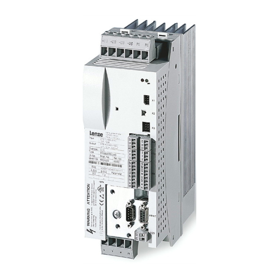
power supply module
Hide thumbs
Also See for ECS series:
- Operating instructions manual (484 pages) ,
- Mounting instructions (200 pages) ,
- Operating instructions manual (40 pages)

Related Manuals for Lenze ECS series


Summary of Contents for Lenze ECS series
- Page 1 EDBCSXE040 .RVU Operating Instructions ECSEExxx / ECSDExxx / ECSCExxx Power supply module...
- Page 2 0Fig. 0Tab. 0 © 2015 Lenze Drive Systems GmbH, Hans−Lenze−Straße 1, 31855 Aerzen No part of this documentation may be reproduced or made accessible to third parties without written consent by Lenze Drive Sy- stems GmbH. All information given in this documentation has been selected carefully and complies with the hardware and software described.
- Page 3 ECSEE_002A EDBCSXE040 EN 8.0...
- Page 4 Scope of supply Position Description Quantity ECSLE... power supply module Accessory kit with fixings according to the design (L): "E" − panel−mounted device "D" − push−through technique "C" − cold−plate technique Mounting Instructions Drilling jig Note! The ECSZE000X0B connector set must be ordered separately. Connections and interfaces Position Description...
-
Page 5: Table Of Contents
............General safety and application notes for Lenze power supply modules . - Page 6 Contents Power terminals ............5.3.1 Mains connection .
- Page 7 Contents Executing a reset node ..........Assignment of the control word .
- Page 8 Contents Appendix ..............12.1 Codes .
-
Page 9: Preface And General Information
Preface and general information About these Operating Instructions Preface and general information About these Operating Instructions These Operating Instructions help you with the connection and commissioning of the ECSxE series power supply modules. They contain safety instructions which must be observed! All persons working on and with ECSxE series power supply modules must have the Operating Instructions available and must observe the information and notes relevant for their work. -
Page 10: Terminology Used
Voltage supply of the control card, voltage range 20 ... 30 V DC (±0 V) Low−voltage supply Automation InterFace System bus (CAN) A Lenze standard bus system based on CANopen for communication with a higher−level host system (PLC) or further controllers. parameter setting and diagnostics. MotionBus (CAN) The "MotionBus (CAN)"... -
Page 11: Properties Of The Ecsxe Power Supply Module
EtherCAT connection to the EMF2192IB communication module via the automation ƒ interface (AIF) Commissioning, parameter setting and diagnostics with the Lenze parameter ƒ setting and operating program "Global Drive Control" (GDC) or the XT EMZ9371BC keypad EDBCSXE040 EN 8.0... -
Page 12: Scope Of Supply
Shield mounting ECSZS000X0B001 (EMC accessories) ƒ Components for operation and communication ƒ Brake resistors ƒ Mains fuses ƒ Mains chokes ƒ RFI filters ƒ Tip! Information and tools concerning the Lenze products can be found in the download area at www.lenze.com EDBCSXE040 EN 8.0... -
Page 13: Legal Regulations
Instructions. The specifications, processes, and circuitry described in these Instructions are for guidance only and must be adapted to your own specific application. Lenze does not take responsibility for the suitability of the process and circuit proposals. -
Page 14: Safety Instructions
– The procedural notes and circuit details described in this documentation are only proposals. It is up to the user to check whether they can be transferred to the particular applications. Lenze Drives GmbH does not accept any liability for the suitability of the procedures and circuit proposals described. - Page 15 Safety instructions General safety and application notes for Lenze power supply modules Application as directed Power supply modules are components which are designed for installation in electrical systems or machinery. They are not to be used as domestic appliances, but only for industrial purposes according to EN 61000−3−2.
- Page 16 Safety instructions General safety and application notes for Lenze power supply modules Electrical connection When working on live power supply modules, applicable national regulations (e.g. VBG 4) must be observed. The electrical installation must be carried out according to the appropriate regulations (e.g.
-
Page 17: Residual Hazards
Safety instructions Residual hazards Residual hazards Protection of persons Before working on the power supply module, check that no voltage is applied to the ƒ power terminals, because – the power terminals +UG, −UG, BR0 and BR1 remain live for at least 3 minutes after mains disconnection. -
Page 18: Safety Instructions For The Installation According To Ul/Csa
Safety instructions Safety instructions for the installation according to UL/CSA Safety instructions for the installation according to UL/CSA Original − English Warnings! General markings: Use 60/75 °C or 75 °C copper wire only. ƒ Maximum ambient temperature 55 °C, with reduced output current. ƒ... - Page 19 Safety instructions Safety instructions for the installation according to UL/CSA Original − French Warnings! Marquages d’ordre général : Utiliser exclusivement des conducteurs en cuivre 60/75 °C ou 75 °C. ƒ Température ambiante maximale de 55 °C, avec courant de sortie réduit. ƒ...
-
Page 20: Notes Used
Safety instructions Notes used Notes used The following pictographs and signal words are used in this documentation to indicate dangers and important information: Safety instructions Structure of safety instructions: Danger! (characterises the type and severity of danger) Note (describes the danger and gives information about how to prevent dangerous situations) Pictograph and signal word Meaning... -
Page 21: Technical Data
Technical data General data and operating conditions Technical data General data and operating conditions Standards and operating conditions Conformity Low−Voltage Directive (2006/95/EC) On safety of low voltage equipment TP TC 004/2011 Eurasian Conformity (TR CU 004/2011) TR CU: Technical Regulation of Customs Union Electromagnetic compatibility of technical means TP TC 020/2011 Eurasian Conformity... - Page 22 Technical data General data and operating conditions General electrical data Compliance with the requirements acc. to EN 61800−3 Noise emission Compliance with the limit class C2 according to EN 61800−3(achieved with a collective filter typical for the application) Noise immunity Requirements acc.
-
Page 23: Rated Data
Technical data Rated data Rated data Rated data Type ECSxE012 ECSxE020 ECSxE040 Mains voltage 3 x 200 −10 % ... 3 x 480 +10 % mains Rated mains voltage 3 x 400 V mains rated Mains frequency [Hz] 45 ... 66 mains Rated mains current 15.9... -
Page 24: External Brake Resistors
Technical data External brake resistors External brake resistors Assignment of external brake resistors Power supply module (standard variants) Brake resistor ECSEE... ECSDE... ECSCE... [kW] ERBM039R120W 0.12 ERBM020R150W 0.15 ERBD047R01K2 1.20 ERBD022R03K0 3.00 ERBS039R01K6 1.64 ERBS020R03K2 3.20 Continuous power Brake resistors of type ERBM... Brake resistors with specifically adapted pulse capability in IP50 design Rated data Type... - Page 25 Technical data External brake resistors Brake resistors of type ERBS... Brake resistors with an increased power loss in IP65 design (NEMA 250 type 4x) Rated data Type Brake resistor ERBS039R01K6 ERBS020R03K2 Resistance [] Continuous power 1640 3200 Amount of heat [kWs] Max.
-
Page 26: Mechanical Installation
– Ensure unimpeded ventilation of cooling air and outlet of exhaust air. – Several modules of the ECS series can be installed in the control cabinet next to each other without any clearance. The mounting plate of the control cabinet ƒ... -
Page 27: Mounting With Fixing Rails (Standard Installation)
Mechanical installation Mounting with fixing rails (standard installation) Dimensions Mounting with fixing rails (standard installation) 4.2.1 Dimensions Note! Mounting with ECSZS000X0B shield mounting kit: Mounting clearance below the module > 195 mm ƒ ECSXA005 Fig. 4−1 Dimensions for "panel−mounted" design Power supply module Dimensions [mm] Type... -
Page 28: Mounting With Thermal Separation (Push−Through Technique)
Mechanical installation Mounting with thermal separation (push−through technique) Mounting with thermal separation (push−through technique) For the push−through technique the rear panel of the control cabinet must be a steel plate with a thickness of at least 2 mm. The edges of the mounting cutout and the fixing holes for the wire clamps have to be slightly arched inwardly (to the ECS module). -
Page 29: Dimensions
Mechanical installation Mounting with thermal separation (push−through technique) Dimensions 4.3.1 Dimensions Note! Mounting with ECSZS000X0B shield mounting kit: Mounting clearance below the module > 195 mm ƒ ECSXA007 Fig. 4−2 Dimensions for "push−through design" Mounting cutout (a1 x b1), ^ 30 Power supply module Dimensions [mm] Type... - Page 30 Mechanical installation Mounting with thermal separation (push−through technique) Dimensions Dimensions of mounting cutout Note! Installation with shield mounting ECSZS000X0B: Clearance below the mounting cutout > 220 mm ƒ ECSXA063 Fig. 4−3 Dimensions of mounting cutout Mounting surface Mounting cutout for size 0 Mounting cutout for size 1 Power supply module Dimensions [mm]...
-
Page 31: Mounting Steps
Mechanical installation Mounting with thermal separation (push−through technique) Mounting steps 4.3.2 Mounting steps Proceed as follows to mount the power supply module: 1. Prepare the fixing holes for the clamps on the mounting surface. – Use the drilling jig for this purpose. 2. -
Page 32: Mounting In Cold−Plate Design
Mechanical installation Mounting in cold−plate design Mounting in cold−plate design The ECSCE... modules are intended for mounting in cold plate technique (e.g. on collective coolers). Requirements for collective coolers The following requirements must be met to ensure safe and reliable operation of the power supply modules: Good thermal contact with the cooler: ƒ... -
Page 33: Dimensions
Mechanical installation Mounting in cold−plate design Dimensions 4.4.1 Dimensions Note! Mounting with ECSZS000X0B shield mounting kit: Mounting clearance below the module > 195 mm ƒ ECSXA009 Fig. 4−4 Dimensions for "cold−plate design" Power supply module Dimensions [mm] Type Size ECSCE012 88.5 ECSCE020 ECSCE040... -
Page 34: Mounting Steps
Mechanical installation Mounting in cold−plate design Mounting steps 4.4.2 Mounting steps À Á Â ECSXA030 Fig. 4−5 Mounting for "cold−plate design" Proceed as follows to mount the power supply module: 1. Prepare the fixing holes on the mounting surface. – Use the drilling jig for this purpose. 2. -
Page 35: Electrical Installation
Electrical installation Installation according to EMC (installation of a CE−typical drive system) Electrical installation Installation according to EMC (installation of a CE−typical drive system) General information The electromagnetic compatibility of a machine depends on the type of installation ƒ and care taken.Especially consider the following: –... - Page 36 Electrical installation Installation according to EMC (installation of a CE−typical drive system) Assembly Connect the ECS modules, RFI filters, and mains choke to the earthed mounting ƒ plate with a surface as large as possible: – Mounting plates with conductive surfaces (zinc−coated or stainless steel) allow for permanent contact.
- Page 37 Electrical installation Installation according to EMC (installation of a CE−typical drive system) Shielding Connect the motor cable shield to the axis module ƒ – with the ECSZS000X0B shield mounting kit. – extensively to the mounting plate below the axis module. –...
-
Page 38: Drive System On The Mains
Electrical installation Drive system on the mains Electrical isolation Drive system on the mains This information applies to the ECS drive system, consisting of: ECSxE... power supply module ƒ ECSxK series capacitor module (optional) ƒ ECSxS/P/M/A series axis module ƒ Motor ƒ... -
Page 39: Supply Forms / Electrical Supply Conditions
Electrical installation Drive system on the mains Supply forms / electrical supply conditions 5.2.2 Supply forms / electrical supply conditions Stop! The power supply module may only be operated on balanced mains supplies. Operation on mains supplies with earthed phase is not permitted. The ECSxE series power supply modules are provided with an automatic detection of the mains voltage and adapt the brake chopper switch−on voltage. -
Page 40: Power Terminals
Electrical installation Power terminals Power terminals Danger! Hazardous electrical voltage The leakage current to earth (PE) is > 3.5 mA AC or > 10 mA DC. Possible consequences: Death or severe injuries when touching the device in the event of an error. ƒ... - Page 41 Electrical installation Power terminals Assignment of the plug connectors Terminal Function Electrical data Mains connection Dependent on application and type X21/L1 Mains phase L1 0 ... 480 V X21/L2 Mains phase L2 up to 31.3 A (^ 23) X21/L3 Mains phase L3 X21/PE Connection of PE conductor DC−bus voltage connection...
-
Page 42: Mains Connection
Electrical installation Power terminals Mains connection 5.3.1 Mains connection Important notes Keep the cables between the RFI filter and the power supply module as short as ƒ possible. – Make sure that no short−circuit can occur! Mains cables and ±U cables must not contact each other. - Page 43 Electrical installation Power terminals Mains connection Fuses Use the following circuit−breakers or UL−approved fuses to protect the mains cable (see Fig. 5−2 (¶ 42)): Power supply Dimensioning according to IEC/EN Dimensioning to UL module Circuit−breaker Cable cross−section UL fuse ECSxE012 C16 A ECSxE020 C16 A...
-
Page 44: Connection To The Dc Bus (+Ug, −Ug)
5.3.2 Connection to the DC bus (+U , −U Stop! The supply of Lenze controllers of the 82xx and 93xx series is not permitted. ƒ If synchronous motors with a high centrifugal mass are used, a considerable ƒ amount of energy can be fed back into the DC bus. Please take this into account when dimensioning the brake resistor. -
Page 45: Connection Plan For Mimimum Wiring With Internal Brake Resistor
Electrical installation Power terminals Connection plan for mimimum wiring with internal brake resistor 5.3.3 Connection plan for mimimum wiring with internal brake resistor Stop! Always operate the ECS power supply modules with a brake resistor (internal/external). The ECS power supply modules in the standard built−in unit and push−through design (ECSEE / ECSDE) are provided with a device−internal brake resistor. -
Page 46: Connection Plan For Mimimum Wiring With External Brake Resistor
Electrical installation Power terminals Connection plan for mimimum wiring with external brake resistor 5.3.4 Connection plan for mimimum wiring with external brake resistor Stop! Always operate the ECS power supply modules with a brake resistor. ƒ A parallel wiring of internal and external brake resistor is not permissible! ƒ... - Page 47 Electrical installation Power terminals Connection plan for mimimum wiring with external brake resistor Wiring of external brake resistor ERBM... ERBM... ERBM... B_ext B_ext < 10 cm " " … … +UG -UG PE T1 T2 +UG -UG PE T1 T2 ECSCE...
-
Page 48: Connection Of An Ecsxk
Electrical installation Power terminals Connection of an ECSxK... capacitor module (optional) 5.3.5 Connection of an ECSxK... capacitor module (optional) The ECS capacitor modules support the DC−bus voltage for the drive system. These capacitor module types are available: ECSxK001 (705 mF, ±20 %) ƒ... -
Page 49: Control Terminals
Electrical installation Control terminals Control terminals The supply of the control electronics requires an external 24 V DC voltage at ƒ terminals X6/+24 and X6/GND. Connect the thermal detector of an external brake resistor to the terminals X6/T1 ƒ and X6/T2. If no external brake resistor is required, jumper terminals X6/T1 and X6/T2. - Page 50 (central controller enable) of the power supply module via the relay 0. – In the default Lenze setting of the ECS axis modules, DO1 is set to "ready". "Ready" is only present if a specified DC−bus voltage has been reached.
- Page 51 Electrical installation Control terminals Cable cross−sections and screw−tightening torques Cable type Wire end ferrule Cable cross−section Tightening torque Stripping length 5 mm for screw Without wire end 0.08 ... 1.5 mm connection ferrule (AWG 28 ... 16) 0.22 ... 0.25 Nm Flexible (1.95 ...
-
Page 52: Digital Inputs And Outputs
Electrical installation Control terminals Digital inputs and outputs 5.4.1 Digital inputs and outputs Stop! If an inductive load is connected to X6/DO1, a spark suppressor with a limiting function to max. 50 V ± 0 % must be provided. Power supply enable of the power supply module The X6/DI1 input serves to start the controlled charge of the DC bus by the charging ƒ... -
Page 53: Automation Interface (Aif)
Electrical installation Automation interface (AIF) Automation interface (AIF) The keypad XT or a communication module can be attached to or removed from the automation interface (X1). This is also possible during operation. The keypad XT serves to enter and visualise parameters and codes. ƒ... -
Page 54: Wiring Of System Bus (Can)
Electrical installation Wiring of system bus (CAN) Wiring of system bus (CAN) The modules of the ECS series communicate via the system bus interface (X4). ƒ set parameters and display code contents. ƒ System bus (CAN) wiring ECSxE092 Fig. 5−9... - Page 55 Electrical installation Wiring of system bus (CAN) Specification of the transmission cable We recommend the use of CAN cables in accordance with ISO 11898−2: CAN cable in accordance with ISO 11898−2 Cable type Paired with shielding 120 W (95 ... 140 W) Impedance Cable resistance/cross−section Cable length £...
- Page 56 It is not possible to use a cable length of 450 m without using a repeater. After 360 m (point 2) a repeater must be installed. Result The Lenze repeater type EMF2176IB is used (cable reduction: 30 m) Calculation of the maximum cable length: First segment: 360 m Second segment: 360 m (according to Tab.
-
Page 57: Commissioning
Commissioning Commissioning Check before switching on the power supply module for the first time: The wiring for completeness, short−circuit, and earth fault ƒ The power connection: ƒ – Mains connection via terminals L1, L2, L3 (X21) – Connection of the RFI filter / mains choke –... -
Page 58: Commissioning Steps (Overview)
Commissioning Commissioning steps (overview) Commissioning steps (overview) Start Make basic settings (^ 59) Operation via system bus (CAN) with Control via digital inputs higher−level master (^ 62) (^ 61) Digital inputs Configure system bus (CAN) Set X6/DI1, DI2 = HIGH Digital inputs Set X6/DI1, DI2 = HIGH Specify control word... -
Page 59: Basic Settings With Gdc
Commissioning Commissioning steps (overview) Basic settings with GDC 6.1.1 Basic settings with GDC Note! Follow the commissioning steps in the given order! EDBCSXE040 EN 8.0... - Page 60 Commissioning Commissioning steps (overview) Basic settings with GDC Setting Brief description Detailed information Conditions Mains is switched off. (Green LED is dark, red LED is blinking) Power supply module is inhibited. – Control bit 1 (STE_RESET) = 0 – Power supply enable input X6/DI1 = LOW For operation in an EtherCAT network: –...
-
Page 61: Operation Via System Bus (Can) With Master Control
Setting via DIP switch (S1) or C0350 Lenze setting power supply module: 32 Changes are accepted after – a "reset node" (e.g. C0358 = 1, ^ 90). – switching off and on again the low−voltage supply. -
Page 62: Control Via Digital Inputs
Commissioning Commissioning steps (overview) Control via digital inputs 6.1.3 Control via digital inputs Note! Follow the commissioning steps in the given order! Setting Brief description Detailed information ^ 59 Initial state: Basic settings completed. C0001 = 1 Set input X6/DI2 to HIGH. Output X6/DO1 is set to HIGH when the module is ready for operation. -
Page 63: Operation Via Ethercat With Master Control
Commissioning Commissioning steps (overview) Operation via EtherCAT with master control 6.1.4 Operation via EtherCAT with master control Note! Follow the commissioning steps in the given order! Setting Brief description Detailed information ^ 59 Conditions EMF2192IB EtherCAT module is plugged onto the AIF interface (X1). -
Page 64: Setting The Mains Voltage
The correct mains voltage must be set in the power supply module to ensure correct operation. The Lenze setting is the automatic adaptation of the switching thresholds for the brake chopper operation using the mains voltage measured (C0173 = 4). Optionally, also fixed values can be set. -
Page 65: Setting Chopper Operation And Short−Circuit Braking
Index: 24448 = 5F80 Activation of brake chopper IGBT/fast discharge function (short−circuit braking) ^ 65 Selection list Information (Lenze setting printed in bold) 0 Brake chopper and short−circuit braking 1 Only brake chopper 2 Only fast discharge function (short−circuit braking) 4 Without function EDBCSXE040 EN 8.0... -
Page 66: Configuring Power Supply Enable Input
Setting of power supply enable via terminal X6/DI1 Note: The parameters can only be changed if the controller is inhibited. ^ 66 Selection list Information (Lenze setting printed in bold) 0 Mains disconnection (slow discharge) 1 Mains disconnection and TRIP−RESET 2 Mains disconnection and quick discharge (short−circuit braking) - Page 67 Setting of the "STOP" keypad key function of the ECSxE power supply module Note: The parameters can only be changed if the controller is inhibited. Selection list Information (Lenze setting printed in bold) 0 No function 1 Mains disconnection (slow discharge) 2 Quick discharge (short−circuit...
-
Page 68: Operation With External Brake Resistor
Response − monitoring of internal brake resistor (OC6) Index: 23996 = 5DBC Monitoring response of the internal brake resistor (fault message OC6) ^ 102 Selection list Information (Lenze setting printed in bold) 0 TRIP 3 No response EDBCSXE040 EN 8.0... -
Page 69: After Mains Switch−On
Commissioning After mains switch−on After mains switch−on The mains voltage detection will be enabled when the low−voltage supply is switched on. The following data are continuously recorded: Mains voltage amplitude ƒ Mains phase sequence ƒ Mains frequency ƒ Balance of the mains ƒ... -
Page 70: Parameter Setting
Parameter setting General information Parameter setting General information Controllers and power supply modules can be adapted to your application by setting ƒ the parameters. A detailed description of the functions can be found in the chapter "Commissioning" (¶ 57). The parameters for the functions are stored in numbered codes: ƒ... -
Page 71: Parameter Setting With "Global Drive Control" (Gdc)
Parameter setting with "Global Drive Control" (GDC) Parameter setting with "Global Drive Control" (GDC) With the "Global Drive Control" (GDC) parameterisation and operating program, Lenze provides a plain, concise and compatible tool for the configuration of your application−specific drive task with the PC or laptop: The GDC input assistant offers a comfortable motor selection. - Page 72 Parameter setting Parameter setting with "Global Drive Control" (GDC) GDC parameter menu ECSXE466 Fig. 7−2 GDC parameter menu in case of ECSxE power supply module By double−clicking the single menu items of the GDC parameter menu the corresponding codes for setting and display of parameters are indicated. EDBCSXE040 EN 8.0...
-
Page 73: Parameter Setting With The Xt Emz9371Bc Keypad
Parameter setting Parameter setting with the XT EMZ9371BC keypad Connecting the keypad Parameter setting with the XT EMZ9371BC keypad The keypad is available as accessories. A complete description is given in the documentation on the keypad. 7.3.1 Connecting the keypad ... -
Page 74: Description Of The Display Elements
Power outputs inhibited Adjusted current limitation is exceeded in motor mode or generator mode Speed controller 1 within its limitation Drive is torque−controlled Only active for operation with Lenze devices of the 9300 series! Active fault 1 Parameter acceptance Display... -
Page 75: Description Of The Function Keys
Inhibit the controller, LED in the key lights up. Reset fault (TRIP reset): 1. Remove cause of malfunction 2. Press S 3. Press U No menu for ECSxE power supply module Only active when operating Lenze devices of the 8200 vector or 8200 motec series. EDBCSXE040 EN 8.0... -
Page 76: Changing And Saving Parameters
Parameter setting Parameter setting with the XT EMZ9371BC keypad Changing and saving parameters 7.3.4 Changing and saving parameters All parameters for the axis module/power supply module parameterisation or monitoring are stored in codes. The codes are numbered and marked with a "C" in the documentation. Some codes store the parameters in numbered "subcodes"... -
Page 77: Configuring System Bus (Can)
X4 ˘ System bus interface (CAN) ƒ – PC interface/HMI for parameter setting and diagnostics (e.g. with the Lenze parameter setting and operating program "Global Drive Control") – Interface to a decentralised I/O system The codes for configuring the system bus (CAN) can be found in the GDC parameter menu (^ 72) under system bus (CAN). -
Page 78: Setting The Can Node Address And Baud Rate
Configuring system bus (CAN) Setting the CAN node address and baud rate Settings via DIP switch Setting the CAN node address and baud rate The CAN node address and baud rate can be set via the DIP switch (S1) or via C0350/C0351. If one of the (address) switches 2 ... - Page 79 Configuring system bus (CAN) Setting the CAN node address and baud rate Settings via DIP switch Node address setting The node address is set with the switches 2 ... 7 of the DIP switch. The switches are assigned to certain valencies. The sum of the valencies make the node address to be set (see example).
-
Page 80: Settings Via Codes
S1 usually apply. The baud rate (C0351) must be set identically for all CAN bus nodes. ƒ If the Lenze setting has been loaded via C0002, ƒ – C0351 is set to 0 (500 kbit/s); – you have to reset the baud rate (C0351) and the CAN node address (C0350). - Page 81 Configuring system bus (CAN) Setting the CAN node address and baud rate Settings via codes Save changes with C0003 = 1. The settings are only accepted after carrying out one of the following actions: Renewed switch−on of the 24 V low−voltage supply ƒ...
-
Page 82: Individual Addressing
This code is not active if one of the switches 2 ... 7 of the DIP switch is set to "ON". After the setting, a reset node is required. Selection list Information (Lenze setting printed in bold) ^ 158 0 COB−ID = basic identifier + C0350 ^ 82 1 COB−ID = 384 + C0354... - Page 83 Configuring system bus (CAN) Individual addressing Display of the resulting identifiers Save changes with C0003 = 1. The settings are only accepted after carrying out one of the following actions: Renewed switch−on of the 24 V low−voltage supply ƒ Reset node via the bus system (by the network management (NMT)) ƒ...
-
Page 84: Determining The Boot−Up Master For The Drive System
Master/slave configuration for CAN bus interface X4 ^ 84 Note: After the setting, a reset node is required. Selection list Information (Lenze setting printed in bold) 0 Slave 1 Master (CAN network PDO enable) 2 Slave node guarding Save changes with C0003 = 1. -
Page 85: Setting The Mode For Process Data Transfer
Index: 24215 = 5E97 Selection of CAN PDOs/mode for the process data transfer via the system bus (CAN) ^ 85 Selection list Information (Lenze setting printed in bold) 0 No response event−controlled/cyclic without sync 1 CAN1_IN/OUT cyclic (sync−controlled) EDBCSXE040 EN 8.0... -
Page 86: Setting The Boot−Up Time/Cycle Time
After the boot−up time has elapsed, the NMT telegram for initialising the CAN network is sent by the boot−up master and the process data transfer is started. Only valid if C0352 = 1 (master). ƒ Normally the Lenze setting (3000 ms) is sufficient. ƒ State change from "Pre−operational" to "Operational" ƒ... - Page 87 Cycle time Activation delay ^ 86 Setting range (min. value | unit | max. value) 65000 Subcodes Lenze setting Information C0356/1 3000 ms CAN boot−up time Delay time after mains connection for the initialisation by the master. Only valid if C0352 = 1 (master).
-
Page 88: Node Guarding
Master/slave configuration for CAN bus interface X4 ^ 84 Note: After the setting, a reset node is required. Selection list Information (Lenze setting printed in bold) 0 Slave 1 Master (CAN network PDO enable) 2 Slave node guarding Parameter Designation... - Page 89 When C0382 = 0 or C0383 = 0, the monitoring function is not active (no node guarding fault message is enabled). Only relevant if C0352 = 2. ^ 88 Selection list Information (Lenze setting printed in bold) 0 TRIP 1 Message 2 Warning 3 Off EDBCSXE040 EN 8.0...
-
Page 90: Executing A Reset Node
Designation Data type: INTEGER_32 C0358 CAN reset node Index: 24217 = 5E99 Make a reset node for the CAN bus node. ^ 90 Selection list Information (Lenze setting printed in bold) 0 No function 1 CAN reset EDBCSXE040 EN 8.0... -
Page 91: Assignment Of The Control Word
Configuring system bus (CAN) Assignment of the control word Assignment of the control word Control word to the power supply module (display in C0130) Byte Name Meaning Toggle bit: Bit state change as a "sign of life" of the STE_TOGGLE control Reset fault message STE_RESET... -
Page 92: Assignment Of Status Words
Configuring system bus (CAN) Assignment of status words Assignment of status words Status word 1 (display in C0131) Byte Name Meaning Power supply module not ready for operation STA1_BTB Status message: ready for operation No warning active STA1_WARNUNG At least one warning active No message active STA1_MELDUNG At least one message active... -
Page 93: Diagnostics Codes
Configuring system bus (CAN) Diagnostics codes CAN bus status (C0359) 8.10 Diagnostics codes 8.10.1 CAN bus status (C0359) C0359 serves to query the current CAN bus status. If the status of the system bus (CAN) is "Operational", you can use C0866 and C0868 to check the contents of the data words sent and received via CAN1_IN/OUT. -
Page 94: Diagnostics Pdo (C0390/1
Configuring system bus (CAN) Diagnostics codes Diagnostics PDO (C0390/1 ... 8) 8.10.2 Diagnostics PDO (C0390/1 ... 8) Parameter Name Data type: INTEGER_32 C0390 Configuration diagnostics PDO via CAN Index: 24185 = 5E79 Via C0390/1 ... 8 a diagnostics PDO (8 bytes) can be parameterised, which can be sent via CAN2_OUT. The 8 bytes can be assigned with variables for advanced diagnostics of the mains conditions and the internal state machine (mapping). -
Page 95: Monitoring Functions
Monitoring functions Monitoring functions Different monitoring functions (¶ 97) protect the drive system from impermissible operating conditions. If a monitoring function responds, the set fault response is triggered to protect the drive and ƒ the fault message is entered position 1 in the fault history buffer (C0168/x, in case ƒ... -
Page 96: Fault Responses
Monitoring functions Fault responses Fault responses ð Consequence Reaction Display Keypad XT Fail TRIP / Short−circuit braking TRIP TRIP active: ð The charging of the DC bus is stopped. With short−circuit braking TRIP the DC bus is quickly discharged via the brake resistor. ð... -
Page 97: Overview Of Monitoring Functions
Overview of monitoring functions Monitoring Possible responses l Lenze setting ü Setting possible Fault message Description Code TRIP Short−circui Message Warning t brake TRIP ü 0011 OC1 Short circuit in the DC bus ˘ ˘ ˘ ü 0012 OC2 Earth fault in the DC bus ˘... - Page 98 Monitoring Possible responses l Lenze setting ü Setting possible Fault message Description Code TRIP Short−circui Message Warning t brake TRIP ü 0105 H05 Internal fault (memory) ˘ ˘ ˘ ü 0106 H06 Internal fault (power section) ˘ ˘ ˘ ü...
-
Page 99: Configuring Monitoring Functions
Monitoring functions Configuring monitoring functions Mains monitoring (LP0, LP1) Configuring monitoring functions 9.3.1 Mains monitoring (LP0, LP1) Mains voltage and mains frequency (LP0) Mains voltage and mains frequency are permanently measured. The permissible ranges depend on the mains voltage set under C0173. The mains frequency must be within the range from 45 to 66 Hz. - Page 100 If an LP1 warning or LP1 message is active for the set time, an LP1−TRIP is enabled. Value < 65535 ms: LP1−TRIP Value = 65535 ms: LP1 warning/LP1 message ^ 99 Setting range Lenze setting (min. value | unit | max. value) 65535 65535 ms EDBCSXE040 EN 8.0...
-
Page 101: Voltage Supply Monitoring − Control Electronics (U15)
Monitoring functions Configuring monitoring functions Voltage supply monitoring − control electronics (U15) 9.3.2 Voltage supply monitoring − control electronics (U15) If the voltage at X6/DI1 or X6/DI3 falls below 17 V, TRIP "U15" is triggered. The fault can only be reset if U > 19 V. 9.3.3 DC bus monitoring (OU, OC1, OC2, OC3) Overvoltage in DC bus (OU) -
Page 102: Brake Resistor Monitoring (Oc6, Oh3)
= 5DBC Monitoring response of the internal brake resistor (fault message OC6) ^ 102 Selection list Information (Lenze setting printed in bold) 0 TRIP 3 No response External brake resistor (OH3) Stop! If an external brake resistor is used, the monitoring of the internal brake resistor must be deactivated (C0579 = 3). -
Page 103: Brake Chopper Igbt Monitoring (Oc4)
Monitoring functions Configuring monitoring functions Brake chopper IGBT monitoring (OC4) 9.3.7 Brake chopper IGBT monitoring (OC4) The brake chopper IGBT is monitored independently of the brake resistor (internal or external). There are two types of monitoring causing a TRIP "OC4": The voltage U is monitored by hardware. -
Page 104: Communication Monitoring (Ce1
ƒ TRIP "CE2" (CAN2_IN, reserved) or ƒ TRIP "CE3" (CAN3_IN, event−controlled/cyclic without sync) enabled. ƒ When C0357 = 0 ms (Lenze setting) this monitoring function is switched off. Parameter Designation Data type: INTEGER_32 C0357 CAN_IN monitoring times (CE1 ... CE3) - Page 105 When C0382 = 0 or C0383 = 0, the monitoring function is not active (no node guarding fault message is enabled). Only relevant if C0352 = 2. ^ 88 Selection list Information (Lenze setting printed in bold) 0 TRIP 1 Message 2 Warning 3 Off EDBCSXE040 EN 8.0...
-
Page 106: Diagnostics
Diagnostics Diagnostics with Global Drive Control (GDC) Diagnostics 10.1 Diagnostics with Global Drive Control (GDC) Different system values and fault messages can be read in the GDC parameter menu under Diagnostics via the following codes: Parameter Designation Data type: INTEGER_32 C0050 Mains voltage (V ) between phases L1−L2... - Page 107 Diagnostics Diagnostics with Global Drive Control (GDC) Parameter Designation Data type: INTEGER_32 C0061 Heatsink temperature Index: 24514 = 5FC2 Display of the heatsink temperature Display range (min. value | unit | max. value) −3276.7 °C 3276.7 Parameter Designation Data type: INTEGER_32 C0062 Interior device temperature Index: 24513...
- Page 108 Diagnostics Diagnostics with Global Drive Control (GDC) Parameter Designation Data type: INTEGER_32 C0161 Current TRIP fault Index: 24414 = 5F5E Display of the current TRIP fault (TRIP, short−circuit brake TRIP) ^ 117 Parameter Designation Data type: INTEGER_32 C0168 Fault history buffer Index: 24407 = 5F57 List of the fault messages occurred (TRIP, short circuit braking TRIP, message, warning)
-
Page 109: Advanced Diagnostics Via Diagnostics Pdo (Can2_Out)
Diagnostics Advanced diagnostics via diagnostics PDO (CAN2_OUT) 10.2 Advanced diagnostics via diagnostics PDO (CAN2_OUT) Via CAN2_OUT a diagnostics process data telegram (PDO) with display values concerning the mains conditions and the internal state machine can be sent from the power supply module. - Page 110 Diagnostics Advanced diagnostics via diagnostics PDO (CAN2_OUT) Value Description Size C0390/1 ... 8 Internal error bits: 2 bytes Bit 0 = 1: An Ixt overload has occurred. Bit 1 = 1: The internal brake resistor is overloaded. Bit 2 = 1: The external temperature contact is open. Bit 3 = 1: A short circuit of the brake IGBT has occurred.
-
Page 111: Diagnostics With The Xt Emz9371Bc Keypad
Diagnostics Diagnostics with the XT EMZ9371BC keypad 10.3 Diagnostics with the XT EMZ9371BC keypad In the "Diagnostic" menu the two submenus "Actual info" and "History" contain all codes monitoring the drive ƒ fault/error diagnosis ƒ In the operating level, more status messages are displayed. If several status messages are active, the message with the highest priority is displayed. -
Page 112: Diagnostics With Pcan−View
Diagnostics Diagnostics with PCAN−View Monitoring of telegram traffic on the CAN bus 10.4 Diagnostics with PCAN−View "PCAN−View" is the basic version of the "PCAN−Explorer" program for Windows® of PEAK System Technik GmbH. The program permits a simultaneous transmission and reception of CAN messages which can be transmitted manually and periodically. - Page 113 Diagnostics Diagnostics with PCAN−View Monitoring of telegram traffic on the CAN bus On the basis of the IDs displayed, you can assign the telegrams to the devices. If no telegrams are displayed, this may be caused by various factors: Is your Engineering PC connected to the correct CAN bus? ƒ...
-
Page 114: Setting All Can Nodes To The "Operational" Status
Diagnostics Diagnostics with PCAN−View Setting all CAN nodes to the "Operational" status 10.4.2 Setting all CAN nodes to the "Operational" status How to set all CAN nodes to the "Operational" status: 1. Create the following CAN message under "New transmit message": 2. -
Page 115: Troubleshooting And Fault Elimination
Troubleshooting and fault elimination Fault analysis Fault analysis via the LED display Troubleshooting and fault elimination Failures can be quickly detected and classified by means of display elements or status messages via the MotionBus (CAN). Display elements and status messages provide a rough classification of the trouble. The chapter "11.2 Fault messages"... -
Page 116: Fault Analysis With The History Buffer
Troubleshooting and fault elimination Fault analysis Fault analysis with the history buffer 11.1.3 Fault analysis with the history buffer The history buffer (C0168) enables you to trace faults. The corresponding fault messages are stored in eight memory locations in the sequence of their occurrence. Structure of the history buffer The fields under "fault history"... -
Page 117: Fault Messages
Troubleshooting and fault elimination Fault messages Causes and remedies 11.2 Fault messages 11.2.1 Causes and remedies Tip! When the fault messages are retrieved via the system bus (CAN) they are displayed as a number (see column fault number ˘number" in the following table). - Page 118 Troubleshooting and fault elimination Fault messages Causes and remedies Fault message Description Description Cause Cause Remedy Remedy Display 0032 Mains phase failure No mains phase Check mains voltage 1032 (as of operating system V2.0) Mains not sinusoidal In the case of voltage dips: 2032 Voltage dips ("unstable Reduce charging current...
-
Page 119: Reset Fault Messages (Trip−Reset)
Strong interference on control Control cables must be shielded cables Ground or earth loops in wiring PE wiring 0072 PR1 Checksum error in parameter Contact Lenze set 1 0079 PR5 Internal fault (EEPROM) Contact Lenze 0095 FAN1 Fan monitoring (only for built−in... -
Page 120: Appendix
Designation Data type: INTEGER_32 C0002 Load Lenze setting Index: 24573 = 5FFD Note: The Lenze setting can only be loaded if the controller is inhibited. Selection list Information (Lenze setting printed in bold) 0 Load Lenze setting 1 Loading executed... - Page 121 Parameter Designation Data type: INTEGER_32 C0024 Service code Index: 24551 = 5FE7 Note: Only the Lenze service is allowed to make changes! Setting range Lenze setting (min. value | unit | max. value) 10000 50ms Parameter Designation Data type: INTEGER_32...
- Page 122 C0043 Reset fault message Index: 24532 = 5FD4 Reset active fault message (TRIP−RESET) ^ 119 Selection list Information (Lenze setting printed in bold) 0 TRIP−RESET / no fault 1 Fault active Parameter Designation Data type: INTEGER_32 C0050 Mains voltage (V ) between phases L1−L2...
- Page 123 Appendix Codes Parameter Designation Data type: INTEGER_32 C0061 Heatsink temperature Index: 24514 = 5FC2 Display of the heatsink temperature Display range (min. value | unit | max. value) −3276.7 °C 3276.7 Parameter Designation Data type: INTEGER_32 C0062 Interior device temperature Index: 24513 = 5FC1 Display of the interior temperature...
- Page 124 C0125 LECOM baud rate (AIF) Index: 24450 = 5F82 Baud rate for operation via AIF interface Selection list Information (Lenze setting printed in bold) 0 9600 bits/s 1 4800 bits/s 2 2400 bits/s 3 1200 bits/s 4 19200 bits/s Parameter...
- Page 125 Appendix Codes Parameter Designation Data type: UNSIGNED_16 C0131 Status word 1 "Stat1" from power supply module Index: 24444 = 5F7C Bit coded display of the status word 1 "Stat1" from the power supply module ^ 92 Display range (min. value | unit | max. value) 0x0000 0xFFFF Bits...
- Page 126 Appendix Codes Parameter Designation Data type: UNSIGNED_16 C0150 DCTRL status word 1 Index: 24425 = 5F69 Bit coded display of the internal status word 1 Display range (min. value | unit | max. value) 0x0000 0xFFFF Bits Information (read only) Bit 0 Discharge DC bus (U <...
- Page 127 Appendix Codes Parameter Designation Data type: INTEGER_32 C0161 Current TRIP fault Index: 24414 = 5F5E Display of the current TRIP fault (TRIP, short−circuit brake TRIP) ^ 117 Parameter Designation Data type: INTEGER_32 C0168 Fault history buffer Index: 24407 = 5F57 List of the fault messages occurred (TRIP, short circuit braking TRIP, message, warning) ^ 116 ^ 117...
- Page 128 = 5F52 Mains voltage selection ^ 64 Selection list Information (Lenze setting printed in bold) No response 0 Operation on 230 V mains 1 Operation on 400 V mains 2 Operation on 460 V mains 3 Operation on 480 V mains...
- Page 129 Appendix Codes Parameter Designation Data type: INTEGER_32 C0231 Hardware version Index: 24344 = 5F18 Display of the hardware version Display range (min. value | unit | max. value) 65535 Parameter Designation Data type: INTEGER_32 C0235 Device − month of manufacture Index: 24340 = 5F14 Display of the month of manufacture of the device...
- Page 130 This code is not active if one of the switches 2 ... 7 of the DIP switch is set to "ON". (^ 78) After the setting, a reset node is required. Selection list Information (Lenze setting printed in bold) 0 500 kbps 1 250 kbps 2 125 kbps...
- Page 131 This code is not active if one of the switches 2 ... 7 of the DIP switch is set to "ON". After the setting, a reset node is required. Setting range (min. value | unit | max. value) Subcodes Lenze setting Information C0354/1 ID offset for COB−ID CAN1_IN C0354/2 ID offset for COB−ID CAN1_OUT...
- Page 132 Designation Data type: INTEGER_32 C0358 CAN reset node Index: 24217 = 5E99 Make a reset node for the CAN bus node. ^ 90 Selection list Information (Lenze setting printed in bold) 0 No function 1 CAN reset EDBCSXE040 EN 8.0...
- Page 133 Index: 24215 = 5E97 Selection of CAN PDOs/mode for the process data transfer via the system bus (CAN) ^ 85 Selection list Information (Lenze setting printed in bold) 0 No response event−controlled/cyclic without sync 1 CAN1_IN/OUT cyclic (sync−controlled) Parameter Designation...
- Page 134 When C0382 = 0 or C0383 = 0, the monitoring function is not active (no node guarding fault message is enabled). Only relevant if C0352 = 2. ^ 88 Selection list Information (Lenze setting printed in bold) 0 TRIP 1 Message 2 Warning 3 Off Parameter...
- Page 135 Appendix Codes Parameter Designation Data type: INTEGER_32 C0400 A/D values Index: 24175 = 5E6F Display of the A/D values Display range (min. value | unit | max. value) −214748 214748 Subcodes Information C0400/1 Interior device temperature C0400/2 Design ID of the power section C0400/3 External low−voltage supply C0400/4...
- Page 136 Setting of power supply enable via terminal X6/DI1 Note: The parameters can only be changed if the controller is inhibited. ^ 66 Selection list Information (Lenze setting printed in bold) 0 Mains disconnection (slow discharge) 1 Mains disconnection and TRIP−RESET 2 Mains disconnection and quick discharge (short−circuit braking)
- Page 137 Response − monitoring of internal brake resistor (OC6) Index: 23996 = 5DBC Monitoring response of the internal brake resistor (fault message OC6) ^ 102 Selection list Information (Lenze setting printed in bold) 0 TRIP 3 No response Parameter Designation Data type: INTEGER_32 C0595 Response −...
-
Page 138: Table Of Attributes
The table of attributes contains information required for communicating with the ECSxE power supply module via parameters. How to read the table of attributes: Column Meaning Entry Code Name of the Lenze code Cxxxx Name Parameter short text Text Index Index under which the parameter is addressed. - Page 139 Appendix Table of attributes Code Code Designation Designation Index Data Access Data type Factor CINH ü C0054 Mains current (r.m.s. value) 24521 5FC9 INTEGER_32 10000 ü C0055 Voltage across the brake resistor 24520 5FC8 INTEGER_32 10000 ü C0057 Mains frequency 24518 5FC6 INTEGER_32...
- Page 140 Appendix Table of attributes Code Code Designation Designation Index Data Access Data type Factor CINH ü ü C0358 CAN reset node 24217 5E99 INTEGER_32 10000 ü C0359 CAN status 24216 5E98 INTEGER_32 10000 ü ü C0360 CAN PDOs/mode selection 24215 5E97 INTEGER_32 10000...
-
Page 141: General Information About The System Bus (Can)
12.3 General information about the system bus (CAN) All Lenze drive and automation systems are provided with an integrated system bus interface for networking control components on the field level. The system bus interface serves to exchange, for instance, process data and parameter values between the nodes. - Page 142 (SDO, Service Data Objects) the transmission was successful. Parameter data of Lenze devices are called codes. The parameter data channel enables access to all Lenze codes and all CANopen indexes. Parameters are set, for instance, for the initial commissioning of a plant or when material of a production machine is exchanged.
-
Page 143: Communication Phases Of The Can Network (Nmt)
Appendix General information about the system bus (CAN) Communication phases of the CAN network (NMT) 12.3.2 Communication phases of the CAN network (NMT) Regarding communication, the controller knows the following statuses: Status Description "Initialisation" After the controller is switched on, the initialisation phase is run through. During this phase, the controller is not involved in the data exchange on the bus. - Page 144 Appendix General information about the system bus (CAN) Communication phases of the CAN network (NMT) State transitions Initialisation (14) (11) Pre-Operational (10) (13) Stopped (12) Operational E82ZAFU004 Fig. 12−2 State transitions in the CAN network (NMT) State Command Network status after Effect on process or parameter data after state change transition change...
- Page 145 Appendix General information about the system bus (CAN) Communication phases of the CAN network (NMT) Network management (NMT) The telegram structure used for the network management contains the identifier and the command included in the user data which consists of the command byte and the node address.
-
Page 146: Process Data Transfer
Appendix General information about the system bus (CAN) Process data transfer 12.3.3 Process data transfer Agreements Process data telegrams between host (master) and controller (slave) are ƒ distinguished as follows with regard to their direction: – Process data telegrams to the controller –... - Page 147 Appendix General information about the system bus (CAN) Process data transfer 12.3.3.2 Structure of the process data The process data telegrams have a maximum user data length of eight bytes each. Process data input telegram (RPDO) The process data input telegram transmits control information to the controller. ƒ...
- Page 148 Appendix General information about the system bus (CAN) Process data transfer 12.3.3.3 Transfer of the process data objects Process data objects Data transmission ECSxE ECSxS/P/M/A AIF1_IN ˘ CAN1_IN cyclic (sync−controlled) cyclic (sync−controlled) CANaux1_IN ˘ AIF2_IN ˘ RPDOs CAN2_IN ˘ event−controlled/cyclic without sync (to ECS module) CANaux2_IN ˘...
- Page 149 Appendix General information about the system bus (CAN) Process data transfer 12.3.3.4 Cyclic process data objects Tx-PDO1 Rx-PDO1 ECSxS/P/M/A... ECSXA218 Fig. 12−6 Example: Cyclic process data transfer from/to master (PLC) For the quick exchange of process data from or to the master respectively one process data object for input signals (Rx−PDO1) and one process data object for output signals (Tx−PDO18 ), each with 8 bytes of user data, is provided.
- Page 150 Appendix General information about the system bus (CAN) Process data transfer Synchronisation of PDOs with sync−controlled transmission In order that the cyclic process data can be read by the controller or the controller accepts the process data, a special telegram, the CAN sync telegram, is used in addition. The CAN sync telegram is the trigger point for sending process data of the controller to the master and transferring process data from the master to the controller.
- Page 151 Appendix General information about the system bus (CAN) Process data transfer 12.3.3.5 Event−controlled process data objects The event−controlled process data objects are particularly suitable for the data exchange between controllers and for distributed terminal extensions. They can, however, also be used by a host system.
-
Page 152: Parameter Data Transfer
ECSXA220 Fig. 12−9 Parameter data channels for parameterising ECS Parameters ... are values which are stored under codes in the Lenze controllers. ƒ are set e.g. during initial commissioning or while changing materials in a machine. ƒ are transmitted with low priority. - Page 153 Appendix General information about the system bus (CAN) Parameter data transfer 12.3.4.1 User data Structure of the parameter data telegram User data (up to 8 bytes) 1. byte 2. byte 3. byte 4. byte 5. byte 6. byte 7. byte 8.
- Page 154 Data 3. The error codes are standardised acc. to DS301, V4.02. Addressing by index and subindex The parameter or Lenze code is addressed with these bytes according to the following formula: Index = 24575 − (Lenze code number) Data 1 ...
- Page 155 Appendix General information about the system bus (CAN) Parameter data transfer 12.3.4.2 Error messages User data (up to 8 bytes) 1st byte 2nd byte 3rd byte 4. byte 5. byte 6. byte 7. byte 8. byte Index Index Command Subindex Error code Low byte High byte...
- Page 156 Appendix General information about the system bus (CAN) Parameter data transfer User data Command Index Index Subindex Data 1 Data 2 Data 3 Data 4 LOW byte HIGH byte Identifier 1541 0x40 0xC2 0x5F 0x00 0x00 0x00 0x00 0x00 Telegram from controller ƒ...
- Page 157 Appendix General information about the system bus (CAN) Parameter data transfer Writing parameters The acceleration time C0012 (parameter set 1) of the controller with the node address 1 is to be changed to 20 seconds via the SDO1 (parameter data channel 1). Identifier calculation ƒ...
-
Page 158: Addressing Of The Parameter And Process Data Objects
Appendix General information about the system bus (CAN) Addressing of the parameter and process data objects 12.3.5 Addressing of the parameter and process data objects The CAN bus system is based on a message−oriented data exchange between a transmitter and many receivers. Thus, all nodes can transmit and receive messages at the same time. The identifier in the CAN telegram ˘... - Page 159 Addressing of the parameter and process data objects Assignment of the node address for the data exchange between Lenze devices If Lenze devices are assigned with node addresses in a complete ascending order, the identifiers of the event−controlled data objects (CAN2_IO/CAN3_IO) are factory−set so that the devices are able to communicate with each other.
-
Page 160: Overview Of Accessories
12.4 Overview of accessories The accessories are not included in the scope of supply. Lenze’s basic devices and accessories are carefully matched to each other. With the basic device and the accessories, all components for a complete drive system are available. The component selection must be matched to the respective application. -
Page 161: Brake Resistor
Appendix Overview of accessories System bus components PC system bus adapter Type/order number Voltage supply via DIN connection EMF2173IB Voltage supply via PS2 connection EMF2173IB−V002 Voltage supply via PS2 connection EMF2173IB−V003 (electrical isolation to CAN bus) USB system bus adapter EMF2177IB Components for digital frequency coupling Digital frequency distributor/cables... - Page 162 Appendix Overview of accessories Brake resistors of type ERBD... Brake resistors with an increased power loss in IP20 design (protection against accidental contact acc. to NEMA 250 type 1) Brake resistor Rated data Type ERBD047R01K2 ERBD022R03K0 Resistance [] Continuous power 1200 3000 Amount of heat...
-
Page 163: Mains Fuses
Appendix Overview of accessories 12.4.5 Mains fuses Mains fuses are not included in the Lenze delivery program. Use standard fuses. ƒ When using ECSxE power supply modules which are fused on the supply side the ƒ DC−bus supply need not be fused. -
Page 164: Rfi Filters
25 m each (Lenze system cable). The interference level A is observed as long as the motor cable length per axis module is 25 m at a maximum (Lenze sytem cables) and the number of the ECS axis modules is maximally 10. -
Page 165: Index
Index Index Basic settings with GDC, 59 Baud rate Accessories, 160 − setting, 79 − brake resistors, 161 via DIP switch, 79 − communication modules, 160 − system bus (CAN). Siehe baud rate − connector set, 160 Brake chopper IGBT, monitoring, 103 −... - Page 166 Index CAN bus CAN network management (NMT), 145 − assignment of the plug connectors, 54 CAN user organisation CiA, Homepage, 142 − boot−up time setting, 86 Capacitor module, 10 − control word, assignment, 91 Capacitor module ECSxK..., Connection, 48 − cyclic process data objects, synchronisation, 150 Capacitor modules, 48 −...
- Page 167 Index Configuration Controller enable, 52 − monitoring, 95 Cooling, 28 brake chopper IGBT, 103 brake resistor, 102 Current, monitoring, 103 communication, 104 Cyclic process data objects, 149 current, 103 DC bus, 101 fan, 101 heatsink temperature, 101 mains, 99 Data telegram, 141 temperature inside the device, 101 voltage supply of control electronics, 101 Data, general electrical, 22...
- Page 168 Index Drive system on the mains, 38 Error messages, 155 − operation on public supply systems, EN 61000−3−2, 39 − Causes and remedies, 117 − supply forms / electrical supply conditions, 39 − causes and remedies, 117 − configuration, 97 −...
- Page 169 Index − power terminals, DC bus connection, 41, 44 Installation, mechanical, 26 Global Drive Control (GDC) Installation, mechanical , Important notes, 26 − Diagnostics, 106 − parameter menu, 72 Insulation resistance, 22 − Parameter setting, 71 Internal brake resistor − Connection, 45 −...
- Page 170 Index Monitoring Node ID, 158 − brake chopper IGBT, 103 Node−ID, display code, 158 − brake resistor, 102 Noise emission, 22 − communication, 104 Bus−off, 104 Noise immunity, 22 cyclic node monitoring (Node Guarding), 88, 105 Notes, definition, 20 monitoring times, 104 toggle bit monitoring, 105 −...
- Page 171 − TRIP, 96 Switching thresholds, DC−bus voltage/brake resistor, 64 − warning, 96 Sync telegram, 150 Synchronisation, cyclic process data objects, 150 Safety instructions, 14 − definition, 20 − For Lenze power supply modules, 14 − layout, 20 EDBCSXE040 EN 8.0...
- Page 172 Index System bus (CAN), 141 Telegram data, display, 93 − assignment of the plug connectors, 54 Temperature, 21 − baud rate, 55, 56 Temperature inside the device, monitoring, 101 − boot−up time setting, 86 Terminal assignment, power connections, 41 − CAN bus status (C0359), 93 −...
- Page 173 Index EDBCSXE040 EN 8.0...
- Page 174 ã K Q © 07/2015 Lenze Automation GmbH Service Lenze Service GmbH Postfach 10 13 52, 31763 Hameln Breslauer Straße 3, D−32699 Extertal Hans−Lenze−Str. 1, 31855 Aerzen GERMANY Germany HR Hannover B 205381 +49 5154 82−0 008000 2446877 (24 h helpline) Ê...
Need help?
Do you have a question about the ECS series and is the answer not in the manual?
Questions and answers