Table of Contents
Advertisement
Quick Links
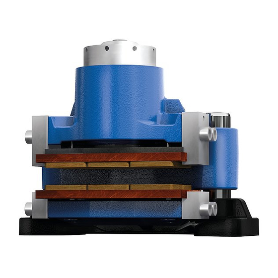
S-xx-F B-xx is a spring-actuated brake in a floating calliper design serving to ge-
nerate a brake force on a brake disk in order to decelerate a plant's movement or
stop it, respectively, or keep it at standstill.
Please observe protection
note ISO 16016.
KTR-STOP
Operating/Assembly instructions
KTR-STOP
Drawn:
2018-09-10 Shg/Wie
Verified:
2018-09-10 Shg
®
S-xx-F B-xx
®
S-xx-F B-xx
Replacing:
Replaced by:
KTR-N
44590 EN
Sheet:
1 of 26
Edition:
3
KTR-N dated 2018-02-07
Advertisement
Table of Contents

Related Manuals for KTR-Group KTR-STOP S F B Series


Summary of Contents for KTR-Group KTR-STOP S F B Series
- Page 1 KTR-N 44590 EN ® KTR-STOP S-xx-F B-xx Sheet: 1 of 26 Operating/Assembly instructions Edition: ® KTR-STOP S-xx-F B-xx S-xx-F B-xx is a spring-actuated brake in a floating calliper design serving to ge- nerate a brake force on a brake disk in order to decelerate a plant’s movement or stop it, respectively, or keep it at standstill.
-
Page 2: Table Of Contents
KTR-N 44590 EN ® KTR-STOP S-xx-F B-xx Sheet: 2 of 26 Operating/Assembly instructions Edition: The KTR brake system was designed to operate as a service brake/emergency stop brake on rotating brake disks. For any other applications please consult with KTR. Table of contents Technical data Advice... -
Page 3: Technical Data
KTR-N 44590 EN ® KTR-STOP S-xx-F B-xx Sheet: 3 of 26 Operating/Assembly instructions Edition: Technical data Illustration 1: Dimensio- nal drawing Table 1: Technical data S-xx-F B-xx Weight [kg] Approx. 85 - 90 Width of brake pad [mm] organic 28,700 Surface of each brake pad powder 26,800... - Page 4 KTR-N 44590 EN ® KTR-STOP S-xx-F B-xx Sheet: 4 of 26 Operating/Assembly instructions Edition: Technical data Table 2: Clamping force, loss of preload force, opening pressure and weight Braking torque [Nm] with Clamping force Loss of power Opening pres- Brake type brake disk Ø...
-
Page 5: Advice
KTR-N 44590 EN ® KTR-STOP S-xx-F B-xx Sheet: 5 of 26 Operating/Assembly instructions Edition: Technical data Connection dimensions of brake Illustration 3: Connection dimensions Advice 2.1 General advice Please read through these operating/assembly instructions carefully before you start up the brake. Please pay special attention to the safety instructions! The operating/assembly instructions are part of your product. -
Page 6: General Hazard Warnings
KTR-N 44590 EN ® KTR-STOP S-xx-F B-xx Sheet: 6 of 26 Operating/Assembly instructions Edition: Advice 2.3 General hazard warnings With assembly, operation and maintenance of the brake it has to be made sure that the enti- STOP re drive train is secured against accidental switch-on. You may be seriously hurt by rotating parts. -
Page 7: Assembly
KTR-N 44590 EN ® KTR-STOP S-xx-F B-xx Sheet: 7 of 26 Operating/Assembly instructions Edition: Assembly The brake is supplied in pre-assembled condition. Before assembly the brake has to be inspected for completen- ess. The brake is generally supplied with the transport lock mounted. The screw plug (component 1.20) is attached to the brake in bulk. - Page 8 KTR-N 44590 EN ® KTR-STOP S-xx-F B-xx Sheet: 8 of 26 Operating/Assembly instructions Edition: Assembly 4.1 Components of the brake Subassembly 1: Caliper with components Compo- Quantity Description nent Brake caliper Brake piston Scraper Gasket Gasket Set of disk springs Setting nut Centering pin O-ring...
- Page 9 KTR-N 44590 EN ® KTR-STOP S-xx-F B-xx Sheet: 9 of 26 Operating/Assembly instructions Edition: Assembly 4.1 Components of the brake Subassembly 3: Base plate with guide pin Compo- Quantity Description nent Base plate Guide pin Disk Cap screw DIN EN ISO 4762 - 10.9 Illustration 6: Base plate with guide pin Subassembly 4: Centering system outside Compo-...
-
Page 10: Preparation Of Assembly
KTR-N 44590 EN ® KTR-STOP S-xx-F B-xx Sheet: 10 of 26 Operating/Assembly instructions Edition: Assembly 4.1 Components of the brake Subassembly 6: Pad retraction set movable side Compo- Quantity Description nent Cap screw DIN EN ISO 4762 - 10.9 Pressure spring Illustration 9: Pad retraction set of brake caliper Subassembly 8: Pad retraction set fixed side Compo-... -
Page 11: Brake Pads
KTR-N 44590 EN ® KTR-STOP S-xx-F B-xx Sheet: 11 of 26 Operating/Assembly instructions Edition: Assembly 4.3 Brake pads KTR supplies brake pads free from asbestos and lead only. If requested, we will provide you with the corresponding certificates. The brake pads are each adapted to the application and delivered accordingly. They can be distinguished as follows: ... - Page 12 KTR-N 44590 EN ® KTR-STOP S-xx-F B-xx Sheet: 12 of 26 Operating/Assembly instructions Edition: Assembly 4.4 Assembly of the brake Insert the brake in the correct position towards the connection plate. Hand-tighten the brake via the screws for the time being. ...
-
Page 13: Setting/Resetting Of The Centering System
KTR-N 44590 EN ® KTR-STOP S-xx-F B-xx Sheet: 13 of 26 Operating/Assembly instructions Edition: Assembly 4.5 Setting/resetting of the centering system The centering systems need to be reset with initial assembly or after having replaced brake pads or single parts, respectively. This is the only way to ensure that the gap between the brake disk and the brake pad on the bottom side is set to the right value and the pad does not touch on any side. -
Page 14: Pressure Port Of A Brake
KTR-N 44590 EN ® KTR-STOP S-xx-F B-xx Sheet: 14 of 26 Operating/Assembly instructions Edition: Assembly 4.6 Pressure port of a brake Connect the pressure oil line to one of the pressure ports of the brake (see illustration 14 and 15). For that purpose remove the screw plug beforehand. -
Page 15: Pressure Port Of Several Brakes
KTR-N 44590 EN ® KTR-STOP S-xx-F B-xx Sheet: 15 of 26 Operating/Assembly instructions Edition: Assembly 4.7 Pressure port of several brakes If several brakes are assembled we recommend to connect the pressure port for each brake individually (in parallel) (see illustration 16). Please note, if several brakes are connected in a series (see illustration 17), the braking effect of all following brakes may become effective slightly delayed. -
Page 16: Start-Up Of The Brake
KTR-N 44590 EN ® KTR-STOP S-xx-F B-xx Sheet: 16 of 26 Operating/Assembly instructions Edition: Assembly 4.8 Start-up of the brake Before start-up and after each operation on the brake the hydraulic system has to be gene- rally vented. Repeat venting the brake several times a year, since any air in the hydraulic system may affect the operation of the brake and the plant. -
Page 17: Setting/Resetting Of The Brake
KTR-N 44590 EN ® KTR-STOP S-xx-F B-xx Sheet: 17 of 26 Operating/Assembly instructions Edition: Assembly 4.9 Setting/Resetting of the brake The brake needs to be set with the initial assembly or after having replaced the brake pads or single parts, respectively. Only in this way it is ensured that the brake has the clamping force specified. -
Page 18: Recommendation Of Fluids To Be Used
KTR-N 44590 EN ® KTR-STOP S-xx-F B-xx Sheet: 18 of 26 Operating/Assembly instructions Edition: Assembly 4.10 Recommendation of fluids to be used You may only use mineral hydraulic liquids meeting the specifications of DIN 51524. KTR recommends those liquids corresponding to DIN 51524-3. KTR recommends the following liquids (other manufacturers may be selected): Manufacturer Standard... -
Page 19: Disassembly Of The Brake
KTR-N 44590 EN ® KTR-STOP S-xx-F B-xx Sheet: 19 of 26 Operating/Assembly instructions Edition: Assembly 4.11 Disassembly of the brake In order to avoid any personal injuries, protect the brake by means of the assembly lock. STOP Remove the screw plug (component 1.20) or the sensor (component 9) from the setting nut (component 1.7). -
Page 20: Disposal
KTR-N 44590 EN ® KTR-STOP S-xx-F B-xx Sheet: 20 of 26 Operating/Assembly instructions Edition: Assembly 4.13 Disposal In respect of environmental protection we would ask you to dispose of the products on termination of their service life in accordance with the legal regulations and standards that apply, respectively. ... -
Page 21: Maintenance Of The Brake / Replacement Of Single Parts
KTR-N 44590 EN ® KTR-STOP S-xx-F B-xx Sheet: 21 of 26 Operating/Assembly instructions Edition: Maintenance 5.1 Replacement of brake pads Mount the pad retraction set on the movable side (component 8) by shifting the pressure spring (component 8.2) onto the pin (component 8.1). Screw the pin with the pressure spring into the brake pad against a stop. ... - Page 22 KTR-N 44590 EN ® KTR-STOP S-xx-F B-xx Sheet: 22 of 26 Operating/Assembly instructions Edition: Maintenance 5.2 Maintenance of the brake / replacement of single parts Remove the O-ring (component 1.9). Put the opening pressure (see table 2) onto the hydraulic system. ...
- Page 23 KTR-N 44590 EN ® KTR-STOP S-xx-F B-xx Sheet: 23 of 26 Operating/Assembly instructions Edition: Maintenance 5.2 Maintenance of the brake / replacement of single parts Oils and greases containing molybdenum disulphite or zinc sulphite additives must not be used. Illustration 22: Assembly of gasket and scraper Illustration 23 Inspect the surfaces of the brake piston and the hole of the housing to make sure that they are neither scratched nor damaged, since the surfaces are either ground or polished.
-
Page 24: Maintenance And Service
KTR-N 44590 EN ® KTR-STOP S-xx-F B-xx Sheet: 24 of 26 Operating/Assembly instructions Edition: Maintenance 5.2 Maintenance of the brake / replacement of single parts Shift the cap screws (component 4.1) with the pressure springs (component 4.2) into the brake caliper. Screw the hexagon nut (component 4.3) onto the cap screw (component 4.1). -
Page 25: Accessories - Sensor
KTR-N 44590 EN ® KTR-STOP S-xx-F B-xx Sheet: 25 of 26 Operating/Assembly instructions Edition: Accessories - Sensor 6.1 Technical Data „State/wear sensor“ Operation of sensor There are two micro switches in the housing of the sensor. The spacer pin activates the switches in two different positions. -
Page 26: Assembly / Start-Up
KTR-N 44590 EN ® KTR-STOP S-xx-F B-xx Sheet: 26 of 26 Operating/Assembly instructions Edition: Accessories - Sensor 6.1 Technical Data „State/wear sensor“ Technical data: Operating temperature - 40 °C to + 85 °C Max. voltage 30 V DC/AC Switching current 100 mA Protection class IP 65 (mounted)
Need help?
Do you have a question about the KTR-STOP S F B Series and is the answer not in the manual?
Questions and answers