Advertisement
Quick Links
®
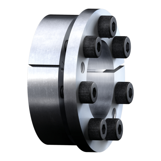
The CLAMPEX
clamping set is a frictionally engaged, detachable shaft-hub-connection for cylindrical
shafts and bores without feather key.
Table of contents
1
Technical data
2
Advice
2.1
General advice
2.2
General hazard warnings
2.3
Intended use
3
Storage, transport and packaging
3.1
Storage
3.2
Transport and packaging
4
Assembly
4.1
Components of clamping set CLAMPEX
4.2
Assembly of the clamping set
4.3
Disassembly of clamping set
5
Disposal
6
Spares inventory, customer service addresses
7
Advice regarding the use in
2014/34/EU
Please observe protection
note ISO 16016.
CLAMPEX
Operating/Assembly instructions
CLAMPEX
hazardous locations according to EU directive
Drawn:
2019-07-17 Wih/Jh
Verified:
2019-07-18 Shg
®
KTR 620
®
KTR 620
®
KTR 620
Replacing:
Replaced by:
KTR-N
40822 EN
Sheet:
1 of 11
Edition:
9
KTR-N dated 2017-05-17
2
6
6
6
7
7
7
7
7
8
8
10
10
10
11
Advertisement

Related Manuals for KTR-Group CLAMPEX 620


Summary of Contents for KTR-Group CLAMPEX 620
- Page 1 KTR-N 40822 EN ® CLAMPEX KTR 620 Sheet: 1 of 11 Operating/Assembly instructions Edition: ® CLAMPEX KTR 620 ® The CLAMPEX clamping set is a frictionally engaged, detachable shaft-hub-connection for cylindrical shafts and bores without feather key. Table of contents Technical data Advice General advice...
- Page 2 KTR-N 40822 EN ® CLAMPEX KTR 620 Sheet: 2 of 11 Operating/Assembly instructions Edition: Technical data ® Illustration 1: CLAMPEX KTR 620 Table 1: Clamping screws Surface Transmittable Dimensions Shaft DIN EN ISO 4017 - 10.9 pressure of torque [mm] ...
- Page 3 KTR-N 40822 EN ® CLAMPEX KTR 620 Sheet: 3 of 11 Operating/Assembly instructions Edition: Technical data ® Illustration 1: CLAMPEX KTR 620 Continuation: table 1 Clamping screws Surface Transmittable Dimensions Shaft DIN EN ISO 4017 - 10.9 pressure of torque [mm] ...
- Page 4 KTR-N 40822 EN ® CLAMPEX KTR 620 Sheet: 4 of 11 Operating/Assembly instructions Edition: Technical data ® Illustration 1: CLAMPEX KTR 620 Continuation: table 1 Clamping screws Surface Transmittable Dimensions Shaft DIN EN ISO 4017 - 10.9 pressure of torque [mm] ...
- Page 5 KTR-N 40822 EN ® CLAMPEX KTR 620 Sheet: 5 of 11 Operating/Assembly instructions Edition: Technical data ® Illustration 1: CLAMPEX KTR 620 Continuation: table 1 Clamping screws Surface Transmittable Dimensions Shaft DIN EN ISO 4017 - 10.9 pressure of torque or [mm] ...
-
Page 6: General Advice
KTR-N 40822 EN ® CLAMPEX KTR 620 Sheet: 6 of 11 Operating/Assembly instructions Edition: Technical data Tolerances, surfaces Tolerances for d ≤ Ø160=h6/H7 > Ø160=g6/H7 1) One proper turning process is sufficient (Rz ≤ 16 µm). 2) Maximum permissible tolerance of ®... - Page 7 KTR-N 40822 EN ® CLAMPEX KTR 620 Sheet: 7 of 11 Operating/Assembly instructions Edition: Advice 2.3 Intended use You may only assemble and disassemble the clamping set if you • have carefully read through the operating/assembly instructions and understood them •...
- Page 8 KTR-N 40822 EN ® CLAMPEX KTR 620 Sheet: 8 of 11 Operating/Assembly instructions Edition: Assembly ® 4.1 Components of clamping set CLAMPEX KTR 620 Component Quantity Description External ring (phosphated) Internal ring see table 1 Hexagon screws DIN EN ISO 4017 (phosphated) 1) External and internal rings with QPQ coating: hexagon screws DIN EN ISO 4017 with Geomet coating ®...
- Page 9 KTR-N 40822 EN ® CLAMPEX KTR 620 Sheet: 9 of 11 Operating/Assembly instructions Edition: Assembly 4.2 Assembly of the clamping set • Lightly unscrew the clamping screws and fit the clamping set KTR 620 on the hub/hollow shaft outside (see illustration 5 and 6).
- Page 10 KTR-N 40822 EN ® CLAMPEX KTR 620 Sheet: 10 of 11 Operating/Assembly instructions Edition: Assembly 4.3 Disassembly of clamping set Driving components released or falling down may cause injury to persons or damage on the STOP machine. Secure the driving components before disassembly. •...
- Page 11 KTR-N 40822 EN ® CLAMPEX KTR 620 Sheet: 11 of 11 Operating/Assembly instructions Edition: Advice regarding the use in hazardous locations according to EU directive 2014/34/EU If used in hazardous locations the type and size of clamping set (for category 3 only) has to be selected such that the difference between the peak torque of the machine including all operating parameters and the rated torque of the clamping hub at least corresponds to a safety factor of s = 2.0.
Need help?
Do you have a question about the CLAMPEX 620 and is the answer not in the manual?
Questions and answers