Table of Contents
Advertisement
Quick Links
ROTEX
Torsionally flexible jaw-type couplings
No. 001 – shaft coupling,
No. 018 – DKM,
with taper clamping sleeve
and their combinations
according to directive 2014/34/EU
for finish bored, pilot bored and
unbored couplings
Please observe protection
note ISO 16016.
ROTEX
Operating/Assembly instructions
®
Drawn:
2017-09-06 Pz/Bru
Verified:
2017-09-06 Pz
®
Type No. 001 – shaft coupling
Type No. 018 – DKM
double-cardanic coupling
Type with taper clamping sleeve
Replacing:
Replaced by:
KTR-N
40210 EN
Sheet:
1 of 22
Edition:
22
KTR-N dated 2017-01-02
Advertisement
Table of Contents

Subscribe to Our Youtube Channel
Related Manuals for KTR-Group ROTEX 001


Summary of Contents for KTR-Group ROTEX 001
- Page 1 KTR-N 40210 EN ® ROTEX Sheet: 1 of 22 Operating/Assembly instructions Edition: ® ROTEX Torsionally flexible jaw-type couplings No. 001 – shaft coupling, No. 018 – DKM, with taper clamping sleeve and their combinations according to directive 2014/34/EU for finish bored, pilot bored and unbored couplings Type No.
-
Page 2: Table Of Contents
KTR-N 40210 EN ® ROTEX Sheet: 2 of 22 Operating/Assembly instructions Edition: ® ROTEX is a torsionally flexible jaw coupling. It is able to compensate for shaft misalignment, for example caused by manufacturing inaccuracies, thermal expansion, etc. Table of contents Technical data Advice General advice... -
Page 3: Technical Data
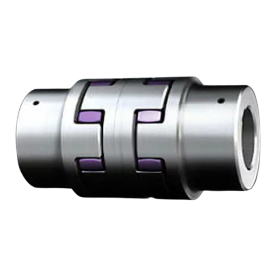
KTR-N 40210 EN ® ROTEX Sheet: 3 of 22 Operating/Assembly instructions Edition: Technical data ® ® Illustration 1: ROTEX (material: Al-D) Illustration 2: ROTEX (material: EN-GJL-250/EN-GJS-400-15) Table 1: Material Al-D Spider (component 2) Dimensions [mm] Compo Size Rated torque [Nm] General Finish bore nent... - Page 4 KTR-N 40210 EN ® ROTEX Sheet: 4 of 22 Operating/Assembly instructions Edition: Technical data ® ® Illustration 3: ROTEX (material: steel) Illustration 4: ROTEX , type DKM Table 3: Material steel Dimensions [mm] Spider (component 2) Compo Rated torque [Nm] General Size Finish bore...
-
Page 5: Advice
KTR-N 40210 EN ® ROTEX Sheet: 5 of 22 Operating/Assembly instructions Edition: Technical data Coupling design: Screwing on cam side Screwing on collar side Different combinations of types TB1 and TB2 are possible. ® Illustration 5: ROTEX , type with taper clamping sleeve Table 5: Type with taper clamping sleeve Spider (component 2) -
Page 6: Safety And Advice Symbols
KTR-N 40210 EN ® ROTEX Sheet: 6 of 22 Operating/Assembly instructions Edition: Advice 2.2 Safety and advice symbols This symbol indicates notes which may contribute to Warning of potentially explosive preventing bodily injuries or serious bodily injuries that atmospheres may result in death caused by explosion. This symbol indicates notes which may contribute to Warning of personal injury preventing bodily injuries or serious bodily injuries that... -
Page 7: Coupling Selection
KTR-N 40210 EN ® ROTEX Sheet: 7 of 22 Operating/Assembly instructions Edition: Advice 2.5 Coupling selection For a permanent and failure-free operation of the coupling it must be selected according to the selection instructions (according to DIN 740 part 2) for the particular application (see ®... -
Page 8: Assembly
KTR-N 40210 EN ® ROTEX Sheet: 8 of 22 Operating/Assembly instructions Edition: Assembly The coupling is generally supplied in individual parts. Before assembly the coupling has to be inspected for completeness. 4.1 Components of the coupling ® Components of ROTEX , shaft coupling type No. -
Page 9: Advice For Finish Bore
KTR-N 40210 EN ® ROTEX Sheet: 9 of 22 Operating/Assembly instructions Edition: Assembly 4.1 Components of the coupling Features of standard spiders 92 Shore A 95/98 Shore A 64 Shore D Spider hardness ® ® ® T-PUR T-PUR T-PUR (Shore) (orange) (yellow) (purple) -
Page 10: Assembly Of The Hubs
KTR-N 40210 EN ® ROTEX Sheet: 10 of 22 Operating/Assembly instructions Edition: Assembly 4.2 Advice for finish bore Table 7: Recommended fit pairs acc. to DIN 748/1 Bore [mm] Shaft tolerance Bore tolerance above up to (KTR standard) If a feather keyway is intended to be used in the hub, it should correspond to the tolerance ISO JS9 (KTR standard) with normal operating conditions or ISO P9 with difficult operating conditions (frequently alternating torsional direction, shock loads, etc.). -
Page 11: Assembly Of Taper Clamping Sleeve
KTR-N 40210 EN ® ROTEX Sheet: 11 of 22 Operating/Assembly instructions Edition: Assembly 4.3 Assembly of the hubs Illustration 10: Assembly of the hubs Illustration 11: Assembly of coupling 4.4 Assembly of taper clamping sleeve Assembly of taper clamping sleeve: Clean the contact surfaces of the taper clamping sleeves and of shaft and hub and afterwards apply thin fluid oil lightly (e. -
Page 12: Displacements - Alignment Of The Couplings
KTR-N 40210 EN ® ROTEX Sheet: 12 of 22 Operating/Assembly instructions Edition: Assembly 4.4 Assembly of taper clamping sleeve Disassembly of taper clamping sleeve: The taper clamping sleeve is released by removing the setscrews. Afterwards one of the setscrews used as forcing screw is screwed in the thread of the sleeve and tightened. - Page 13 KTR-N 40210 EN ® ROTEX Sheet: 13 of 22 Operating/Assembly instructions Edition: Assembly 4.5 Displacements - alignment of the couplings Examples of the displacement combinations Illustration 15: specified in illustration 15: Combinations of displacement Example 1: K = 30 % K = 70 % Example 2:...
-
Page 14: Start-Up
KTR-N 40210 EN ® ROTEX Sheet: 14 of 22 Operating/Assembly instructions Edition: Start-up Before start-up of the coupling, please inspect the tightening of the setscrews in the hubs, the alignment and the distance dimension E and adjust, if necessary, and also inspect all screw connections for the tightening torques specified, dependent on the type of coupling. -
Page 15: Breakdowns, Causes And Elimination
KTR-N 40210 EN ® ROTEX Sheet: 15 of 22 Operating/Assembly instructions Edition: Breakdowns, causes and elimination ® The below-mentioned failures can lead to a use of the ROTEX coupling other than intended. In addition to the specifications given in these operating and assembly instructions please make sure to avoid such failures. The errors listed can only be clues to search for the failures. - Page 16 KTR-N 40210 EN ® ROTEX Sheet: 16 of 22 Operating/Assembly instructions Edition: Breakdowns, causes and elimination Hazard notes for Breakdowns Causes Elimination hazardous locations 1) Set the unit out of operation Operating parameters 2) Review the operating parameters and select do not meet with the a bigger coupling (consider mounting space) performance of the...
-
Page 17: Disposal
KTR-N 40210 EN ® ROTEX Sheet: 17 of 22 Operating/Assembly instructions Edition: Disposal In respect of environmental protection we would ask you to dispose of the packaging or products on termination of their service life in accordance with the legal regulations and standards that apply, respectively. ... -
Page 18: Enclosure A
KTR-N 40210 EN ® ROTEX Sheet: 18 of 22 Operating/Assembly instructions Edition: Enclosure A Advice and instructions regarding the use in hazardous locations Type Hub design Sizes Material 38 - 90 Cast iron (GJL) 1.0, 1.1, 1.3 Standard 1a (large hub) 100 - 180 Nodular iron (GJS) clamping set 4.1, 4.2, 4.3... -
Page 19: Inspection Intervals For Couplings In
KTR-N 40210 EN ® ROTEX Sheet: 19 of 22 Operating/Assembly instructions Edition: Enclosure A Advice and instructions regarding the use in hazardous locations 10.1 Intended use in hazardous locations 2. Mining Equipment group I of category M2 (coupling is not approved for equipment group M1). ®... -
Page 20: Standard Values Of Wear
KTR-N 40210 EN ® ROTEX Sheet: 20 of 22 Operating/Assembly instructions Edition: Enclosure A Advice and instructions regarding the use in hazardous locations 10.2 Inspection intervals for couplings in hazardous locations ® ROTEX coupling Illustration 17.1: ® ROTEX elements Illustration 17.2: ®... -
Page 21: Permissible Coupling Materials In
KTR-N 40210 EN ® ROTEX Sheet: 21 of 22 Operating/Assembly instructions Edition: Enclosure A Advice and instructions regarding the use in hazardous locations 10.3 Standard values of wear Table 12: Limits of wear (friction) Limits of wear (friction) Size Size [mm] [mm] max. -
Page 22: Eu Certificate Of Conformity
KTR-N 40210 EN ® ROTEX Sheet: 22 of 22 Operating/Assembly instructions Edition: Enclosure A Advice and instructions regarding the use in hazardous locations 10.6 EU Certificate of conformity EU Certificate of conformity corresponding to EU directive 2014/34/EU dated 26 February 2014 and to the legal regulations The manufacturer - KTR Systems GmbH, D-48432 Rheine - states that the ®...
Need help?
Do you have a question about the ROTEX 001 and is the answer not in the manual?
Questions and answers