Advertisement
Quick Links
®
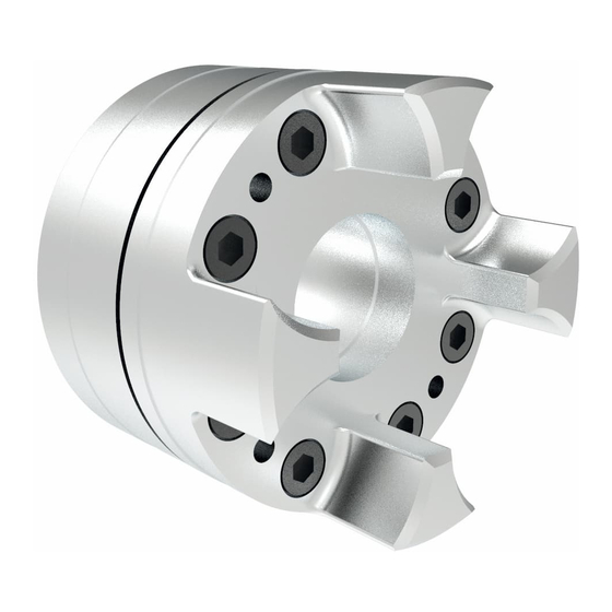
ROTEX
Torsionally flexible jaw couplings
type
shaft coupling,
clamping hubs,
Compact,
clamping ring hubs light,
clamping ring hubs,
DKM and their combinations
according to directive 2014/34/EU
Please observe protection
note ISO 16016.
ROTEX
Operating/Assembly instructions
GS
Drawn:
2020-02-10 Pz/Ht
Verified:
2020-02-10 Pz
®
GS
®
ROTEX
GS, shaft coupling
®
ROTEX
GS, clamping hubs
®
ROTEX
GS, Compact
®
ROTEX
GS, clamping ring hubs light
®
ROTEX
GS, clamping ring hubs steel
®
ROTEX
GS, clamping ring hubs
®
ROTEX
GS, DKM
Replacing:
Replaced by:
KTR-N
45510 EN
Sheet:
1 of 40
Edition:
23
KTR-N dated 2019-11-22
Advertisement

Related Manuals for KTR-Group ROTEX GS


Summary of Contents for KTR-Group ROTEX GS
- Page 1 KTR-N 45510 EN ® ROTEX Sheet: 1 of 40 Operating/Assembly instructions Edition: ® ROTEX Torsionally flexible jaw couplings ® ROTEX GS, shaft coupling type shaft coupling, clamping hubs, Compact, clamping ring hubs light, clamping ring hubs, DKM and their combinations according to directive 2014/34/EU ®...
- Page 2 KTR-N 45510 EN ® ROTEX Sheet: 2 of 40 Operating/Assembly instructions Edition: ® ROTEX GS is a plug-in shaft coupling for measuring technology and automatic control engineering. It is able to compensate for shaft misalignment, for example caused by manufacturing inaccuracies, thermal expansion, etc.
- Page 3 KTR-N 45510 EN ® ROTEX Sheet: 3 of 40 Operating/Assembly instructions Edition: Table of contents Enclosure A Advice and instructions regarding the use in potentially explosive atmospheres 10.1 Intended use in potentially explosive atmospheres 10.2 Inspection intervals for couplings in potentially explosive atmospheres 10.3 Standard values of wear 10.4...
- Page 4 KTR-N 45510 EN ® ROTEX Sheet: 4 of 40 Operating/Assembly instructions Edition: Technical data 1.1 Types of hubs Type 1.0 Type 2.0 Type 2.5 Hub with feather keyway and setscrew Clamping hub single slot without feather Clamping hub double slot without feather keyway (up to size 14 standard) keyway (from size 19 standard) Type 1.1...
- Page 5 KTR-N 45510 EN ® ROTEX Sheet: 5 of 40 Operating/Assembly instructions Edition: Technical data 1.2 Torques and finish bores Table 1: Torques of spiders Spider (component 2) Rated torque [Nm] Size 80 ShA-GS 92 ShA-GS 98 ShA-GS 64 ShD-GS 72 ShD-GS 12.0 11.0 14.5...
- Page 6 KTR-N 45510 EN ® ROTEX Sheet: 6 of 40 Operating/Assembly instructions Edition: Technical data 1.3 Coupling dimensions Standard shaft coupling ® ® Illustration 2: ROTEX Illustration 3: ROTEX (size 5 - 38) (size 42 - 90) Please refer to table 1 for torques and table 2 for finish bores. Table 3: Dimensions - Standard shaft coupling Setscrew Dimensions [mm]...
- Page 7 KTR-N 45510 EN ® ROTEX Sheet: 7 of 40 Operating/Assembly instructions Edition: Technical data 1.3 Coupling dimensions Clamping hubs ® ® Illustration 4: ROTEX Illustration 5: ROTEX hub type 2.0 (from size 5 - 14) hub type 2.5 (from size 19 - 90) ...
- Page 8 KTR-N 45510 EN ® ROTEX Sheet: 8 of 40 Operating/Assembly instructions Edition: Technical data 1.3 Coupling dimensions Table 5: Friction torques and surface pressure of clamping hubs (hub type 2.0 and 2.5) Size Transmittable friction torque T of clamping hub [Nm] Bore Ø...
- Page 9 KTR-N 45510 EN ® ROTEX Sheet: 9 of 40 Operating/Assembly instructions Edition: Technical data 1.3 Coupling dimensions Table 5 continued: Friction torques and surface pressure of clamping hubs (hub type 2.0 and 2.5) Size Transmittable friction torque T of clamping hub [Nm] Bore Ø...
- Page 10 KTR-N 45510 EN ® ROTEX Sheet: 10 of 40 Operating/Assembly instructions Edition: Technical data 1.3 Coupling dimensions Compact ® ® Illustration 6: ROTEX GS 8, 13 and 16 Compact Illustration 7: ROTEX GS 7, 9, 12, 14 and 19 Compact single slot (hub type 2.8/2.9) single slot (hub type 2.8/2.9) ®...
- Page 11 KTR-N 45510 EN ® ROTEX Sheet: 11 of 40 Operating/Assembly instructions Edition: Technical data 1.3 Coupling dimensions Table 7: Friction torques and surface pressure of type Compact (hub type 2.8 and 2.9) Size Transmittable friction torque T of clamping hub [Nm] Bore Ø...
- Page 12 KTR-N 45510 EN ® ROTEX Sheet: 12 of 40 Operating/Assembly instructions Edition: Technical data 1.3 Coupling dimensions Clamping ring hubs 6.0 light, 6.0 steel and 6.0 Extraction thread M between clamping screws. Clamping ring hub 6.0 light with block mounting (hub and clamping ring mounted as a block) 1) From Ø55 tolerance G7/m6 ®...
- Page 13 KTR-N 45510 EN ® ROTEX Sheet: 13 of 40 Operating/Assembly instructions Edition: Technical data 1.3 Coupling dimensions Table 9: Friction torque and surface pressure of clamping ring hubs 6.0 light Size Transmittable friction torque T of clamping ring hub [Nm] / surface pressure [N/mm Bore Ø...
- Page 14 KTR-N 45510 EN ® ROTEX Sheet: 14 of 40 Operating/Assembly instructions Edition: Technical data 1.3 Coupling dimensions Table 10: Friction torques and surface pressure of clamping ring hubs 6.0 steel Size Transmittable friction torque T of clamping ring hub [Nm] / surface pressure [N/mm Bore Ø...
- Page 15 KTR-N 45510 EN ® ROTEX Sheet: 15 of 40 Operating/Assembly instructions Edition: Technical data 1.3 Coupling dimensions Table 10 continued: Friction torques and surface pressure of clamping ring hubs 6.0 steel Size Transmittable friction torque T of clamping ring hub [Nm] / surface pressure [N/mm Bore Ø...
- Page 16 KTR-N 45510 EN ® ROTEX Sheet: 16 of 40 Operating/Assembly instructions Edition: Technical data 1.3 Coupling dimensions ® Illustration 10: ROTEX GS DKM Please refer to table 1 for torques and table 2 for finish bores. Table 12: Dimensions - DKM Dimensions [mm] Size M, N...
-
Page 17: General Advice
KTR-N 45510 EN ® ROTEX Sheet: 17 of 40 Operating/Assembly instructions Edition: Advice ® The ROTEX GS coupling was developed for a backlash-free power transmission and easy plug-in assembly. This backlash-free power transmission arises in the area of prestress (see illustration 11). The big concave surface contact results in a lower surface pressure on the involute tooth. -
Page 18: General Hazard Warnings
KTR-N 45510 EN ® ROTEX Sheet: 18 of 40 Operating/Assembly instructions Edition: Advice 2.2 Safety and advice symbols This symbol indicates notes which may contribute to Warning of potentially explosive preventing bodily injuries or serious bodily injuries that atmospheres may result in death caused by explosion. This symbol indicates notes which may contribute to Warning of personal injury preventing bodily injuries or serious bodily injuries that... - Page 19 KTR-N 45510 EN ® ROTEX Sheet: 19 of 40 Operating/Assembly instructions Edition: Advice 2.5 Coupling selection For a long-lasting and failure-free operation of the coupling it must be selected according to the selection instructions (following DIN 740, part 2 with specific factors) for the particular ®...
- Page 20 KTR-N 45510 EN ® ROTEX Sheet: 20 of 40 Operating/Assembly instructions Edition: Assembly The coupling is generally supplied in individual parts. Before assembly the coupling has to be inspected for completeness. 4.1 Components of the coupling Features of standard spiders Increasing hardness Spider hardness (Shore)
- Page 21 KTR-N 45510 EN ® ROTEX Sheet: 21 of 40 Operating/Assembly instructions Edition: Assembly 4.1 Components of the coupling ® Components of ROTEX GS clamping hubs, hub type 2.0, 2.1, 2.5 or 2.6 Component Quantity Description Clamping hub Spider Cap screw DIN EN ISO 4762 ®...
- Page 22 KTR-N 45510 EN ® ROTEX Sheet: 22 of 40 Operating/Assembly instructions Edition: Assembly 4.1 Components of the coupling ® Components of ROTEX GS clamping ring hubs, hub type 6.0 light, 6.0 steel or 6.0 Component Quantity Description Clamping ring Clamping ring hub Spider see table Cap screw DIN EN ISO 4762...
- Page 23 KTR-N 45510 EN ® ROTEX Sheet: 23 of 40 Operating/Assembly instructions Edition: Assembly 4.2 Advice for assembly ® Subject to its design ROTEX GS allows to axially plug in the coupling having assembled the hubs onto the shaft journal. Consequently there is no need for subsequent screwing and the respective mounting holes in the housing.
- Page 24 KTR-N 45510 EN ® ROTEX Sheet: 24 of 40 Operating/Assembly instructions Edition: Assembly 4.4 Assembly of the hubs (hub type 1.0, 1.1 and 1.2) We recommend to inspect bores, shaft, keyway and feather key for dimensional accuracy before assembly. Before starting with the assembly preserving agents have to be removed from the bores.
- Page 25 KTR-N 45510 EN ® ROTEX Sheet: 25 of 40 Operating/Assembly instructions Edition: Assembly 4.5 Assembly of the clamping hubs (hub types 2.0, 2.1, 2.5, 2.6, 2.8 and 2.9) ® The power transmission of ROTEX GS clamping hubs (hub type 2.0, 2.5 and 2.8) is frictionally engaged. With hub type 2.1, 2.6 and 2.9 a feather key additionally provides for positive locking power transmission.
- Page 26 KTR-N 45510 EN ® ROTEX Sheet: 26 of 40 Operating/Assembly instructions Edition: Assembly 4.6 Assembly of clamping ring hubs (hub type 6.0 light, 6.0 steel and 6.0) For clamping connections with hollow shafts the − required internal diameter of the hollow shaft d calculated based on the following formula: ...
- Page 27 KTR-N 45510 EN ® ROTEX Sheet: 27 of 40 Operating/Assembly instructions Edition: Assembly 4.7 Disassembly of clamping ring hubs (hub type 6.0 light, 6.0 steel and 6.0) Unscrew the clamping screws evenly one after another. During every revolution every screw may only be unscrewed by half a turn. Unscrew all clamping screws by 3 - 4 pitches.
- Page 28 KTR-N 45510 EN ® ROTEX Sheet: 28 of 40 Operating/Assembly instructions Edition: Assembly 4.8 Displacements - alignment of the couplings Angular displacements Radial displacements Axial displacements K = L +/- K [mm] = L 1max 1min Illustration 23: Displacements Examples of the displacement combinations Illustration 24: specified in illustration 24: Combinations of...
- Page 29 KTR-N 45510 EN ® ROTEX Sheet: 29 of 40 Operating/Assembly instructions Edition: Assembly 4.8 Displacements - alignment of the couplings Table 15: Displacement figures - type DKM Max. axial Max. radial displacement K Max. angular displacement K [mm] [degree] displace- Size ment K [mm]...
- Page 30 KTR-N 45510 EN ® ROTEX Sheet: 30 of 40 Operating/Assembly instructions Edition: Start-up During operation of the coupling, please pay attention to • different operating noise • vibrations occurring. If you note any irregularities with the coupling during operation, the drive unit must be switched off immediately.
- Page 31 KTR-N 45510 EN ® ROTEX Sheet: 31 of 40 Operating/Assembly instructions Edition: Breakdowns, causes and elimination Hazard notes for Breakdowns Causes potentially explosive Elimination atmospheres 1) Set the unit out of operation 2) Eliminate the reason for the misalignment Increased temperature on (e.
- Page 32 KTR-N 45510 EN ® ROTEX Sheet: 32 of 40 Operating/Assembly instructions Edition: Breakdowns, causes and elimination Hazard notes for Breakdowns Causes potentially explosive Elimination atmospheres 1) Set the unit out of operation 2) Disassemble the coupling and remove residues of the spider excessively high/low 3) Inspect coupling components and replace ambient/contact...
-
Page 33: Maintenance And Service
KTR-N 45510 EN ® ROTEX Sheet: 33 of 40 Operating/Assembly instructions Edition: Maintenance and service ® ROTEX GS is a low-maintenance coupling. We recommend to perform a visual inspection on the coupling at least once a year. Please pay special attention to the condition of the coupling spiders. •... -
Page 34: Potentially Explosive Atmospheres
KTR-N 45510 EN ® ROTEX Sheet: 34 of 40 Operating/Assembly instructions Edition: Enclosure A Advice and instructions regarding the use in potentially explosive atmospheres Applicable hub designs/types: a) Hubs that may be used in group II, category 2 and 3 : ®... - Page 35 KTR-N 45510 EN ® ROTEX Sheet: 35 of 40 Operating/Assembly instructions Edition: Enclosure A Advice and instructions regarding the use in potentially explosive atmospheres 10.1 Intended use in potentially explosive atmospheres Conditions of operation in potentially explosive atmospheres ® ROTEX GS couplings are suitable for the use according to EU directive 2014/34/EU.
- Page 36 KTR-N 45510 EN ® ROTEX Sheet: 36 of 40 Operating/Assembly instructions Edition: Enclosure A Advice and instructions regarding the use in potentially explosive atmospheres 10.2 Inspection intervals for couplings in potentially explosive atmospheres Equipment category Inspection intervals For couplings operated in zone 2 or zone 22 the inspection and maintenance intervals of the usual operating/assembly instructions for standard operation apply.
- Page 37 KTR-N 45510 EN ® ROTEX Sheet: 37 of 40 Operating/Assembly instructions Edition: Enclosure A Advice and instructions regarding the use in potentially explosive atmospheres 10.3 Standard values of wear In case of backlash > X mm, the flexible spider must be replaced. Monitoring of the general condition of the coupling can be done both at standstill and during operation.
- Page 38 KTR-N 45510 EN ® ROTEX Sheet: 38 of 40 Operating/Assembly instructions Edition: Enclosure A Advice and instructions regarding the use in potentially explosive atmospheres 10.4 marking of couplings for potentially explosive atmospheres ® The ATEX marking of the ROTEX GS coupling is applied on the outer sheath or on the front side. The flexible spider is excluded.
- Page 39 KTR-N 45510 EN ® ROTEX Sheet: 39 of 40 Operating/Assembly instructions Edition: Enclosure A Advice and instructions regarding the use in potentially explosive atmospheres 10.4 marking of couplings for potentially explosive atmospheres Deviating marking applies until 31st October 2019: Short marking: II 2GD c IIC T X/I M2 c X ...
-
Page 40: Eu Certificate Of Conformity
KTR-N 45510 EN ® ROTEX Sheet: 40 of 40 Operating/Assembly instructions Edition: Enclosure A Advice and instructions regarding the use in potentially explosive atmospheres 10.5 EU Declaration of conformity EU Certificate of conformity corresponding to EU directive 2014/34/EU dated 26 February 2014 and to the legal regulations The manufacturer - KTR Systems GmbH, D-48432 Rheine - states that the ®...
Need help?
Do you have a question about the ROTEX GS and is the answer not in the manual?
Questions and answers