Table of Contents
Advertisement
Quick Links
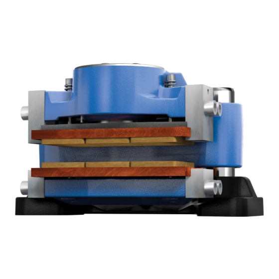
M-A-F B-xx is a brake actuated hydraulically in a floating caliper design serving
to generate a brake force on a brake disk in order to decelerate a machine's mo-
vement or stop it, respectively, or keep it at standstill.
Please observe protection
note ISO 16016.
KTR-STOP
Operating/Assembly instructions
KTR-STOP
Drawn:
2022-12-20 Ka/Wie
Verified:
2022-12-21 Ka
®
M-A-F B-xx
®
M-A-F B-xx
Replacing:
Replaced by:
KTR-N
445145 EN
Sheet:
1 of 23
Edition:
1
Advertisement
Table of Contents

Related Manuals for KTR-Group KTR-STOP M-A-F B Series


Summary of Contents for KTR-Group KTR-STOP M-A-F B Series
- Page 1 KTR-N 445145 EN ® KTR-STOP M-A-F B-xx Sheet: 1 of 23 Operating/Assembly instructions Edition: ® KTR-STOP M-A-F B-xx M-A-F B-xx is a brake actuated hydraulically in a floating caliper design serving to generate a brake force on a brake disk in order to decelerate a machine's mo- vement or stop it, respectively, or keep it at standstill.
-
Page 2: Table Of Contents
KTR-N 445145 EN ® KTR-STOP M-A-F B-xx Sheet: 2 of 23 Operating/Assembly instructions Edition: The KTR brake system was designed to operate as a service brake/emergency stop brake on rotating brake disks. For any other applications please consult with KTR. Table of contents Technical data Advice... -
Page 3: Technical Data
KTR-N 445145 EN ® KTR-STOP M-A-F B-xx Sheet: 3 of 23 Operating/Assembly instructions Edition: Technical data Illustration 1: Dimen- sional dra- wing Table 1: Technical data M-A-F B-xx Weight in kg Approx. 235 Width of brake pad in mm organic in mm 57,900 Surface of each brake pad... - Page 4 KTR-N 445145 EN ® KTR-STOP M-A-F B-xx Sheet: 4 of 23 Operating/Assembly instructions Edition: Technical data Calculation of braking force/braking torque: Braking power in kN Clamping force in kN Braking torque in kNm − Number of brakes ...
-
Page 5: Advice
KTR-N 445145 EN ® KTR-STOP M-A-F B-xx Sheet: 5 of 23 Operating/Assembly instructions Edition: Technical data Connection dimensions of brake Illustration 3: Connection dimensions Advice 2.1 General advice Read carefully through these operating/assembly instructions before you start up the brake. Please pay special attention to the safety instructions! The operating/assembly instructions are part of your product. -
Page 6: General Hazard Warnings
KTR-N 445145 EN ® KTR-STOP M-A-F B-xx Sheet: 6 of 23 Operating/Assembly instructions Edition: Advice 2.3 General hazard warnings With assembly, operation and maintenance of the brake it has to be made sure that the enti- S T O P re drive train is secured against accidental switch-on. -
Page 7: Assembly
KTR-N 445145 EN ® KTR-STOP M-A-F B-xx Sheet: 7 of 23 Operating/Assembly instructions Edition: Assembly The brake is supplied in pre-assembled condition. Before assembly the brake has to be inspected for completen- ess. 4.1 Components of the brake Components/subassemblies of brake – Type M-A-F B-xx Compo- nent/sub- Quantity... - Page 8 KTR-N 445145 EN ® KTR-STOP M-A-F B-xx Sheet: 8 of 23 Operating/Assembly instructions Edition: Assembly 4.1 Components of the brake Subassembly 3: Base plate with guide pin Compo- Quantity Description nent Base plate Guide pin Illustration 6: Base plate with guide pin Subassembly 4: Centering system Compo- Quantity...
-
Page 9: Preparation Of Assembly
KTR-N 445145 EN ® KTR-STOP M-A-F B-xx Sheet: 9 of 23 Operating/Assembly instructions Edition: Assembly 4.1 Components of the brake Subassembly 7: Pad retraction set fixed side Compo- Quantity Description nent Cap screw DIN EN ISO 7379 - 10.9 Pressure spring Sealing plug Illustration 9: Pad retraction set on fixed side 4.2 Preparation of assembly... -
Page 10: Brake Pads
KTR-N 445145 EN ® KTR-STOP M-A-F B-xx Sheet: 10 of 23 Operating/Assembly instructions Edition: Assembly 4.3 Brake pads KTR supplies brake pads free from asbestos and lead only. If requested, we will provide you with the respective certificates. The brake pads are each adapted to the application and delivered accordingly. They can be distinguished as follows: •... - Page 11 KTR-N 445145 EN ® KTR-STOP M-A-F B-xx Sheet: 11 of 23 Operating/Assembly instructions Edition: Assembly 4.4 Assembly of the brake • Mount the pad retraction set on the movable side (component 7) by shifting the pressure spring (component 7.2) onto the pin (component 7.1). Screw the hexagon screw with the pressure spring into the brake pad against a stop.
-
Page 12: Setting/Resetting Of The Centering System
KTR-N 445145 EN ® KTR-STOP M-A-F B-xx Sheet: 12 of 23 Operating/Assembly instructions Edition: Assembly 4.4 Assembly of the brake In order to avoid any contact between the brake disk and the brake resulting from thermal expansion, the distance of the brake as per table 3 needs to be observed. Make sure that the tolerances of the brake disk do not exceed the figures specified in illust- ration 3. -
Page 13: Pressure Connection Of A Brake
KTR-N 445145 EN ® KTR-STOP M-A-F B-xx Sheet: 13 of 23 Operating/Assembly instructions Edition: Assembly 4.6 Pressure connection of a brake • Connect the pressure oil line to one of the pressure connections of the brake (see illustration 13 and 14). For that purpose remove the screw plug beforehand. -
Page 14: Pressure Connection Of Several Brakes
KTR-N 445145 EN ® KTR-STOP M-A-F B-xx Sheet: 14 of 23 Operating/Assembly instructions Edition: Assembly 4.7 Pressure connection of several brakes If several brakes are assembled we recommend to connect the pressure connection for each brake individually (in parallel) (see illustration 15). Please note, if several brakes are connected in a series (see illustration 16), the braking effect of all following brakes may become effective slightly delayed. -
Page 15: Start-Up Of The Brake
KTR-N 445145 EN ® KTR-STOP M-A-F B-xx Sheet: 15 of 23 Operating/Assembly instructions Edition: Assembly 4.8 Start-up of the brake Before start-up and after each operation on the brake the hydraulic system has to be gene- rally vented. Repeat venting the brake several times a year, since any air in the hydraulic system may affect the operation of the brake and the plant. -
Page 16: Disassembly Of The Brake
KTR-N 445145 EN ® KTR-STOP M-A-F B-xx Sheet: 16 of 23 Operating/Assembly instructions Edition: Assembly 4.9 Recommendation of fluids to be used Viscosity We would recommend a viscosity range from 20 to 220 mm /s (cSt) of the hydraulic liquid with operating tempera- ture. -
Page 17: Spares Inventory, Customer Service Addresses
KTR-N 445145 EN ® KTR-STOP M-A-F B-xx Sheet: 17 of 23 Operating/Assembly instructions Edition: Assembly 4.11 Spares inventory, customer service addresses A basic requirement to ensure the readiness for use of the brake is a stock of the most important spare parts on site. - Page 18 KTR-N 445145 EN ® KTR-STOP M-A-F B-xx Sheet: 18 of 23 Operating/Assembly instructions Edition: Maintenance 5.1 Replacement of brake pads Please make sure that at least one screw plug (component 1.6) is removed when moving back the brake piston. Afterwards re-assemble the screw plug. •...
-
Page 19: Maintenance Of The Brake / Replacement Of Single Parts
KTR-N 445145 EN ® KTR-STOP M-A-F B-xx Sheet: 19 of 23 Operating/Assembly instructions Edition: Maintenance 5.2 Maintenance of the brake / replacement of single parts To ensure the full braking power, both disassembly and assembly have to be performed at the highest level of purity. - Page 20 KTR-N 445145 EN ® KTR-STOP M-A-F B-xx Sheet: 20 of 23 Operating/Assembly instructions Edition: Maintenance 5.2 Maintenance of the brake / replacement of single parts Observe the manufacturer’s instructions regarding the use of solvents. Inspect the DU bushes (component 1.2) and scrapers (component 1.13) for any kind of damage, if necessary, the compo- nents have to be replaced.
-
Page 21: Maintenance And Service
KTR-N 445145 EN ® KTR-STOP M-A-F B-xx Sheet: 21 of 23 Operating/Assembly instructions Edition: Maintenance 5.2 Maintenance of the brake / replacement of single parts • Fit the pre-assembled unit carefully on the guide pins. Make sure that the centering system (component 4) is not damaged. •... -
Page 22: Accessories - Sensor
KTR-N 445145 EN ® KTR-STOP M-A-F B-xx Sheet: 22 of 23 Operating/Assembly instructions Edition: Accessories - Sensor 6.1 Technical Data „State/wear sensor“ Operation of sensor There are two micro switches in the housing of the sensor. The spacer pin activates the switches in two different positions. -
Page 23: Assembly / Start-Up
KTR-N 445145 EN ® KTR-STOP M-A-F B-xx Sheet: 23 of 23 Operating/Assembly instructions Edition: Accessories - Sensor 6.1 Technical Data „State/wear sensor“ Technical data: Operating temperature -40 °C to +85 °C Max. voltage 30 V DC/AC Switching current 100 mA Protection class IP 65 (mounted) Width across flats...
Need help?
Do you have a question about the KTR-STOP M-A-F B Series and is the answer not in the manual?
Questions and answers