Dynamatic 4000 Instruction Sheet
Hide thumbs
Also See for 4000:
- Instruction manual (52 pages) ,
- Instruction sheet (14 pages) ,
- Instruction manual (47 pages)
Table of Contents
Advertisement
Quick Links
Instruction Sheet
IS-539-15
revised 2019
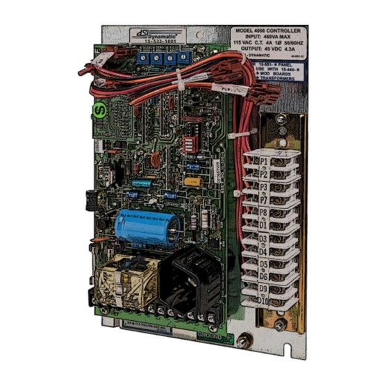
15-533-1015 Panel Mount 4000 (4.3 A Controller)
15-551-1015 Standard Enclosure 4000 (4.3 A Controller)
15-539-0015 Panel Mount 4050 (8 A Controller)
15-553-0015 Standard Enclosure 4050 (8 A Controller)
Model 4000 and 4050 with Torque Limit and Jog at Run Speed
Introduction
These instructions relate specifically to
the model 4000 and 4050 controllers
assembled for Speed Control with
Torque Limit and Jog at Run Speed
modification.
Connection
schematic
diagram,
programming, plug wiring connection,
adjustment
procedure
recommended spare parts list for these
specific assemblies are contained in
this Instruction Sheet. Any differences
between these two controllers are
clearly noted. Use Instruction Manual
IM-130006-83XX with this Instruction
Sheet
for
complete
operation
and
instructions.
Caution: Above ground electrical
potentials scan be hazardous. Always
disconnect electrical power before
working on the controller.
*Heat sink assembly, HS1, and its
wiring are only supplied on 4050
controls. The parts are mounted on the
15-530-5 main 4000 boards.
1
diagram,
switch
and
installation,
maintenance
Drive Source International/Dynamatic
7900 Durand Ave Bldg 3 Sturtevant, WI 53177
sales@dynamatic.com
800-548-2169 •
www.Dynamatic.com
Advertisement
Table of Contents

Related Manuals for Dynamatic 4000


Summary of Contents for Dynamatic 4000
-
Page 1: Introduction
15-551-1015 Standard Enclosure 4000 (4.3 A Controller) 15-539-0015 Panel Mount 4050 (8 A Controller) 15-553-0015 Standard Enclosure 4050 (8 A Controller) Model 4000 and 4050 with Torque Limit and Jog at Run Speed Introduction These instructions relate specifically to the model 4000 and 4050 controllers... -
Page 2: Table Of Contents
Connection diagram for Standard Enclosure 4000 Controller ..............3 Schematic Diagram for 4000 Controller ....................4 Connection Diagram for 4000 Panel Mount and 4050 Controllers ............5 Schematic Diagram for 4050 Controller ....................6 Low Signal Follower Modification PCB 15-444-2 ..................6 MODIFICATION PCB MOUNTING .................. -
Page 3: Connection Diagram For Standard Enclosure 4000 Controller
Connection diagram for Standard Enclosure 4000 Controller ED-58215... -
Page 4: Schematic Diagram For 4000 Controller
Schematic Diagram for 4000 Controller... -
Page 5: Connection Diagram For 4000 Panel Mount And 4050 Controllers
Connection Diagram for 4000 Panel Mount and 4050 Controllers ED-56815... -
Page 6: Schematic Diagram For 4050 Controller
Schematic Diagram for 4050 Controller Torque Limit Modification PCB 15-444-2... -
Page 7: Modification Pcb Mounting
Modification PCB Mounting If you have purchased a complete controller this section may be passed over and you may proceed to General Description. 1. Place the Main PCB in front of you with the long dimension in a horizontal position and the terminal strip to the left. -
Page 8: Trimpot Illustration
Mechanical Unit Model Numbers Velocity Damping AC/ACW/ACS/PD/VT AS/AT/AE/VT/EC Setting Fractional Hp (FHP) Fractional Hp 14/112/140 181/182/184/186 18/21/132/160/180/210 214/216/254/256 25/27/180/225/250/280 280/320/360/440 320/360/440 Mechanical Unit Model Numbers TC Adjust Setting AC/ACW/ACS/PD/VT Fractional AS/AT/AE/VT/EC Hp (FHP) FHP/181/182 184/186/214 14/18/112/132/140/180 216/254/256/280 21/160/210 320/360/440 25/24/180/225/250/280 100% 320/360/440 *Typical product number stamped on mechanical unit nameplate:... -
Page 9: Adjustment Procedure
Caution: To avoid personal injury or damage to the test equipment remove power before connecting or disconnecting test equipment. The Model 4000 and 4050 controllers contain an LED status monitor which provides a visual means of setting the maximum speed and zero adjust. This LED set up along with an alternate method is given below. -
Page 10: Max Speed/Volts R21, Alternate Methods
A trimpot illustration is provided to facilitate the setting of this control. Sufficient range has been provided for drive size from fractional through 20 hp for the 4000 controller and up to 125 hp for the 4050 controller. Set you TC control appropriately for your individual drive size as shown in Preliminary Adjustments. -
Page 11: Accel Rate R18
See Preliminary Adjustments. If instability (speed control becomes erratic) occurs at any setting increase (turn CW) slightly until the speed becomes stable. *See basic 4000/4050 manual for a more destined description of this adjustment. HI Damping R20- This pot is located on the Torque Limit modification board. It is used for applications, such as stamping presses, where the load inertia is greater than 5 to 10 times the drive inertia. -
Page 12: Torque Limit Pcb 15-444-2
c. When the clutch is being torque limited, decrease the setting of the torque damping potentiometer r18 CCW until instability (hunting develops. Then increase the setting CW until stability is attained. Recheck the Torque Limit setting as described in step 11b and readjust if necessary. -
Page 13: Renewal Parts List
Renewal Parts List for Standard 4000 & 4050 Controllers with Torque Limit and Jog at Run Speed Part Number Description Legend Model 4000 Controllers 15-530-0005 Main PCB Assembly ** 27-123-0001 Mini-Jumper 32-018-4091 Fuse, 4 Amp, 250 V FU1, 2 53-398-0001... - Page 14 Drive Source International/Dynamatic 7900 Durand Ave Bldg 3 Sturtevant, WI 53177 sales@dynamatic.com 800-548-2169 • www.Dynamatic.com...
Need help?
Do you have a question about the 4000 and is the answer not in the manual?
Questions and answers