Table of Contents
Advertisement
Quick Links
Advertisement
Table of Contents

Related Manuals for Dynamatic CES


Summary of Contents for Dynamatic CES
- Page 1 IM-110007-2019 C.E.S. Stamping Press Controller INSTRUCTION MANUAL (Revised 2019) 7900 Durand Avenue, Bldg 3 Sturtevant, WI USA 53177 Toll Free: (800) 548-2169 Phone: (262) 554-7977 - Fax: (262) 554- 7041 Email: sales@dynamatic.com Web: www.dynamatic.com...
- Page 2 Stand on an insulating pad and make it a Yellow pages under “Power Transmission Equipment”. habit to use only one hand when checking Components. Or you can call DSI/Dynamatic® at 1-800/548-2169. Always work with another person in case an emergency occurs. Disconnect power whenever possible to check IMPORTANT NOTICE controllers or to perform maintenance.
-
Page 3: Table Of Contents
SECTION 4 - START-UP AND ADJUSTMENT Power Conversion Press Speed Control Angle Measuring and Control Circuitry Start-Up Procedure Approximate Parameter Settings SECTION 5 - MAINTENANCE AND TROUBLESHOOTING Maintenance Troubleshooting Renewal Parts, and Service List of Spare Parts Common to All CES/DR Controls... -
Page 4: Section 1 - General Information
Refer to OSHA rules and regulations, paragraph 1910.219, guards Your new CES Stamping Press Controller is covered by mechanical power transmission apparatus. Please heed a one-year warranty against any manufacturing defect in these safety instructions. either material or workmanship. This warranty starts on the date of shipment to your plant. -
Page 5: Storage
vibration. Electrical components are delicate and easily is abbreviated by dropping zeros, i.e., 15-825-1. The damaged - provide adequate protection for them. number printed on the board and in the technical instruction material is the abbreviated form. However, Ambient temperature should not exceed 25ºC. (77ºF.) on the actual bill of material and order paper work for that a continuous basis or 40ºC. - Page 6 Insulated mounting boards Master bill of material Engineering data sheets Reworked or exchanged assemblies The middle six digits describe a basic type of part, such as physical or electrical characteristics of a group or family of parts. As an example, a resistor family of 1/2 watt carbon resistors have the number 000045.
-
Page 8: Construction
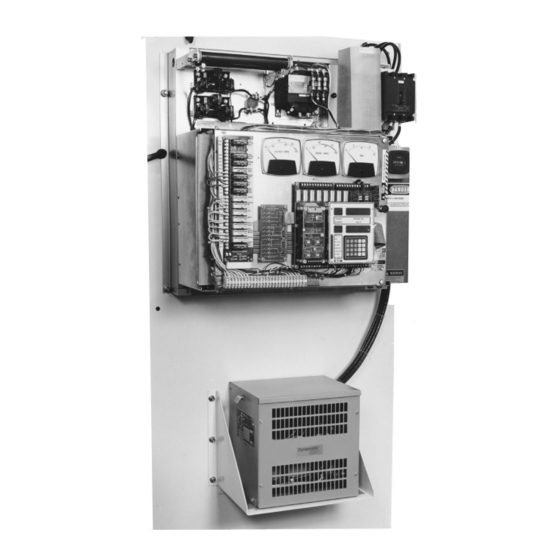
CES CONTROLLER controller. The autotransformer steps up the line voltage The basic CES press drive controller has proven to be from 480 VAC to 600 VAC. FU1, FU2 and FU3 are fast readily adaptable to synchronization (position) control. -
Page 9: Keypad Programming
The position information is then used to set a reference profile based on stored data of up to 6 angles and 6 predetermined speeds. Details are further described under "CES Digital Master Regulator (DMR)" and "Press Operating Modes." FIELD ADJUSTMENTS Some operator control adjustments can be made in the field. -
Page 10: Ces Digital Master Regulator (Dmr)
CES DIGITAL MASTER REGULATOR (DMR) operation of the CES controller. Parameters are scaled The DMR Controller is a microprocessor based solid in user units when applicable. state electronic control system operating in conjunction with a CES press drive controller. It provides the Upon power-up in the field, the values will be set by the interface with the press manufacturer's control. -
Page 11: Press Control Interface - Commands Accepted
MICRO INCH: in a "GO" status by the press control. The release of the The micro inch signal indicates that the CES controller is friction brake through the air pressure switch and/or the directed to operate at the micro inch speed. The micro... -
Page 12: Press Control Interface - Output Signals
The control power on signal is provided by the press The stop main motor fault signal from the CES controller control to activate the 115 VAC control power to the CES to the press control requests an emergency stop controller. This will close a contact in the secondary of condition. -
Page 13: Press Control Interface - Serial
4. Clutch contactor ON signal is present I. RUN MODE (NORMAL) Note: if the brake contactor drops out or clutch ON is The CES controller is in the run mode if the following removed, CR1 drops out immediately. If the enable is conditions exist:... - Page 14 The inch forward mode will be indicated by the "Inch" LED on the keypad and display board. II. INCH FORWARD MODE (RUN AT) The CES controller will be in the inch forward mode if the following conditions exist: 1. Enable signal is present...
- Page 15 III. INCH REVERSE MODE (RUN AT) The micro inch forward mode will be indicated by the The CES controller will be in the inch reverse mode if the "Micro Inch" LED on the keypad and display board. following conditions exist: V.
- Page 16 0212 Reverse Command Fault - The presence of a When the over-speed fault is generated, the CES reverse command without an inch or a micro controller functions in the following manner. inch command.
- Page 17 Stop-On-Top Faults - There are 8 stop-on-top faults. drive will be in a fault mode condition and cannot be They will cause the CES controller to execute a normal restarted without resetting the fault. If the press does stop upon reaching the top of the press stroke. These not reach the stopping angle in 1.5 times the press cycle...
-
Page 18: Press Control Parameters
17. Exit test mode by setting parameter No. 60 to the OFF condition from the keypad and display board The CES controller will be in the ready mode if the following conditions exist: An LED located on the keypad and display board indicates the test mode. - Page 19 3. The speeds will be four digits, with an implied decimal point, in hundredths of a stroke per minute. 6. The speeds will be four digits, with an implied 4. The CES monitor data will have the format indicated decimal point, in hundredths of a stroke per minute. Table minute second.
- Page 20 A typical program to run a press with a Manual Speed pot and use the slowdown function to get good parts would be set up as follows: 1. Angle No. 1 = 180 degrees 2. Manual Speed pot = 16 SPM 3.
-
Page 21: Section 3 - Operation
The many types of clutch and brake units built by various press builders and their suppliers can all be The heart of the CES stamping press controller is the classified in one of the following categories: 1) Positive CES Controller. Its purpose is to provide high response clutch and brake;... -
Page 22: Power Amplifier
LEM in constant. A current feedback loop is used with the CES series with the clutch and brake coils. This network acts... -
Page 23: Ces Logic Board
Any high on the control line inhibits CES CONTROLLER PARAMETERS further operation. Parameter values are set either from the keypad or through the serial interface. - Page 24 to the desired number with the up arrow (↑) or down through 25. The remaining parameters can be modified arrow (↓). from the keypad. Parameters that can be downloaded through a serial interface are numbered 30 through 43. A list of all parameter numbers is included in Table 3-3 Some parameters have built in limits.
-
Page 25: Keypad Programming
F1, F2, ENTER. Use the up or down the system performance. Refer to CES Controller arrow until the word “UNLOCK” is displayed on the Parameters on the previous page for an explanation of DMR. - Page 26 Fast auto-repeat is also accomplished by pressing the Asterisk button and then pressing and holding one of the arrow buttons down. After releasing the arrow button (↓) for a period longer than one second, the up/down function will revert back to normal speed of operation. A faster up/down function is also available.
-
Page 27: Optional Features
OPTIONAL FEATURES OPERATING THE PRESS-ON-HOP Speed into the next stroke. This is the equivalent of the This term is used in reference to a press that is basically continuous mode of operation. If the signal is not operating in the single stroke mode. When the press is present at this point, the press will go to Creep Speed. - Page 28 Typical DMR Parameter and Fault Number Reference Chart Table 3-3 PARAMETER PARAMETER PARAMETER PARAMETER NUMBER NUMBER Not Used No. Of Speed Feedback Periods Average Speed Feedback - SPM Serial Interface Baud Rate Speed Reference - SPM Under-speed % Limit Average Speed Error (+/-) - SPM Die Contact Angle Effective Resolver Position Resolver Direction Selection...
- Page 29 Special DMR Parameter and Fault Number Reference Chart for DMR with Stop-On-Bottom Feature Table 3-4 PARAMETER PARAMETER PARAMETER PARAMETER NUMBER NUMBER Not Used No. Of Speed Feedback Periods Average Speed Feedback - SPM Serial Interface Baud Rate Speed Reference - SPM Under-speed % Limit Average Speed Error (+/-) - SPM Die Contact Angle...
-
Page 30: Section 4 - Start-Up And Adjustment
15-822-1, through 15-822-10, 115 volts to be present in the CES press control depending on the size of the mechanical unit. This when the circuit breaker is placed in the ON board has circuitry that performs the following functions: position. - Page 31 ON signal), 15 to 16 (across CR2) and 26 to 27 been activated (across the TD contact). g. Turn the CES circuit breaker to the ON position. b. The brake current will go to its maximum value, h. The DMR will remember that it is in the test as set by the Brake Current Limit potentiometer.
- Page 32 This completes the setup of the resolver. c. Send the following signals from the press control to the CES controller. Remove the signal after 12. Operate the Press in the Run Mode. making the prescribed check. When faults are simulated, send the fault reset signal from the a.
-
Page 33: Approximate Parameter Settings
APPROXIMATE PARAMETER SETTINGS Enter Creep Angle, parameter 42. Enter Stop Angle, parameter 43. Approximate parameter settings, which are furnished for Enter Creep Speed, parameter 44. trial only, are indicated in Table 4-1. Actual settings will Enter Max Speed, parameter 26. be determined during the press set-up. - Page 34 Typical Parameter Settings Table 4-1 *NOTE: Parameter No. 31 will be altered by either the Trim Speed Parameter Number Value pot or the Manual Speed pot, depending on which is used. Max press speed 480.00 Same as CL Meter Same as BR Meter 180.0 20.0* 90.0...
-
Page 35: Maintenance
W7 jumper on this board. If a replacement PCB assembly. Therefore, this manual Dynamatic is providing the power, it is required. If not, it limits troubleshooting to the sub-assembly level. Always must be removed with this in mind one DMR assembly check the obvious. -
Page 36: Renewal Parts And Service
60.4 K 15-822-8 84.5 K 84.5 K 15-822-9 124.0 K 84.5 K 15-822-10 84.5 K 84.5 K List of Spare Parts Common to All CES/DR Controls Recommended Dynamatic Part Description Symbol Qty. Number 15-242-57 CES logic interface indicator PCB assembly 15-358-502... - Page 37 Page is intentionally blank...
- Page 38 DRIVE SOURCE INTERNATIONAL INC. 7900 Durand Avenue, Bldg 3 Sturtevant, WI USA 53177 Toll Free: (800) 548-2169 Phone: (262) 554-7977 - Fax: (262) 554- 7041 Email: sales@dynamatic Web: www.dynamatic.com...
Need help?
Do you have a question about the CES and is the answer not in the manual?
Questions and answers