Sign In
Upload
Manuals
Brands
Dynamatic Manuals
Controller
4000
User Manuals: Dynamatic 4000 Analog Controller
Manuals and User Guides for Dynamatic 4000 Analog Controller. We have
7
Dynamatic 4000 Analog Controller manuals available for free PDF download: Instruction Manual, Instruction Sheet
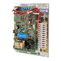
Dynamatic 4000 Instruction Manual (47 pages)
Brand:
Dynamatic
| Category:
Controller
| Size: 2 MB
Table of Contents
Table of Contents
2
Section 1
5
General Information
5
Introduction
5
Safety
5
Training
6
Receiving and Damage Claims
6
Warranty
6
Handling
6
Storage
6
Long Term Storage
7
Removal from Storage
7
Numbering System
7
Symbols Used in Illustrations
10
Section 2
11
4000 And 4050 Controller Description
11
Specifications
11
Basic Controller Assembly
12
Modification Pcb's
13
Packaging Options
13
Table 2-1 Standard Enclosed Model 4000 Controller
14
Table 2-2 Panel Mounted 4000 Controllers
15
Table 2-3 Panel Mounted 4050 Controllers
16
Section 3
18
Assembly
18
Identification
18
Main Printed Circuit Board Support
18
Modification PCB
19
Wiring
20
Section 4
21
Installation
21
Location
21
Mounting Panel Mounted Model 4000 and 4050 Controllers
21
Mounting an Input Transformer
22
Wiring
22
Programming Dip Switch
23
Section 5
25
Operation
25
Basic Controller Theory
25
Linear Acceleration Option
26
Fixed Brake Option
27
Spring Set Brake Option
28
Adjustable Brake Modification, 15-444-4
28
Alternate Speed Modification, 15-444-3
28
Tach Follower Modification, 15-444-1
29
Low Signal Follower Modification 15-446-1/5/101
29
Torque/Speed Modification, 15-444-5
29
Torque Limit Modification, 15-444-2
30
Dancer Position Modification, 15-444-7
30
Figure 5-3: Model 4000 Controller Schematic with 15-530-5 Main Assembly
31
Figure 5-4: Model 4050 Controller Schematic with 15-530-6 Main PCB Assembly
32
Mutuatrol® Modification, 15-446-2
33
Variable Air Volume Modification (VAV), 15-446-3/102
33
Linear Accel/Decel Modification, 15-446-4
33
Section 6
34
Start-Up and Adjustments
34
Tools Required
35
Power off Tests
35
Power on Tests
36
Set-Up of Main PCB Assembly
37
Basic Speed Control
37
LED Set-Up
38
Zero Adjust R19 with LED Monitor
38
Zero Adjust R19, Alternate Method
38
Max Speed/Volts R21
39
Max Speed/Volts R21 with LED Monitor
39
Max Speed/Volts R21, Alternate Methods
39
Time Constant (TC) Adjust R26
40
Accel Rate R18
40
Velocity Damping R22
41
Current Feedback, R20
42
Basic Torque Control (Used When Speed Control Is Not Used)
43
Section 7
44
Maintenance and Trouble Shooting
44
Maintenance
44
Trouble Shooting
44
If the Drive will Not Run
44
If the Drive Runs at Full Speed
45
Renewal Parts and Service
46
Advertisement
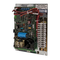
Dynamatic 4000 Instruction Manual (52 pages)
Stamping Press Controllers
Brand:
Dynamatic
| Category:
Controller
| Size: 6 MB
Table of Contents
Table of Contents
4
Section 1
7
General Information
7
Introduction
7
Safety
7
Training
7
Receiving and Damage Claims
8
Warranty
8
Handling
8
Storage
8
Long Term Storage
8
Removal from Storage
9
Section 2
10
General Description
10
Basic Controller Assembly
11
Drive Description and Application
12
Model 4000-4050 Comparison
13
Installation
13
Operation
13
Start-Up and Adjustments
13
Adjustment (W/O Speed Trip) Panel Outline Mounting Dimensions
15
Section 3
18
Installation
18
Mounting Panel Mounted Controllers
18
Mounting an Input Transformer
18
Main Printed Circuit Board Support
19
Modification PCB
19
Wiring
20
Programming Dip Switch
21
And 8.0 Adc Output (15-541-*)
22
Speed Trip and Minimum Speed Adjustment 208/230/460V Input and 5.5 Adc Output (15-541- 0007)
24
Input and 8.0 Adc Output (15-451-002*)
26
Section 4
32
Operation
32
Basic Controller Theory
32
Torque Limit Modification 15-44-2
33
Linear Acceleration Option
33
Fixed Brake Option
34
Spring Set Brake Option
34
Speed Trip Option
34
Section 5
36
Start-Up and Adjustments
36
Power off Test
36
Tools Required
36
Power on Test
37
Preliminary Adjustments
38
Set-Up Main PCB Assembly
38
Basic Speed Control (Without Torque Limit)
40
LED Set-Up
40
Max Speed/Volts R21, Alternate Methods
41
Control with Torque Limit Modification
43
Section 6
45
Maintenance and Troubleshooting
45
Maintenance
45
Troubleshooting
46
Renewal Parts and Service
47
Renewal Parts List
48
Loose Parts for 4050 Stamping Press Controller
51
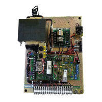
Dynamatic 4000 Instruction Sheet (15 pages)
with Auto Manual Low Signal Follower External Ratio Adjustment
Brand:
Dynamatic
| Category:
Controller
| Size: 2 MB
Table of Contents
Introduction
1
Table of Contents
2
Connection Diagram for Standard Enclosure 4000 Controller
3
Schematic Diagram for 4000 Controller
4
Connection Diagram for 4000 Panel Mount and 4050 Controllers
5
Low Signal Follower Modification PCB 15-446-5/0102
6
Schematic Diagram for 4050 Controller
6
Modification PCB Mounting
7
General Description
7
Visual Inspection
7
Preliminary Adjustments
7
Operator Controls
7
Main PCB 15-530-5 or 15-530-6
8
Trimpot Illustration
8
Low Signal Follower Mod PCB
9
Adjustment Procedure
9
Zero Adjust R19 with LED Monitor
9
Zero Adjust R19, Alternate Method
9
Max Speed/Volts R21
9
Max Speed/Volts R21 with LED Monitor
9
Max Speed/Volts R21, Alternate Methods
10
Time Constant (TC) Adjust
10
Current Feedback R20
10
Accel Rate R18
11
Velocity Damping R22
11
Automatic Operation
11
Circuit Diagram for Input Signals
12
Greater than 7.5 VDC
12
Renewal Parts List
14
Advertisement
Dynamatic 4000 Instruction Sheet (14 pages)
Brand:
Dynamatic
| Category:
Controller
| Size: 2 MB
Table of Contents
Introduction
1
Table of Contents
2
Connection Diagram for Standard Enclosure 4000 Controller
3
Schematic Diagram for 4000 Controller
4
Connection Diagram for 4000 Panel Mount and 4050 Controllers
5
Schematic Diagram for 4050 Controller
6
Low Signal Follower Modification PCB 15-444-2
6
Modification Pcb Mounting
7
General Description
7
Preliminary Adjustments
7
Operator Controls
7
Main PCB 15-530-5 or 15-530-6
7
Trimpot Illustration
8
Torque Limit
8
Adjustment Procedure
9
Zero Adjust R19 with LED Monitor
9
Zero Adjust R19, Alternate Method
9
Max Speed/Volts R21
9
Max Speed/Volts R21 with LED Monitor
9
Max Speed/Volts R21, Alternate Methods
10
Time Constant (TC) Adjust R26
10
Current Feedback R20
10
Accel Rate R18
11
Velocity Damping R22
11
HI Damping R20
11
Torque Limit PCB 15-444-2
11
Torque Limit PCB 15-444-2
12
Jog at Run Speed
12
Renewal Parts List
13
Dynamatic 4000 Instruction Sheet (13 pages)
with Auto Manual Tach Follower
Brand:
Dynamatic
| Category:
Controller
| Size: 2 MB
Table of Contents
Introduction
1
Table of Contents
2
Connection Diagram for Standard Enclosure 4000 Controller
3
Schematic Diagram for 4000 Controller
4
Connection Diagram for 4000 Panel Mount and 4050 Controllers
5
Schematic Diagram for 4050 Controller
6
Tach Follower PCB 15-444-1
6
General Description
7
Visual Inspection
7
Preliminary Adjustments
7
1 Operator Controls
7
2 Main PCB 15-530-5 or 15-530-6
7
Trimpot Illustration
8
3 Tach Follower Mod PCB 15-444-1
8
Max Speed/Volts R21 with LED Monitor
9
Adjustment Procedure
8
Zero Adjust R19 with LED Monitor
9
Zero Adjust R19, Alternate Method
9
4 Max Speed/Volts R21
9
6 Time Constant (TC) Adjust R26
10
7 Current Feedback R20
10
Max Speed/Volts R21, Alternate Methods
10
8 Accel Rate R18
10
9 Velocity Damping R22
11
Renewal Parts List
12
Dynamatic 4000 Instruction Sheet (14 pages)
Brand:
Dynamatic
| Category:
Controller
| Size: 2 MB
Table of Contents
Introduction
1
Table of Contents
2
Connection Diagram for Standard Enclosure 4000 Controller
3
Schematic Diagram for 4000 Controller
4
Connection Diagram for 4000 Panel Mount and 4050 Controllers
5
Schematic Diagram for 4050 Controller
6
Torque Limit Modification PCB 15-444-2
7
Modification PCB Mounting
7
General Description
7
Preliminary Adjustments
8
Adjustment Procedure
9
Zero Adjust R19 with LED Monitor
9
Zero Adjust R19 Alternate Method
9
Max Speed/Volts R21
9
Max Speed/Volts R21, Alternate Methods
10
Time Constant (TC) Adjust R26
10
Current Feedback R20
10
Accel Rate R18
11
Velocity Damping R22
11
HI Damping R20
11
Renewal Parts List
13
Dynamatic 4000 Instruction Sheet (13 pages)
with Dancer Position
Brand:
Dynamatic
| Category:
Controller
| Size: 1 MB
Table of Contents
Introduction
1
Table of Contents
2
Connection Diagram for Standard Enclosure 4000 Controller
3
Schematic Diagram for 4000 Controller
4
Connection Diagram 4000 Panel Mount and 4050 Controller
5
Dancer Position Modification PCB 15-444-7
6
Schematic Diagram for 4050 Controller
6
Modification PCB Mounting
7
General Description
7
Visual Inspection
7
Preliminary Adjustment
7
Dancer Position
8
Adjustment Procedure
9
For Winder Operation Only
10
For Payoff Operation Only
10
Renewal Parts List
12
Advertisement
Related Products
Dynamatic 4050
Dynamatic 4500
Dynamatic 015-000248-2002
Dynamatic 015-000248-2003
Dynamatic 015-000248-2004
Dynamatic 15-533-1015
Dynamatic 15-539-0015
Dynamatic 15-539-14
Dynamatic 15-551-1015
Dynamatic 15-553-0015
Dynamatic Categories
Controller
Computer Hardware
Wheelchair
DC Drives
More Dynamatic Manuals
Login
Sign In
OR
Sign in with Facebook
Sign in with Google
Upload manual
Upload from disk
Upload from URL