Dynamatic 4000 Instruction Sheet
With dancer position
Hide thumbs
Also See for 4000:
- Instruction manual (52 pages) ,
- Instruction sheet (14 pages) ,
- Instruction sheet (13 pages)
Table of Contents
Advertisement
Quick Links
Instruction Sheet
IS-539-16
revised 2019
15-533-1016 Panel Mount 4000 (4.3 A Controller)
15-551-1016 Standard Enclosure 4000 (4.3 A Controller)
15-539-0016 Panel Mount 4050 (8 A Controller)
15-553-0016 Standard Enclosure 4050 (8 A Controller)
Model 4000 and 4050 with Dancer Position
Introduction:
These instructions relate specifically to the
following Model 4000 and 4050 controllers
which are assembled for Speed Control with
the Dancer Position modification.
Connection Diagram, schematic diagram,
switch
programming,
connection, adjustment procedure and
recommended spare parts list for these
specific assemblies are contained in this
instruction sheet. Any differences between
theses two controllers are clearly noted.
Use instruction manual IM-130006-83XX
with this instruction sheet for complete
installation, operation and maintenance
instructions.
Caution: Above ground electrical potentials
can be hazardous. Always disconnect
electrical power before working on the
controller.
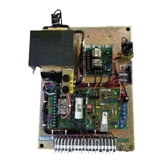
*Heat sink Assembly, HS1, and its wiring
apply only to the Model 4050 controllers.
These parts are not supplied on Model 4000
controllers. The parts are mounted on the
15-530-5 main 4000 board.
1
plug
wiring
Drive Source International/Dynamatic
7900 Durand Ave Bldg 3 Sturtevant, WI 53177
sales@dynamatic.com
800-548-2169 •
www.Dynamatic.com
Advertisement
Table of Contents

Related Manuals for Dynamatic 4000


Summary of Contents for Dynamatic 4000
-
Page 1: Introduction
*Heat sink Assembly, HS1, and its wiring apply only to the Model 4050 controllers. These parts are not supplied on Model 4000 controllers. The parts are mounted on the 15-530-5 main 4000 board. -
Page 2: Table Of Contents
Introduction: Connection Diagram for Standard Enclosure 4000 Controller Schematic Diagram for 4000 Controller Connection Diagram 4000 Panel Mount and 4050 Controller Schematic Diagram for 4050 Controller Dancer Position Modification PCB 15-444-7 Modification PCB Mounting General Description Visual Inspection Preliminary Adjustment... -
Page 3: Connection Diagram For Standard Enclosure 4000 Controller
Connection Diagram for Standard Enclosure 4000 Controller ED-58216... -
Page 4: Schematic Diagram For 4000 Controller
Schematic Diagram for 4000 Controller... -
Page 5: Connection Diagram 4000 Panel Mount And 4050 Controller
Connection Diagram 4000 Panel Mount and 4050 Controller ED-56816 Note 1: This Equipment must be installed in compliance with National electrical code and all applicable state and local codes Note 2: Transformer may be supplied as a winding in the ac motor or as a separate item. Standard connections to winding in mechanical unit and loose transformer connections are both shown above. -
Page 6: Schematic Diagram For 4050 Controller
Schematic Diagram for 4050 Controller Dancer Position Modification PCB 15-444-7... -
Page 7: Modification Pcb Mounting
General Description The Dancer Position modification converts the standard 4000 and 4050 controllers into a position control system. The feedback quantity to the Main PCB becomes the position of a Dancer Operated potentiometer rather than the drive output shaft velocity. -
Page 8: Dancer Position
a. For Winder operation only, set the Dancer Position potentiometer R5 to 0% (Full CCW) b. For Payoff operation only, set the Dancer Position potentiometer R5 to 0% (Full CCW). c. Note location of Start and Stop pushbuttons Main PCB 15-530-5 or 15-530-6 The pots used are screwdriver adjust, single turn pots. -
Page 9: Adjustment Procedure
*Typical product number stamped on mechanical unit nameplate: 1. A1-100214-0053, specific mechanical model is AC-214 2. B2-100210-0008, specific mechanical model is AS-21 Figure1: Trimpot Illustration D. The Dancer Operated potentiometer R55 is located externally to the controller and operator station and is driven by a moveable dancer roll. Adjustment Procedure Do not have material attached to winding roll for this procedure. -
Page 10: For Winder Operation Only
ON (or the drive shaft begins to rotate), the LED should start flashing. Now just back off slowly until the flashing stops. Remove power. For Winder Operation Only a. Connect a voltmeter on the 0-10 Vdc range to the Dancer Operated pot R55 terminals - P1 and +P7. - Page 11 of the Dancer Operated pot. Adjust pot linkage if required until these readings are obtained. b. Lower dancer roll to the desired running height and hold it in this position. c. Connect a voltmeter on the 0-50 Vdc range to clutch coil leads -C1 and +C2. (Press the Start pushbutton) The meter should read zero.
-
Page 12: Renewal Parts List
Renewal Parts List for Standard 4000 & 4050 Controllers with Dancer Position Part Number Description Legend Model 4000 Controllers 15-530-0005 Main PCB Assembly ** 27-123-0001 Mini-Jumper 32-018-4091 Fuse, 4 Amp, 250 V FU1, 2 53-398-0001 Relay, 4pdt, plug-in 15-533-1016 Panel Mount... - Page 13 Drive Source International/Dynamatic 7900 Durand Ave Bldg 3 Sturtevant, WI 53177 sales@dynamatic.com 800-548-2169 • www.Dynamatic.com...
Need help?
Do you have a question about the 4000 and is the answer not in the manual?
Questions and answers