
Related Manuals for Dynamatic EC 2000-CES


Summary of Contents for Dynamatic EC 2000-CES
- Page 1 EC 2000 – CES Stamping Press Position Controller Instruction Manual Sturtevant, Wisconsin, USA 53177 Telephone: 262-554-7977 Fax: 262-554-7041 Toll Free: 800-548-2169 www.dynamatic.com sales@dynamatic.com...
-
Page 2: Table Of Contents
EC-2000-CES MANUAL Table of Contents SECTION 1 - THEORY OF OPERATION ....................... 6 SECTION 2 – MODELS AND PART NUMBERS ....................9 SECTION 3– SPECIFICATIONS ......................... 10 Features ............................. 10 Power and Load Ratings ......................10 Electrical Protection ........................10 Environmental Ratings ....................... - Page 3 EC-2000-CES MANUAL Menu F: PROCESS ........................29 Menu G: FAULT .......................... 30 8.7 Menu H: FAULT TIMER SETUP ......................31 8.8 Menu I POSITION ERROR SETUP ....................34 8.9 Menu J: METER SETUP ........................35 8.10 Menu K: SERIAL OPTIONS ......................35 SECTION 9 –...
- Page 4 Table of Figures ................7 Figure 1: Eddy Current Drive Block Diagram ..................8 Figure 2: EC 2000-CES Keypad Display ..............15 Figure 3: Standard Panel Dimensions (Not to scale) ..............16 Figure 4: Keypad Cutout Template (to Scale, Inches) ..................
- Page 5 EC-2000-CES MANUAL Listing of Tables ..................... 9 Table 1: Models and Part Numbers ....19 Table 2: Clutch Control Board Programmable Jumpers Default Settings in Green ................19 Table 3: Follower Set Point Jumper Settings ..............21 Table 4: Brake Control Board Programmable Jumpers ..................
-
Page 6: Section 1 - Theory Of Operation
EC 2000-CES control. The EC 2000-CES uses digital technology to provide a flexible, low noise control for today’s high tech industrial environment. It provides setup and programming via a keypad with a user friendly alphanumeric display;... -
Page 7: Figure 1: Eddy Current Drive Block Diagram
EC-2000-CES MANUAL Figure 1 : Eddy Current Drive Block Diagram... -
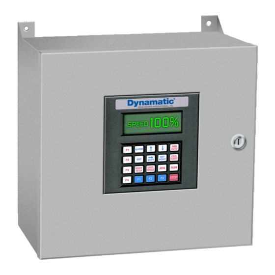
Page 8: Figure 2: Ec 2000-Ces Keypad Display
EC-2000-CES MANUAL Figure 2 : EC 2000-CES Keypad Display... -
Page 9: Section 2 - Models And Part Numbers
EC-2000-CES MANUAL SECTION 2 – MODELS AND PART NUMBERS Table 1: Models and Part Numbers Required Dynamatic Part Output Maximum Input Voltage (50/60 Notes Number Voltage Current 015-000248-2002 300VDC * 135A 600V 1ph ** SCRs in F.W. bridge rectification 015-000248-2003... -
Page 10: Section 3- Specifications
EC-2000-CES MANUAL SECTION 3– SPECIFICATIONS Features Direct Drop in Replacement for Dynamatic Digital CES Controls, Galco or Control Techniques Voltage ranges available from 45 – 300VDC Up to 135 amps output (see Table 1 for model list) ... -
Page 11: Environmental Ratings
EC-2000-CES MANUAL Environmental Ratings Operating temperature range: 0°C to 40°C (enclosed or panel mount) Storage temperature: -10°C to 75°C maximum Humidity: 95% non-condensing Elevation: to 1500 meters without derating Electrical Noise The control is immune to showering arc noise as specified by NEMA 519 test procedures. - Page 12 EC-2000-CES MANUAL...
-
Page 13: Section 4 - Control Operation Modes
EC-2000-CES MANUAL SECTION 4 – CONTROL OPERATION MODES Control Modes Speed (AC Tachometer Generator or Speed Pickup) Torque (Current Feedback) Position & Speed (Resolver Feedback) Mode of Operation Manual/Auto o Allows the use to switch between an automatic signal (i.e. 4-20mA or 0-10V) and the control potentiometer in Speed Mode ... -
Page 14: Section 5 - Inputs/Outputs
EC-2000-CES MANUAL SECTION 5 – Inputs/Outputs Analog Inputs Potentiometer/Reference Voltage o Used for setpoints Digital Inputs Clutch On Enable High Enable Low Inch High Inch Low Reverse Continuous Mode Fault Reset Analog Outputs ... -
Page 15: Section 6 - Installation
EC-2000-CES MANUAL SECTION 6 – INSTALLATION Panel & Keypad Layouts Figure 3 : Standard Panel Dimensions (Not to scale) -
Page 16: Figure 4: Keypad Cutout Template (To Scale, Inches)
EC-2000-CES MANUAL Figure 4: Keypad Cutout Template (to Scale, Inches) -
Page 17: Figure 5: Keypad Dimensions (To Scale)
EC-2000-CES MANUAL Figure 5 : Keypad Dimensions (to Scale) -
Page 18: Mounting Hardware
¼” - 20 Bolts, Flat Washers, Lock Washers (Not included) Keypad o Included Wiring Dynamatic recommends adhering to the National Fire Protection Association’s “NFPA 70: National Electrical Code” codes and standards for proper branch protection, SCCR ratings, and ampacity ratings. o https://www.nfpa.org/codes-and-standards/all-codes-and-standards/list-of- codes-and-standards/detail?code=70 ... -
Page 19: Hardware Jumper & Potentiometer Setup
EC-2000-CES MANUAL Hardware Jumper & Potentiometer Setup a. Jumpers and Potentiometers on Clutch Driver Board 015-001201-0012 Table 2: Clutch Control Board Programmable Jumpers Default Settings in Green JUMPER PARAMETER POSITION “A” POSITION “B” Follower Operation Pulse Pickup Tach. Generator (Not Used on CES Control) (TB2-17) (TB2-18 &... -
Page 20: Figure 6: Clutch Control Board Layout
EC-2000-CES MANUAL Figure 6 : Clutch Control Board Layout Location of Jumpers on the Clutch power Board Note that Jumpers J3 and J6 are located under the logic circuit board, if it is installed. -
Page 21: Figure 7: Brake Control Board Layout
EC-2000-CES MANUAL b. Jumpers and Potentiometers on Clutch Driver Board 015-001201-0020,21 Table 4 : Brake Control Board Programmable Jumpers Default Settings in Green JUMPER PARAMETER POSITION “A” POSITION “B” Resolver Reference Internal Power Supply External Power Supply Resolver Reference Internal Power Supply External Power Supply Resolver Reference Internal Power Supply... -
Page 22: Section 7 - Keypad
Initial programming must be done with the keypad. The keypad is plugged into the RS-235 port mounted on the control side plate. Dynamatic® part number: 037-000544-01 (Keypad) Table 5: Keypad Button Descriptions Function Notes Allows user into a menu or submenu; confirms value... -
Page 23: Section 8 - Programming
EC-2000-CES MANUAL SECTION 8 – PROGRAMMING Menu A: Control Setup 1. CONTROL TYPE Position (Default) o Uses the Resolver for Position Control Speed o Uses the AC Tachometer Feedback for speed feedback and control depending on Jumper J4 ... - Page 24 EC-2000-CES MANUAL 5. TACH PULSES/REV The control tachometer feedback comes from a mechanical unit tachometer or press resolver depending on the position of Jumper J4 on the clutch driver board. Set the speed feedback frequency for the AC tachometer generator based on the resolver or mechanical unit you have.
- Page 25 EC-2000-CES MANUAL 8. CLUT CNTRL OFFSET A programmable offset for the clutch output. This compensates for electrical dead band in the control, as well as mechanical unit response. 0–10000. This value should be increased to the highest value that will not cause motion at command signal = 0. Lower values for low current controls.
-
Page 26: Menu B: Clch Performance
Rarely used (Default = 0 RPM) 17. BOOT START DELAY Delays the boot up sequence of the EC 2000-CES. This is used for large more unstable power supplies that disrupt the controllers boot up sequence when switching on (Default: 0 sec). -
Page 27: Menu C: Accel/Decel Setup
Default = 0% 7. ENABLE CURRENT LOOP The EC 2000-CES has two PID loops (as seen in the previous parameters), speed and current, where the speed PID loop is fed into the current PID loop. This parameter allows the user to disable the current PID loop. This is typically is used in Systems with fast changing outputs that require very quick response. - Page 28 EC-2000-CES MANUAL 2. Brake Current Limit Enter the coil current limit, which is equal to or less than the clutch coil rating. Note, limiting the coil current to less than its rated value will reduce the amount of torque. Default = 100 Amp 3.
-
Page 29: Menu F: Process
EC-2000-CES MANUAL 9. BRAKE DEADBAND Offset Between the actual set point and the beginning of clutch action for the PID loops. Used to prevent oscillation between clutch and brake when running at steady speed (Default = 50 RPM) 10. BRK OFF DLY This is a programmable delay from issuance of the stop command to release of the clutch contactor by the control. -
Page 30: Menu G: Fault
EC-2000-CES MANUAL 13. ANGLE #6 14. SPEED #6 15. CREEP ANGLE 16. CREEP SPEED If the control is in single stroke mode when it passes the creep angle, it will run at the creep speed Programmed Speed for Creep Speed: 0 to Max SPM 17. -
Page 31: Menu H: Fault Timer Setup
EC-2000-CES MANUAL 5. PRIOR FAULT #4 Allows the user to see the fourth previous fault (read only). 6. CLEAR FAULT If enabled, the control will clear the fault. Note: If enabled when there is no fault, fault history will be cleared. ... - Page 32 EC-2000-CES MANUAL 5. CL CONT ON TOO SHT When stopping the clutch contactor is delayed. If the delay is longer than This parameter a fault is generated Fault 225 Default 300 MS 6. INCH REV CHG TIM Inch – Micro-Inch – Rev signals cannot be changed while engaged. Additionally reverse must have inch enabled.
- Page 33 EC-2000-CES MANUAL 11. CL CUR ON % LONG Percentage of Clutch current for on too long timer Fault 320 Default = 30% 12. BR CUR ON TO LONG Timer for brake current on too long Fault 321 Default = 5000 MS 13.
-
Page 34: Menu I Position Error Setup
EC-2000-CES MANUAL 19. UND SPD TRIP % Percentage of max brake current for on too long timer Fault 313 Default = 30 % 20. FDBK FLT TIME Tachometer Feedback Fault Timer Fault 205 Default = 2000 MS 21. FDBK FLT CL CUR % Tachometer Feedback Fault % FL Amps Fault 205 Default = 30 %... -
Page 35: Menu J: Meter Setup
EC-2000-CES MANUAL Apply Brake Advance Advances the braking action ahead of the stop angle programed. Default = 0 Degrees 3. Wrong Direction Error Amount of motion allowed in the reverse direction from the programmed direction in degrees before a fault is set. Fault 206 Default = 36 Degrees 8.9 Menu J: METER SETUP... -
Page 36: Section 9 - Press Control Operation -- Wired Interface
EC-2000-CES MANUAL 3. Access All Menus (Allows Access to Menus not normally used. Consult Factory) Choices Are: ENABLE DISABLE Default: Disable (Reverts to Disable when power is cycled to the control.) 4. Display Timeout -- Disables the display after 30 seconds. Display will return if enter or exit buttons are pressed. -
Page 37: Control - Output Signals
EC-2000-CES MANUAL MICRO INCH: The micro inch signal indicates that the controller is directed to operate at the micro inch speed. The two enables and clutch on signal are need as well. The micro inch command can only be changed when enable is not present;... -
Page 38: Press Control Interface - Serial Port
EC-2000-CES MANUAL through I.11. The brake control board of the controller opens a solid-state relay contact for the normal stop signal to the press control. STOP MAIN MOTOR FAULT (OUTPUT): The stop main motor fault signal from the controller to the press control requests an emergency stop condition. -
Page 39: Signals For Customer's Recorder
EC-2000-CES MANUAL 9.4 SIGNALS FOR CUSTOMER’S RECORDER The controller provides two addition signals: Pulse Output Seen by Control feedback system (Logic Board TB2-1,2) Analog Output 0 to 10V (Set point used by control TB2-20,21) 9.5 BRAKE CONTACTOR A brake contactor is provided which will be closed under simultaneous conditions of control power ON being available and brake current fault not being present. - Page 40 EC-2000-CES MANUAL Table 7: Parameter Locations Parameter Number Data Angle No. 1 Speed No. 1 (manual)* Angle No. 2 Speed No. 2 Angle No. 3 Speed No. 3 Angle No. 4 F.10 Speed No. 4 F.11 Angle No. 5 F.13 Speed No.
- Page 41 EC-2000-CES MANUAL The inch mode will be indicated by display of the "Inch H" on the keypad display. INCH REVERSE MODE (SET UP) The controller will be in the inch reverse mode if the following conditions exist: 1. Enable signals are present 2.
- Page 42 EC-2000-CES MANUAL MICRO INCH REVERSE MODE (SET UP) The controller will be in the micro inch reverse mode if the following conditions exist: 1. Enable signals are present 2. No fault is present 3. Reverse is not present 4. Micro Inch is present 5.
-
Page 43: Section 10 - Startup & Adjustment
10.1 POWER CONVERSION The CES Press Control provides control for the full range of Dynamatic press drives the power conversion circuitry operates from 480 volts (+10%, -15 %) input and provides a maximum of 600 volts dc coil excitation voltage. -
Page 44: Clutch Control Board
EC-2000-CES MANUAL Reads resolver. Converts data to press angle and calculates the desired speed in RPM based on the current angle. The speed command is then sent to the clutch control board via an analog output. Stores all parameters and sends control parameters to clutch control board via serial port. ... - Page 45 EC-2000-CES MANUAL On the control keypad, enter the test (local control) mode as follows: Press the “enter” key. Use the “down” arrow until you reach “SERIAL OPTIONS” Press the “enter” key. Use the “”up” arrow key until you reach “EC-2000 MENUS” Press the “enter”...
-
Page 46: Start-Up Procedure
EC-2000-CES MANUAL 37. To calibrate the brake go to Menu D BRAK PERFORMANCE - Item 11 BRAK CUR SCALE and follow the same procedure as for the clutch. 38. Press “p1” to return to clutch control mode to test the clutch and brake. If the brake doesn’t engage long enough to get a good reading then you can increase the brake delay time. - Page 47 EC-2000-CES MANUAL Resolver Adjustment 1. Enter program mode and go to Menu F PROCESS Item 18 RESOLVER OFFSET. 2. Inch the press to top “0” Degrees. Adjust Item 18 using “up” or “down” arrows until the POS reading on the display equals the press angle “0” degrees. 3.
-
Page 48: Section 11 - Fault Listing & Descriptions
EC-2000-CES MANUAL SECTION 11 – FAULT LISTING & DESCRIPTIONS 11.00 FAULT LIST 11.01 LEVEL 100 FAULTS Stop Motor Faults FAULT 101 Over Speed Over Speed Fault occurs when drive speed is over the set point by the % of span set in over speed trip % for the time set in over speed trip time. - Page 49 EC-2000-CES MANUAL FAULT 212 Reverse Command without Inch or Micro Inch If Reverse is enabled and neither inch or Micro Inch are enabled and the clutch is engaged, after a programed time the control will fault Time Parameter Group H Item 6 ...
-
Page 50: Level 300 Faults
EC-2000-CES MANUAL Time = Parameter Group H, Item 15 FAULT 229 Brake Contactor Open In normal operation the brake contactor is closed. If it opens for the programmed time a fault is set. Parameter Group H, Item 1 FAULT 231 Controller Internal Communication Error The controller has two microprocessors. - Page 51 EC-2000-CES MANUAL If the control clutch current is above the programmed % of max current for the programmed time limit a fault is generated. Time = Parameter Group H, Item 10, % = Parameter Group H, Item 11 FAULT 321 Brake Current On Too Long If the control brake current is above the programmed % of max current for the programmed time limit a fault is generated.
-
Page 52: Section 12 Press Control Interface - Serial Port
EC-2000-CES MANUAL SECTION 12 PRESS CONTROL INTERFACE - SERIAL PORT The serial interface assembly makes it possible for the CES-EC-2000 control to communicate with another microprocessor, main computer or logic controller. This communication link is an RS-422 converter and a 232 data splitter module that is mounted on the control side panel. These modules then plug in to the controller bake board and multiplex with the keypad to communicate. -
Page 53: Serial Port Parameter Data Packet Instructions
EC-2000-CES MANUAL 14. Stop Angle = 356.5 degrees 15. On the keypad, enter: Creep Speed = 4 SPM 12.1 SERIAL PORT PARAMETER DATA PACKET INSTRUCTIONS The press run data packet should contain the following information, and in the order given: 1. -
Page 54: Serial Port Parameter Data Packet Instructions (Alternate Method)
EC-2000-CES MANUAL 12.2 SERIAL PORT PARAMETER DATA PACKET INSTRUCTIONS (ALTERNATE METHOD) It is also possible to write less than a complete data packet. Use the following method. 1. ASCII characters AA in positions 1 & 2. 2. Place the data you want to write in the proper location. For example if you wanted to change Speed No. -
Page 55: Serial Port Fault Report Data Packet Content
EC-2000-CES MANUAL 12.5 SERIAL PORT FAULT REPORT DATA PACKET CONTENT : Control Fault Data Format Table 9 Packet Number Data 1 through 2 3 through 6 Current Fault 7 through 10 Prior Fault #1 11 through 14 Prior Fault #2 15 through 18 Prior Fault #3 19 through 22... -
Page 56: Serial Port Connections
EC-2000-CES MANUAL Table 10: Control Monitor Data Format Packet Number Data 1 through 2 3 through 6 Inch Speed 7 through 10 Micro Inch Speed 11 through 14 Creep Speed 15 through 18 Auto acceleration rate 19 through 22 Auto deceleration rate 23 through 26 Manual acceleration rate 27 through 30... -
Page 57: Section 13 - Troubleshooting
EC-2000-CES MANUAL SECTION 13 – TROUBLESHOOTING 13.0 EC-2000-CES Press Drive Control – Troubleshooting Caution: these instructions should be read and clearly understood before working on the CES press control. Warning: Equipment is at or above line voltage extreme care must be observed when working on energized equipment. -
Page 58: Trouble Shootng 100 Level Stop Motor Faults
EC-2000-CES MANUAL 13.1 TROUBLE SHOOTNG 100 LEVEL STOP MOTOR FAULTS 100 Level: This fault results in the press stopping and signals the stopping of the main motor: Over speed fault. An over speed condition exists when the tach feedback exceeds the speed reference by a value determined in parameters H.16 &... - Page 59 EC-2000-CES MANUAL Press movement in wrong direction fault. Press movement in wrong direction contrary as set by parameter I.3 (wrong direction degrees) Possible causes: Improper or loose wiring of resolver check and repair. Incorrect setting of parameter F.19 (For-Rev Resolver). Loose plug in resolver chip on brake board –...
- Page 60 EC-2000-CES MANUAL Inch or micro inch enable fault. Presences of both inch and micro inch commands with an enable. Possible causes: Press control is sending both signals Defective brake control board input. Reverse command fault. The presence of a reverse command without either an inch or micro inch command.
- Page 61 EC-2000-CES MANUAL Clutch contactor on too long. Delay longer than setting in parameter H.4 Possible causes: Press control delay is too long Brake off delay is too long. Check parameter D.10. Contactor stays on till brake delay ends. Clutch Contactor sticking Clutch auxiliary contact sticking.
-
Page 62: Trouble Shootng 300 Level Stop On Top Faults
EC-2000-CES MANUAL Enable before clutch cool down expired fault. Enabling the CES controller before the cooldown period has expired following a clutch current fault. Possible causes: Operator error following a clutch current fault. Defective brake control board. Enable before clutch cool down expired fault. Enabling the CES controller before the cooldown period has expired following a clutch current fault. - Page 63 EC-2000-CES MANUAL Clutch and brake current overlap fault. Overlap fault occurs when clutch and brake current are present at the same time. Allowable limits are 20% and time as set in parameter H.9. Possible causes: Clutch or Brake SCR’s not firing properly Clutch or brake LEM’s are not working Clutch control or brake control boards not firing SCR’s properly.
-
Page 64: Trouble Shooting. No Fault Displayed
EC-2000-CES MANUAL Micro inch change fault. If the micro inch command is changed while the enable is present this fault will occur. Possible Causes: Check operator error or interface problem. Check LED Input module for micro inch command. Defective brake control board Reverse change fault. -
Page 65: Keypad Does Not Respond. Display Works
EC-2000-CES MANUAL 13.42 Keypad Does Not Respond. Display works: Possible causes: Press Control RS-422 Serial Connections are Incorrect. Defective RS-232 Data Splitter Defective RS-422 Data Converter Defective Keypad Display. Bad cable connections Defective brake control board 13.43 Control does not engage. No faults: Possible causes: Press control is not sending signals. -
Page 66: High Voltages Fuses Blow On Power Up
EC-2000-CES MANUAL 13.46 High Voltages Fuses blow on power up: Possible causes: If the fuses blow on startup or while stopping the problem is likely with the brake circuit Fault or ground in brake coil circuit. Meg and Ohm coils to check. Defective SCR’s . -
Page 67: Unstable Speed Slowing Or Braking
EC-2000-CES MANUAL 13.51 Unstable Speed Slowing or Braking: Possible causes Tuning Parameters. Check if current loop is disabled. Try disabling it if not. (parameter B.7) Too much brake dead band. Try setting to “0” RPM. Parameter D.9. Tuning Parameters. Try increasing speed brake proportional gain parameter D.6 Tuning Parameters. - Page 68 Drive Source International, Inc. Drive Source International, Inc. Sturtevant, Wisconsin, USA 53177 Telephone: 262-554-7977 Fax: 262-554-7041 Toll Free: 800-548-2169 www.dynamatic.com sales@dynamatic.com...
Need help?
Do you have a question about the EC 2000-CES and is the answer not in the manual?
Questions and answers