Dynamatic 4050 Instruction Manual
Hide thumbs
Also See for 4050:
- Instruction sheet (15 pages) ,
- Instruction manual (52 pages) ,
- Instruction sheet (14 pages)

Related Manuals for Dynamatic 4050


Summary of Contents for Dynamatic 4050
- Page 1 Model 4000 and 4050 Controllers Instruction Manual Part Number IM-130006-9801 7900 Durand Avenue, Bldg 3 Sturtevant, WI USA 53177 Toll Free: 800-548-2169 Phone: 262-554-7977 Email: sales@dynamatic.com Website: dynamatic.com Page | 1...
-
Page 2: Table Of Contents
Main Printed Circuit Board Support ..................18 Modification PCB ........................19 Wiring ............................. 20 Section 4............................21 Installation ..........................21 Location ..........................21 Mounting Panel Mounted Model 4000 and 4050 Controllers ..........21 Mounting an Input Transformer .................... 22 Wiring ............................. 22 Page | 2... - Page 3 Dancer Position Modification, 15-444-7 ................30 Figure 5-3: Model 4000 Controller Schematic with 15-530-5 Main Assembly ....31 Figure 5-4: Model 4050 Controller Schematic with 15-530-6 Main PCB Assembly ... 32 Mutuatrol® Modification, 15-446-2 ..................33 Variable Air Volume Modification (VAV), 15-446-3/102 ............33 Linear Accel/Decel Modification, 15-446-4 ................
- Page 4 Velocity Damping R22- ....................... 41 Current Feedback, R20- ..................... 42 Basic Torque Control (Used when speed control is not used) ..........43 Section 7............................44 Maintenance and Trouble Shooting ..................44 Maintenance .......................... 44 Trouble Shooting ........................44 If the drive will not run: ..................... 44 If the drive runs at full speed: ....................
-
Page 5: Section 1
HP thru 1.5 HP), AS-14 thru AS-25 (.75 HP thru 20 HP) and the AT-140 thru AT-280 (1 HP thru 50 HP) The 4050 Controller can be used with the fractional Drives (.5 HP thru 1.5 HP), AS-14 thru AS-27 (.75 HP thru... -
Page 6: Training
Freight charges both ways are your responsibility. Handling Then Model 4000 and 4050 controllers weigh only a few pounds and can be hand carried safely. Do not drop or subject the controller to shock or vibration. Do not stack heavy material on the controller. The... -
Page 7: Long Term Storage
Ambient temperature should not exceed 25°C (77°F) on a continuous basis or 40°C (104°F) on an intermittent basis. The minimum temperature must remain above freezing and the dew point of ambient air. High temperature, corrosive atmosphere and moisture are detrimental to controller equipment. - Page 8 The first two digits of the part number identifies the parts category. As in the precious example, the 15 designates an assembly. The following table lists the complete category listing and assigned numbers used as the first two digits of the part number. Category Number and Descriptions 14 Alarms Generators...
- Page 9 The last four digits describe a specific part within the family and may be assigned in numerical sequence or may describe the specific part value. The following table lists those part categories where the last four digits have a significant meaning to the technician. Last 4 Digits Numeric Value 2593...
-
Page 10: Symbols Used In Illustrations
Symbols used in Illustrations Page | 10... -
Page 11: Section 2
The 4050 is designed to provide a higher current output, 8 amps at 45 volts, so it can be used on AC drives up through 200 HP. The output of the 4000 controller is 0 to 45 Vdc rated at 0 to 4.3 amps and can be used on drives up to 20 HP. -
Page 12: Basic Controller Assembly
This set of contacts is normally open when the controller Run relay is deenergized and can be used to operate a spring set brake. The Model 4000 and 4050 controllers are available for customer mounting within an existing enclosure, however they are also available in their own enclosure when specified. -
Page 13: Modification Pcb's
PCB as required. The following list includes the twelve basic types of modification boards available with the Model 4000 and 4050 controllers. Tables 2-1 through 2-5 list the 21 to 23 different types of controllers available for each. -
Page 14: Table 2-1 Standard Enclosed Model 4000 Controller
Table 2-1 Standard Enclosed Model 4000 Controller Model 4000 Final Mod. Pos 1. Pos. 2. Pos. 3 Pos. 4 Pos. 5 Options Controller Type Assembly Board Basic Speed Control 15-551-1001 Stop Start Fixed Brake Speed Linear Accel Speed w Adj Brake 15-551-1002 15-44-4 Stop... -
Page 15: Table 2-2 Panel Mounted 4000 Controllers
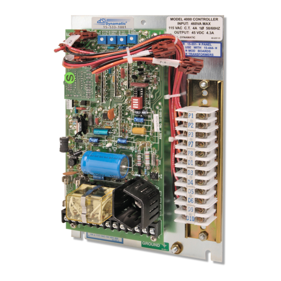
Table 2-2 Panel Mounted 4000 Controllers Model 4000 Final Mod. Pos 1. Pos. 2. Pos. 3 Pos. 4 Pos. 5 Options Controller Type Assembly Board Basic Speed Control 15-533-1001 Stop Start Fixed Brake Speed Linear Accel Speed w Adj Brake 15-533-1002 15-44-4 Stop... -
Page 16: Table 2-3 Panel Mounted 4050 Controllers
Table 2-3 Panel Mounted 4050 Controllers Model 4050 Final Mod. Pos 1. Pos. 2. Pos. 3 Pos. 4 Pos. 5 Options Controller Type Assembly Board Basic Speed Control 15-539-0001 Stop Start Fixed Brake Speed Linear Accel Speed w Adj Brake... - Page 17 Table 2-4 NEMA 13 Enclosure 4050 Controllers Model 4050 Final Mod. Pos 1. Pos. 2. Pos. 3 Pos. 4 Pos. 5 Options Controller Type Assembly Board Basic Speed Control 15-553-0001 Stop Start Fixed Brake Speed Linear Accel Speed w Adj Brake...
-
Page 18: Section 3
12 available modification boards that make up the 4000 and 4050 system. If you have purchased a complete controller, this section can be passed over and you may proceed with the next section, covering installation. -
Page 19: Modification Pcb
Modification PCB When a modification PCB assembly is required, we suggest you install this board according to the following procedure: 1. Place the main PCB in front of you with the long dimension in a horizontal position and the terminal strip to the left. 2. -
Page 20: Wiring
Wiring In the standard NEMA 13 version, with the operator’s control elements mounted in the door, the operator’s elements are completely wired. Wiring of the operator’s elements to the panel mount version of the controller is through a 12-position terminal block, located on the right side of the panel. All connections to this terminal block must be wired as shown on the connection diagram. -
Page 21: Section 4
Dynamatic sales representative. Mounting Panel Mounted Model 4000 and 4050 Controllers The Model 4000 and 4050 panel mount controllers should be mounted with the main PCB terminal block toward the bottom of your enclosure. The minimum depth required for the controller is 4”. -
Page 22: Mounting An Input Transformer
Controller input wiring should be sized to carry 115 Vac at 4 amps for the 4000 controller and 7 amps for the 4050 controllers. The dc output to the coils is 45 Vdc at 8 amps for Model 4050 controllers and 45 Vdc at 4.3 amps for Model 4000 controllers. -
Page 23: Programming Dip Switch
pair of conductors having a continuous metallic shield around the twisted pair with an insulating jacket over the shield. At the generator and indicator ends, cut back the shield as required to expose enough lead to make the connection, Then, tape the exposed shield so that it does not ground at that point. On the controller panel, strip off enough of the outer jacket to expose several inches of shield, Unwrap or unbraid the shield ground connection cannot make contact with the terminals at the terminal strip. - Page 24 The main PCB assembly uses to Dip switch (SW 1) in all cases where no modification PCB assembly is used. When looking at the board, with the terminal block to the left, you will see a 4 pole, 8 pin switch plugged into the left half of the receptacle (RECP1).
-
Page 25: Section 5
Section 5 Operation The Model 4000 and 4050 controllers are easy to operate. However, a more detailed knowledge of the controller’s functions will help you obtain the best possible performance. Knowing now they work will help you trouble shoot any problems that may arise. Before applying power to the controller please read these operating instructions carefully. -
Page 26: Linear Acceleration Option
This type of controller is frequently used with a take-up or spooler drive where voltage (torque) is proportional to web tension and speed varies with the diameter of the roll A block diagram for the basic speed controller version of the Model 4000 and 4050 is shown in Figure 5-2. -
Page 27: Fixed Brake Option
When the controller is stopped, the E relay de-energizes, connecting the brake coil to terminals B1 and B2. The 4050 controller is capable pf putting out 45 Vdc, 8 amps continuous at these terminals. The 4000 controller is capable of 4.3 amps continuous at this voltage. An electrically applied brake is required, such as the eddy current brake or electromagnetic friction brake. -
Page 28: Spring Set Brake Option
Spring Set Brake Option All Model 4000 and 4050 controller configurations provide a normally open (NO) relay contact from the E relay, wired to terminals D7 and D8. This contact is open whenever the controller is stopped and is rated 115 Vac or 24 Vdc, 5 amps resistive load, 150 VA pilot duty. If a spring set brake is not used the E relay contact is available for any customer use within its rating. -
Page 29: Tach Follower Modification, 15-444-1
The Low Signal Follower modification circuit accepts a transducer output signal (current or voltage) and conditions it to produce a dc reference voltage for the Model 4000 and 4050 controllers. The circuit is adjusted so that a specific linear drive speed range is obtained for a given transducer output range. -
Page 30: Torque Limit Modification, 15-444-2
Difference Amplifier. When it exceeds the Torque Limit reference, a negative feedback signal is sent to the Model 4000 and 4050 controllers. The controller is “phased” back to the point where the clutch excitation is such that the torque reflected to the motor remains at the pre-set value of Torque Limit potentiometer R19 located on the modification PCB. -
Page 31: Figure 5-3: Model 4000 Controller Schematic With 15-530-5 Main Assembly
Figure 5-3: Model 4000 Controller Schematic with 15-530-5 Main Assembly Page | 31... -
Page 32: Figure 5-4: Model 4050 Controller Schematic With 15-530-6 Main Pcb Assembly
Figure 5-4: Model 4050 Controller Schematic with 15-530-6 Main PCB Assembly Page | 32... -
Page 33: Mutuatrol® Modification, 15-446-2
This modification circuit accepts and translates an air pressure input signal into a voltage reference for the Model 4000 and 4050 controllers. The circuit is designed to provide the full output speed range with a 0 to 15 psi input air signal for PCB 15-444-3, and 0 to 30 psi input air signal for PCB 15-446-102. -
Page 34: Section 6
Section 6 Start-Up and Adjustments This section of the manual is intended to assist you in placing Model 4000 or 4050 controllers into service. Before turning on the power please read these instructions carefully. Although the controller has been tested and inspected at the factory the following series of Power Off tests must be completed before turning power on to the controller. -
Page 35: Tools Required
*On the Model 4000 controller: 15-533-10** is the assembly number for panel assembly controller. 15- 551-10** is the assembly number for NEMA 13 Enclosure Controls. **On the Model 4050 controller: 15-539-00** is the assembly number for panel assembly controllers. 15-553-00** is the assembly number for NEMA 13 Enclosure Controls. -
Page 36: Power On Tests
5. Disconnect the clutch (C1 & C2) and brake (B1 & B2) leads from the controller terminal strip. Using an ohmmeter, check resistance between each lead and ground, and all other leads for shorts. If a brake is not used, check to ensure that the leads are not inadvertently shorting out inside of the drive. -
Page 37: Set-Up Of Main Pcb Assembly
Set-Up of Main PCB Assembly This procedure is applicable to all Model 4000 and 4050 controllers. After reading this section, refer to the Instruction Sheet for your controller and follow the steps in the order provided. In each case the objective is to adjust the main PCB assembly first and then set up any modification that may be used. -
Page 38: Led Set-Up
Fractional Hp (FHP) FHP/181/182 184/186/214 14/18/112/132/140/180 15% 216/254/253/280 21/160/210 320/360/440 25/27/180/225/250/280 100% Set the Current Feedback potentiometer R20 to 0% (Full CCW) g. Set the programming switches and jumper as indicated in the controller programming chart on the connection diagram *Typical product number stamped on mechanical unit nameplate: 1. -
Page 39: Max Speed/Volts R21
turning. Stop and start the controller a few times to be sure the drive shaft does not rotate. b. For a minimum speed greater than zero, the LED cannot be used. Turn the Zero Adjust potentiometer CW until the desired speed is obtained. For an accurate setting use a tachometer or stroboscope. -
Page 40: Time Constant (Tc) Adjust R26
30 hp for the 4000 controller and up to 200 hp for the 4050 controller. Set your TC Control appropriately for your individual drive size, as shown in the Preliminary adjustments on page 33. -
Page 41: Velocity Damping R22
Velocity Damping R22- Velocity damping is the main type of damping used on the Model 4000 and 4050 controllers. This damping signal is derived from the speed feedback (governor generator) voltage is a dc voltage that functions primarily as the negative feedback signal. -
Page 42: Current Feedback, R20
J1 from the normal to the Increased position. J1 is located near the top of the main Model 4000 or 4050 printed circuit board. *The Current Feedback is a derivative signal, not a direct, proportional feedback signal. -
Page 43: Basic Torque Control (Used When Speed Control Is Not Used)
Basic Torque Control (Used when speed control is not used) It is important to note that 100% torque is not 100% clutch coil voltage, as that amount of excitation will always overload the drive motor. Set maximum torque to not exceed full load motor current. Refer to IS-000539-0012A, for the Basic Torque Control set-up procedure. -
Page 44: Section 7
Maintenance and Trouble Shooting Maintenance Very little maintenance is required to keep the Model 4000 and 4050 controllers in service. Periodically, we suggest that you check the controller to make sure all terminal screws and other connections are tight. Look for signs of trouble, such as burn spots on the boards, loose parts, worn out switches or pushbuttons and any other abnormal condition. -
Page 45: If The Drive Runs At Full Speed
1. With ac power removed, set your multimeter on the 250 Vac range. Measure controller terminals X1 and X2. With power, OFF you should read zero volts. Do not proceed until a zero reading is obtained. Then pull fuses FU1 and FU2 (main PCB assembly) and check for blown fuses. -
Page 46: Renewal Parts And Service
If no external cause is found, replace the main PCB assembly. Renewal Parts and Service Renewal parts for the Model 4000 and 4050 controllers are stocked by Dynamatic. We suggest you stock renewal parts to minimize down time. You alone can evaluate the cost of down time compared to the cost of stocking spares. - Page 47 Drive Source International Dynamatic 7900 Durand Avenue, Bldg 3 Sturtevant, WI USA 53177 Toll Free: 800-548-2169 Phone: 262-554-7977 Email: sales@dynamatic.com Website: dynamatic.com Page | 47...
Need help?
Do you have a question about the 4050 and is the answer not in the manual?
Questions and answers