Dynamatic 4000 Instruction Manual
Stamping press controllers
Hide thumbs
Also See for 4000:
- Instruction sheet (14 pages) ,
- Instruction manual (47 pages) ,
- Instruction sheet (13 pages)
Table of Contents
Advertisement
Quick Links
Advertisement
Table of Contents
Troubleshooting

Related Manuals for Dynamatic 4000


Summary of Contents for Dynamatic 4000
- Page 1 Model 4000 and 4050 Stamping Press Controllers Instruction Manual Part Number IM-110005-8404 7900 Durand Avenue, Bldg 3 Sturtevant, WI USA 53177 Toll Free: 800-548-2169 Phone: 262-554-7977 Email: sales@dynamatic.com Website: dynamatic.com Page | 1...
- Page 2 Please Observe the Following Safety Guidelines Allow Installation and Service by Qualified Personnel Only: Electrical rotating equipment and associated controls can be dangerous. Therefore, it is essential that only trained personnel be allowed to work with this equipment, under competent supervision. The danger is when the equipment is not handled, installed, maintained or used properly.
- Page 3 PRO/Serial number as pertaining to specific piece of equipment take precedence over this manual. Note: The information furnished may not cover changes made to the equipment after shipment. All data is subject to change without notice. Technical Assistance: Please contact Dynamatic at 1-800-548-2169 or 262-554-7977 Page | 3...
-
Page 4: Table Of Contents
Table 2-1 Specifications ..................... 10 Basic Controller Assembly ...................... 11 Table 2-2 Panel Mount 4050 Controllers with a Transformer ........... 12 Drive Description and Application ..................12 Model 4000-4050 Comparison ....................13 Installation ..........................13 Operation ..........................13 Start-up and Adjustments ...................... 13 Figure 2-1 Stamping Press Controller 15-541-000* with torque Limit, Speed Trip, and Minimum Adjustment Panel Outline Mounting Dimensions............ - Page 5 Modification PCB ........................19 Figure 3-2 Modification PCB Standoff ................19 Wiring ............................. 20 Programming Dip Switch ....................... 21 Figure 3-3 Dip Switch Installation & Programming ............21 Figure 3-4a Connection Diagram Model 4050 Stamping Press Controller with Torque Limit, Speed Trip and Minimum Speed Adjustment 115V, 208V, 390V, 230/460V or 575V Input and 8.0 Adc Output (15-541-*) .......................
- Page 6 Section 5 ..................36 Start-Up and Adjustments ......................36 Tools Required ........................36 Power Off Test ........................36 Power On Test ........................37 Set-Up Main PCB Assembly ....................38 Preliminary Adjustments ....................... 38 Figure 5-1 Trimpot Illustration ................... 39 Basic Speed Control (without Torque Limit) ................40 LED Set-Up ..........................
-
Page 7: Section 1
While every effort has been made to provide a complete and accurate manual, there is no substitute for trained, qualified personnel to handle unusual situations. If any questions arise regarding the operation or maintenance of this controller, please refer them immediately to Dynamatic Customer Service at 1-800-548-2169 or 262-554-7977. -
Page 8: Receiving And Damage Claims
File a claim immediately with the carrier if any damage or loss is found. Should you require assistance in settling your claim with the carrier, contact Dynamatic. You will need the unit model number, serial number and your purchase order number for identification. -
Page 9: Removal From Storage
These are not manufacturer’s defects and will not be covered by the warranty policy. Refer questions to the Field Service Department in Sturtevant Wisconsin. Removal from Storage Before returning the controller to service after long time storage, it will be necessary to carefully inspect it for any signs of damage or deterioration. -
Page 10: Section 2
Model 4050 stamping press controllers have been extended to approximately twice that of the original Model 4000 controller. Current feedback damping is available for customers who require this type of response. The output of each controller is short circuit proof, which includes the following conditions: 1. -
Page 11: Basic Controller Assembly
2. Shorting of terminal B1 to B2 3. Shorting of terminals C1 or C2 to earth ground 4. Shorting of terminals B1 or B2 to earth ground If any of these events occur, the controller shall be completely self-protecting without damage to any of its internal components. -
Page 12: Drive Description And Application
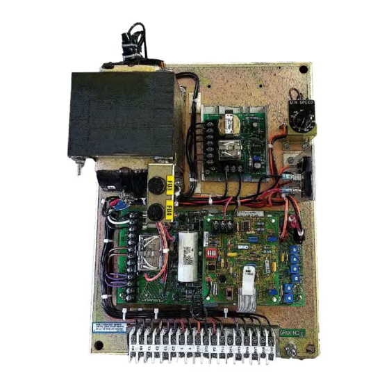
Mounting of the 15.12” x 11.38” transformer mount panel is by means of the four corner holes provided. See Figures 2-1 and 2-2 for mounting dimensions and depth requirements. Requirements. Components included on each panel are as follows: main PCB1, 15-530-6; modification PCB2, 15-444-2; T1 transformer;... -
Page 13: Model 4000-4050 Comparison
The primary difference is the 4050 heatsink, HR1, with the power semiconductors. On the Model 4000 these semiconductors (D1, D2, and Q1) are mounted on the main PCB assembly so the off-board heatsink is not required. - Page 14 Figure 2-1 Stamping Press Controller 15-541-000* with torque Limit, Speed Trip, and Minimum Adjustment Panel Outline Mounting Dimensions Page | 14...
-
Page 15: Adjustment (W/O Speed Trip) Panel Outline Mounting Dimensions
Figure 2-2 Stamping Press Controller 15-541-002* with Torque Limit Minimum Speed Adjustment (w/o Speed Trip) Panel Outline Mounting Dimensions Page | 15... - Page 16 Figure 2-3 Stamping Press Controller 15-539-0019 with Torque Limit and Minimum Speed Adjustment Panel Outline Mounting Dimensions Page | 16...
- Page 17 Figure 2-4 Stamping Press Controller 15-539-0020 with Torque Limit and Minimum Speed Adjustment Panel Outline Mounting Dimensions (Typical Layout/Subject to Change) Page | 17...
-
Page 18: Section 3
Section 3 Installation Mounting Panel Mounted Controllers The Model 4050 panel mount stamping press controllers should be mounted with the main PCB/panel terminal block toward the bottom of your enclosure. The minimum depth required for the controller is wither 4” or 8” (refer to the panel outline mounting dimension drawings in figures 2-1 through 2-4 for your specific models) You may use the controller as a template or use the appropriate outline mounting drawing to locate the required mounting holes. -
Page 19: Main Printed Circuit Board Support
Main Printed Circuit Board Support If it is necessary to install the main PCB 15-530-6 onto the panel, the following instructions are provided to help you with this task. Position the board so that it is supported by each of the two support brackets. Then mount the printed circuit board to the panel with the four mounting screws that are furnished. -
Page 20: Wiring
The minimum requirements are specified in the National Electrical Code; other local regulations may also apply. If a question exists, consult Dynamatic 800-548-2169. Wire size, number of conductors in a conduit or raceway and grounding are also specified by the National Electrical Code and other applicable local regulations. -
Page 21: Programming Dip Switch
C1 at the controller. A screwdriver with a blade width not exceeding 1/8” should be used to loosen each terminal screw. When the terminal screw is tight, back it out four (4) full turns. Route the conductor neatly to the terminal, mark the length at a point that just reaches the back-insulating barrier, cut off and then strip it to expose 5/16”. -
Page 22: And 8.0 Adc Output (15-541-*)
Figure 3-4a Connection Diagram Model 4050 Stamping Press Controller with Torque Limit, Speed Trip and Minimum Speed Adjustment 115V, 208V, 390V, 230/460V or 575V Input and 8.0 Adc Output (15- 541-*) 53831 Page | 22... - Page 23 Figure 3-4b Schematic Diagram for Model 4050 Stamping Press Controller (15-541-*) continued… 53831 Model 4050 Stamping Press Controller with Torque Limit, Speed Trip and Minimum Speed Adjustment 115V, 208V, 390V, 230/460V or 575V Input and 8.0 Adc Output (15-541-*) *15-541-0001, 15-541-0002, 15-541-0003, 15-541-0004, 15-541-0005 Page | 23...
-
Page 24: Speed Trip And Minimum Speed Adjustment 208/230/460V Input And 5.5 Adc Output (15-541- 0007)
Figure 3-5a Connection Diagram for 4050 Stamping Press Controller with Torque Limit. Speed Trip and Minimum Speed Adjustment 208/230/460V Input and 5.5 Adc Output (15-541-0007) 56832 Page | 24... - Page 25 Figure 3-5b Schematic Diagram for 4050 Stamping Press Controller with Torque Limit continue 56832 4050 Stamping Press Controller with Torque Limit. Speed Trip and Minimum Speed Adjustment 208/230/460V Input and 5.5 Adc Output (15-541-0007) Page | 25...
-
Page 26: Input And 8.0 Adc Output (15-451-002*)
Figure 3-6a Connection Diagram for 4050 Stamping Press Controller with Torque Limit and Minimum Speed Adjustment (without Speed Trip) 115V, 208V, 390V, 230/460V or 575V Input and 8.0 Adc Output (15-451-002*) 56836 Page | 26... - Page 27 Figure 3-6b Schematic Diagram for 4050 Stamping Press Controller (15-451-002*) continued… 53836 Model 4050 Stamping Press Controller with Torque Limit and Minimum Speed Adjustment (without Speed Trip) 115V, 208V, 390V, 230/460V or 575V Input and 8.0 Adc Output (15-451-002*) *15-541-0021, 15-541-0022, 15-541-0023, 15-541-0024, 15-541-0025 Page | 27...
- Page 28 Figure 3-7a Connection Diagram for Model 4050 Stamping Press Controller with Torque and Minimum Speed Adjustment 115V input and 8 Adc. Output (15-539-0019) 56819 Page | 28...
- Page 29 Figure 3-7b Schematic Diagram for Model 4050 Stamping Press Controller (15-539-0019) continued… (Model 4000 is the same except 15-530-5 PCB Assembly is used. PCB assembly includes items shown here as 15-529-19 heatsink assembly) 56819 Model 4000 Stamping Press Controller with Torque Limit and Minimum Speed Adjustment 115V input and 4.3 Adc output (15-533-1019)
- Page 30 Adjustment (without Torque Limit) 115 V input and 8 Adv output (15-539-0020) 56820 Model 4000 Stamping Press Controller with minimum Speed Adjustment (without Torque Limit) 115 V input and 4.3 Adc output (15-533-1020) Model 4050 Stamping Press Controller with minimum Speed Adjustment (without Torque Limit) 115 V...
- Page 31 Figure 3-8b Schematic Diagram for Model 4050 Stamping Press Controller (15-539-0020) continued (Model 4000 is the same except 15-530-5 PCB assembly is used. PCB assembly includes items shown here is 15-529-19 heatsink assembly 56820 Model 4000 Stamping Press Controller with Torque Limit and Minimum Speed Adjustment 115V input and 4.3 Adc output (15-533-1020)
-
Page 32: Section 4
Section 4 Operation The Model 4050 stamping press controllers are easy to operate. However, a more detailed knowledge of the controller’s functions will help you obtain the vest possible performance. Knowing how they work will help you trouble shoot any problems that may arise. Before applying power to the controller please read these operating instructions carefully. -
Page 33: Torque Limit Modification 15-44-2
Any sudden load change would change the drive speed, change feedback voltage, increase the error signal and result in a change in drive excitation to correct for the load change. In actual operation, the voltage across the clutch coil is constantly varying to compensate for loads changes. The Model 4050 stamping press controllers are somewhat more complex than the preceding explanation, in that two feedback loops are connected. -
Page 34: Fixed Brake Option
easily connected or disconnected by the Dip switch or by closing SW2 on the modification board. With the switch open, acceleration is limited only by the torque limit circuit. The purpose of linear acceleration is to slow down response to a change in command. Without linear acceleration control, the drive will respond to operator speed adjustments very quickly, limited only by the torque capacity of the drive. - Page 35 Figure 4-2 Model 4050 Controller Block Diagram Page | 35...
-
Page 36: Section 5
Section 5 Start-Up and Adjustments This section of the manual is intended to assist you in placing your Model 4050 stamping press controllers into service. Before turning the power ON please read these instructions carefully. Although the controller has been tested and inspected at the factory the following series of Power Off test must be completed before turning power to the controller ON. -
Page 37: Power On Test
5. Disconnect the clutch (C1 & C2) and brake (B1 & B2) leads from the controller terminal strip. Using an ohmmeter, check resistance between each lead and ground, and all other leads for shorts. If a brake is not used, check to ensure that the leads are not inadvertently shorting out inside of the drive. -
Page 38: Set-Up Main Pcb Assembly
6. Checkout the operation of the machine before making any controller adjustments. Turn up the Run Speed potentiometer and run the machine at some safe, reasonable speed. Carefully check all parts of the machine to make sure it is functioning properly and that it is safe to continue. Stop the drive, turn OFF the ac power and make any connections that are necessary. - Page 39 AC/ACM/ACS/PD/VT AS/AT/AE/VT/EC Fractional Hp (FHP) Fractional Hp 14/112/140 181/182/184/186 18/21/132/160/180/210 214/216/254/256 25/27/180/225/250/280 280/320/360/440 Mechanical Unit Model Numbers Velocity Damping Setting AC/ACM/ACS/PD/VT AS/AT/AE/VT/EC Fractional Hp (FHP) FHP/181/182 184/186/214 14/18/112/132/140/180 216/254/256/280 21/160/210 320/360/440 25/27/180/225/250/280 100% *Typical product number stamped on mechanical unit nameplate: 1.
-
Page 40: Basic Speed Control (Without Torque Limit)
a. Set the Torque Limit Damping potentiometer R18 at 50% CW. b. Set the Torque Limit potentiometer R19 at 50% CW (this setting is approximately 150% of rated motor torque) c. Set HI Damping potentiometer R20 to 0% (Full CCW) d. -
Page 41: Max Speed/Volts R21, Alternate Methods
b. For a minimum speed greater than zero, the LED cannot be used. Turn the Zero Adjust potentiometer CW until the desired speed is obtained. For an accurate setting use a tachometer or stroboscope. 5. MAX SPEED/Volts R21- this adjustment can be set to limit drive speed to its rated maximum or to a slower speed as required by the machine process. - Page 42 6. Since there may be some interaction between the Zero Adjust and the Max Speed/Volts, particularly if the minimum speed is other than zero, repeat steps 4 and 5 until the desired speeds are obtained for both the zero and maximum positions of the Run Speed pot. 7.
-
Page 43: Control With Torque Limit Modification
The Velocity Damping setting specified under Preliminary Adjustments is a good starting point and will result in satisfactory performance for most applications. This pot is used to match the controller’s response to the drive’s response (drive response is a function of the clutch coil time constant and the system inertia). - Page 44 range that the HI Damping pot R20 has on the modification board. However, they may be used in combination on high inertia applications where increased damping is required. 13. Torque Limit PCB 15-444-2 (normal Load) a. Apply the normal load to the drive. b.
-
Page 45: Section 6
Look for signs of trouble, such as burn spots on the boards, loose parts, worn out switches or pushbuttons and any other abnormal condition. Correct any deficiency found. If you have a question, consult Dynamatic at 800-548-2169. The relays in the controller have a definite life, as do the potentiometers and switches. They are designed for many years of average use, but your operation may call for more frequent switching. -
Page 46: Troubleshooting
Troubleshooting The possibility of component failures or other problems always exists. This section of the manual is provided to assist you in finding the fault and making repairs. Our design philosophy is based on assembly replacement. Trying to find a failed part on a printed circuit board is not economical when you compare the cost of labor and down time with the cost of a replacement PCB assembly. -
Page 47: Renewal Parts And Service
PCB assembly. Renewal Parts and Service Renewal parts for the Model 4050 stamping press controllers are stocked at Dynamatic. We suggest you stock renewal parts to minimize down time. You alone can evaluate the cost of down time compared to the cost of stocking spares. -
Page 48: Renewal Parts List
Warranty controller failure will be handled by replacements. Technical assistance is always available over the telephone, and field service engineers are available for start-up, trouble shooting and training seminars at the published rates. Contact Dynamatic 262-554-7977. The company maintains a Repair Service Department the works on a time and material basis. Controllers returned under Warranty for repair will be repaired and returned with the original unexpired warranty agreement continuing to be in effect. - Page 49 4050 Stamping Press Controller with a Transformer and Torque Limit (Less Trip Circuit) 15-541-0021 through -0025 Panel Assembly ** Part Number Description Legend 15-530-0006 Main PCB (refer to PCB parts list Above) 15-444-0002 Torque Limit PCB assembly 15-529-0021 Heatsink assembly, including Q1 & D3 15-541-0021 Panel Mount with Transformer for 115 Volt Input 64-361-0008 1kVA transformer, 50/60 Hz., 115 V Sec.
- Page 50 53-398-0001 Relay, 4pdt, plug-in 15-533-1019 Panel Mount with Torque Limit 15-530-0005 Main PCB Assembly (Refer to PCB parts list above) 15-444-0002 Torque Limit PCB assembly 36-298-0010 Circuit board support 15-533-1020 Panel Mount with Minimum Speed (Less Torque Limit) 15-530-0005 Main PCB assembly (Refer to PCB parts list above) 36-298-0010 Circuit Board support *Denotes minimum spare parts...
-
Page 51: Loose Parts For 4050 Stamping Press Controller
Loose Parts for 4050 Stamping Press Controller Page | 51... - Page 52 Drive Source International Dynamatic 7900 Durand Avenue, Bldg 3 Sturtevant, WI USA 53177 Toll Free: 800-548-2169 Phone: 262-554-7977 Email: sales@dynamatic.com Website: dynamatic.com Page | 52...
Need help?
Do you have a question about the 4000 and is the answer not in the manual?
Questions and answers
what is the DY8 and DY(9 circuit