Dynamatic 4000 Instruction Sheet
Hide thumbs
Also See for 4000:
- Instruction manual (52 pages) ,
- Instruction sheet (14 pages) ,
- Instruction sheet (13 pages)
Table of Contents
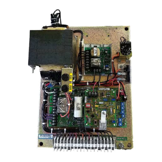
Advertisement
Instruction Sheet
IS-539-14
revised 2019
15-533-1014 Panel Mount 4000 (4.3 A Controller)
15-535-1014 Standard Enclosure 4000 (4.3 A Controller)
15-539-0014 Panel Mount 4050 (8 A Controller)
15-540-0014 Standard Enclosure 4050 (8 A Controller)
Model 4000 and 4050 with Torque Speed
Introduction:
These instructions relate specifically to the
following Model 4000 and 4050 controllers
which are assembled for Speed Control with
the Torque Limit Modification.
Connection diagram, schematic diagram,
switch
programming,
connection, adjustment procedure and
recommended spare parts list for these
specific assemblies are contained in this
instruction sheet. Any differences between
these two controllers are clearly noted.
Use instruction manual IM-13006-83XX with
this
instruction
and
instructions.
Caution: Above ground electrical potentials
can be hazardous. Always disconnect
electrical power before working on the
controller.
*Heat sink assembly, HS1, and its wiring
apply only to the Model 4050 controllers.
These parts are not supplied on Model 4000
controllers. The parts are mounted on the
15-530-5 main 4000 board.
1
plug
wiring
maintenance
Drive Source International/Dynamatic
7900 Durand Ave Bldg 3 Sturtevant, WI 53177
sales@dynamatic.com
800-548-2169 •
www.Dynamatic.com
15-539-14
Advertisement
Table of Contents

Related Manuals for Dynamatic 4000


Summary of Contents for Dynamatic 4000
-
Page 1: Introduction
*Heat sink assembly, HS1, and its wiring apply only to the Model 4050 controllers. These parts are not supplied on Model 4000 controllers. The parts are mounted on the 15-530-5 main 4000 board. -
Page 2: Table Of Contents
Introduction: Connection Diagram for Standard Enclosure 4000 Controller Schematic Diagram for 4000 Controller Connection Diagram for 4000 Panel Mount and 4050 Controllers Schematic Diagram for 4050 Controller Torque Limit Modification PCB 15-444-2 Modification PCB Mounting General Description Preliminary Adjustments Main PCB 15-530-5 or 15-530-6... -
Page 3: Connection Diagram For Standard Enclosure 4000 Controller
Connection Diagram for Standard Enclosure 4000 Controller ED-58214/A Note 1: This equipment must be installed in compliance with national electrical code and all applicable state and local codes. Note 2: Transformer may be supplied as a winding in the ac motor or as a separate item. -
Page 4: Schematic Diagram For 4000 Controller
Schematic Diagram for 4000 Controller... -
Page 5: Connection Diagram For 4000 Panel Mount And 4050 Controllers
Connection Diagram for 4000 Panel Mount and 4050 Controllers ED-56814/A *See page three for notes and description of symbols... -
Page 6: Schematic Diagram For 4050 Controller
Schematic Diagram for 4050 Controller... -
Page 7: Torque Limit Modification Pcb 15-444-2
Torque Limit Modification PCB 15-444-2 Modification PCB Mounting If you have purchased a complete controller this section may be passed over and you may proceed to General Description. 1. Place the Main PCB in front of you with the long dimension in a horizontal position and the terminal strip to the left. -
Page 8: Preliminary Adjustments
maximum value. This limit can be used to prevent the motor breakover torque from being reached during a condition such as drive output shaft “lock-up” or the period when a large system inertia is being accelerated. The adjustment range is from 50 to 150% of rated motor torque. Preliminary Adjustments Perform the following preliminary adjustments (with no power applied to the controller) 1. -
Page 9: Adjustment Procedure
Caution: To avoid personal injury or damage to the test equipment remove power before connecting ok disconnection test equipment The Model 4000 and 4050 controllers contain an LED status monitor which provides a visual means of setting the maximum speed and zero adjust. This LED set up along with an alternate method is given below. -
Page 10: Max Speed/Volts R21, Alternate Methods
A trimpot illustration is provided to facilitate the setting of this control. Sufficient range has been provided for drive sizes from fractional though 20 hp for the 4000 controller and up to 125 hp for the 4050 controller. Set your TC control appropriately for your individual drive size as shown in Preliminary Adjustments. -
Page 11: Accel Rate R18
Increased position. Adjust current feedback R20 as required to obtain desired drive response. *See basic 4000/4050 manual for a more detailed description of this adjustment. R18- The purpose of Linear Acceleration is to slow down drive response to an increase Accel Rate in command. - Page 12 b. Monitor the motor current. Since current is proportional to torque, check your nameplate for the rated motor current to determine to desired torque limit. Example- If your drive is rated at 10 amps, and you want to limit the torque (150% of 10 amperes is 15 amperes), start the drive and note the maximum current on the ac ammeter during acceleration.
-
Page 13: Renewal Parts List
Renewal Parts List for Standard 4000 & 4050 Controllers with Torque Speed Part Number Description Legend Model 4000 Controllers 15-530-0005 Main PCB Assembly ** 27-123-0001 Mini-Jumper 32-018-4091 Fuse, 4 Amp, 250 V FU1, 2 53-398-0001 Relay, 4pdt, plug-in 15-533-1014 Panel Mount... - Page 14 Drive Source International/Dynamatic 7900 Durand Ave Bldg 3 Sturtevant, WI 53177 800-548-2169 •sales@dynamatic.com www.Dynamatic.com...
Need help?
Do you have a question about the 4000 and is the answer not in the manual?
Questions and answers