Table of Contents
Advertisement
Quick Links
Advertisement
Table of Contents

Related Manuals for Supermicro SuperBlade SBA-4119SG


Summary of Contents for Supermicro SuperBlade SBA-4119SG
- Page 1 SuperBlade Server SBA-4119SG USER’S MANUAL Revision 1.0...
- Page 2 State of California, USA. The State of California, County of Santa Clara shall be the exclusive venue for the resolution of any such disputes. Supermicro's total liability for all claims will not exceed the price paid for the hardware product.
- Page 3 If you have any questions, please contact our support team at: support@supermicro.com This manual may be periodically updated without notice. Please check the Supermicro website for possible updates to the manual revision level. Secure Data Deletion A secure data deletion tool designed to fully erase all data from storage devices can be found on our website: https://www.supermicro.com/about/policies/disclaimer.cfm?url=/wftp/utility/...
-
Page 4: Table Of Contents
SuperBlade Server SBA-4119SG User's Manual Contents Chapter 1 Introduction 1.1 Overview ..........................7 Eligible Enclosures ......................7 1.2 System Features ........................8 1.3 Control Panel ........................9 1.4 Front View ..........................10 1.5 Components ........................11 1.6 System Block Diagram .......................13 Chapter 2 Installation and Setup 2.1 Unpacking the System .......................14 2.2 Installing or Accessing the Blade Unit ................15 Installing a Blade Unit into the Enclosure .................15... - Page 5 Contents Chapter 3 Management and Maintenance 3.1 Management Software ......................34 IPMI ...........................34 BMC ADMIN User Password ..................34 3.2 SuperDoctor 5 ........................35 ® 3.3 Motherboard Battery ......................36 3.4 System Cooling ........................37 Installing the Air Shrouds ....................37 Checking the Server Air Flow ...................38 Overheating ........................38 3.5 Where to Get Replacement Components ................39 3.6 Returning Merchandise for Service ..................39...
- Page 6 Super Micro Computer, Inc. 980 Rock Ave. San Jose, CA 95131 U.S.A. Tel: +1 (408) 503-8000 Fax: +1 (408) 503-8008 Email: marketing@supermicro.com (General Information) support@supermicro.com (Technical Support) Website: www.supermicro.com Europe Address: Super Micro Computer B.V. Het Sterrenbeeld 28, 5215 ML...
-
Page 7: Chapter 1 Introduction
Chapter 1: Introduction Chapter 1 Introduction 1.1 Overview The SBA-4119SG blade is a compact self-contained server that connects into a pre-cabled enclosure that provides power, cooling, management and networking functions. One enclosure can hold up to twenty blades. Each blade contains one computing node. In this manual, “blade”... -
Page 8: System Features
System Features Motherboard BH12SSi-M25 Single AMD EPYC 7002 Series processor (in Socket SP3); For the latest CPU/memory updates, refer to our website at Supermicro.com Chipset System on Chip Memory Eight slots for up to 2 TB of 3DS RDIMM/LRDIMM), with speeds of up to 3200 MHz; support for Non-Volatile... -
Page 9: Control Panel
Chapter 1: Introduction 1.3 Control Panel Power switches and status LEDs are located on the control panel on the front of the chassis. Figure 1-1. Control Panel Control Panel Features Item Feature State Description The main power switch applies or removes primary power from the Power button power supply to the server but maintains standby power. -
Page 10: Front View
SuperBlade Server SBA-4119SG User's Manual 1.4 Front View The illustration below shows the features on the front of the blade unit. Figure 1-2. Front View Chassis Front Features Item Features Description Control Panel Power button and status indicators Service/Asset Pull-out identifier (with BMC ADMIN default password sticker) BMC Password Sticker Figure 1-3. -
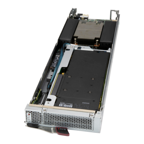
Page 11: Components
Chapter 1: Introduction 1.5 Components Figure 1-4. Components Labeled (see the next page) - Page 12 SuperBlade Server SBA-4119SG User's Manual Blade Components Item Feature Description GPU bay Processor and heatsink Memory DIMM slots (under air shrouds) M.2 Slots Slots and standoffs for M.2 storage cards Mezzanine Add-on card Figure 1-5. Exploded View...
-
Page 13: System Block Diagram
Chapter 1: Introduction 1.6 System Block Diagram BH12SSi-M25 AMD SP3 Rev. 1.00 SerDes Backplane Connector 25G x2 BIOS ROM 32MB G2 [18-15] CX4 25G LAN CPU USB2 [2] RTL8211FS TWO PORT AST2500 BMC ROM Mezzanine slot G3 [14] G1 [0-15] 32MB PCIE X16 AMD SP3... -
Page 14: Chapter 2 Installation And Setup
SuperBlade Server SBA-4119SG User's Manual Chapter 2 Installation and Setup This chapter provides instructions on installing and replacing main system components. To prevent compatibility issues, only use components that match the specifications or part numbers. Up to twenty blade modules may be installed into a blade enclosure, depending upon your enclosure and blade. -
Page 15: Installing Or Accessing The Blade Unit
Chapter 2 Installation and Setup 2.2 Installing or Accessing the Blade Unit Installing a Blade Unit into the Enclosure Make sure the cover of the blade unit is on before insertion. Installing a Blade Unit into the Enclosure 1. Pull open the blade locking handle and slowly push the blade into its bay as pictured below. -
Page 16: Removing And Replacing The Blade Cover
SuperBlade Server SBA-4119SG User's Manual Removing and Replacing the Blade Cover The blade cover can be removed to access the mainboard and install processors, memory modules, the onboard battery, etc. • To remove the cover, remove the screws as illustrated below. Slide the cover toward the rear and lift it off. -
Page 17: Powering Up Or Down
Chapter 2 Installation and Setup 2.3 Powering Up or Down Powering Up a Blade Unit Each blade unit may be powered on and off independently from the rest of the blades installed in the same enclosure. A blade unit may be powered up in two ways: •... -
Page 18: Installing The Processor And Heatsink
When receiving a motherboard without a processor pre-installed, make sure that the plastic CPU socket cap is in place and none of the socket pins are bent; otherwise, contact your retailer immediately. • Refer to the SuperMicro web site for updates on CPU support. - Page 19 Chapter 2 Installation and Setup Installing the Processor and Heatsink Begin by removing power from the system as described in Section 2.3. 1. Use a Torx T20 driver to loosen the screws holding down Force Frame in the sequence of 3-2-1. The screws are numbered on the Force Frame next to each screw hole. Tighten to 16.1 kgf-cm (14 lbf-in) of torque.
- Page 20 SuperBlade Server SBA-4119SG User's Manual 2. The spring-loaded Force Frame will raise up after the last screw (#1) is removed. Gently allow it to lift up to its stopping position. Figure 2-4. Raising the Force Frame 3. Lift the Rail Frame up by gripping the lift tabs near the front end of the rail frame. While keeping a secure grip of the Rail Frame, lift it to a position so you can do the next step of removing the External Cap.
- Page 21 Chapter 2 Installation and Setup 4. Remove the External Cap from the Rail Frame by pulling it upwards through the rail guides on the Rail Frame. External Cap PnP Cover Cap Figure 2-6. Removing the External Cap 5. The CPU Package is shipped from the factory with the blue Carrier Frame pre- assembled.
- Page 22 SuperBlade Server SBA-4119SG User's Manual Note: You can only install the CPU inside the socket in one direction with the handle at the top. Make sure that it is properly inserted into the CPU socket before closing the Rail Frame plate.
- Page 23 Chapter 2 Installation and Setup Figure 2-9. Securing the Force Frame 10. Replace the screws in the order 1-2-3, tightening to 16.1 kgf-cm (14 lbf-in) of torque. The Force Frame secures both the Rail Frame and CPU Package. Caution: Tightening must be executed in proper 1-2-3 sequence to avoid causing catastrophic damage to the socket or CPU Package.
- Page 24 SuperBlade Server SBA-4119SG User's Manual 11. Lower the heatsink down till it rests securely on CPU Package over the four screw holes on the socket frame. Figure 2-11. Mounting the Heatsink 12. Using a Torx T20 driver in a diagonal pattern as below, tighten the four heatsink screws halfway and then tighten them evenly to 16.1 kgf-cm (14.0 lbf-in) of torque.
- Page 25 Chapter 2 Installation and Setup Removing a Heatsink We do not recommend removing the heatsink. If necessary, please follow the instructions below to prevent damage to the CPU or the CPU socket. Note: Wait for the heatsink to cool down before removing it. 1.
-
Page 26: Memory
The BH12SSi-M25 supports up to 2TB of 3DS ECC DDR4 3200 MHz speed, RDIMM/ LRDIMM/3DS/NVDIMM memory in eight slots. Refer to the table below for additional memory information. Check the SuperMicro web site for possible updates to memory support. Populating RDIMM/RDIMM 3DS/LRDIMM/LRDIMM 3DS DDR4 Memory Modules Maximum DIMM Capacity (GB) - Page 27 Chapter 2 Installation and Setup MH17 MH15 BAR CODE H12SSW-iN MAC CODE SXB1C JSLIM2 DIMM A1 DIMM H1 DIMM B1 JVRM1 DIMM G1 DIMM C1 DIMM F1 DIMM D1 DIMM E1 FAN4 Figure 2-13. DIMM Numbering FAN3 FAN2 Memory Module Distribution Channel 1 DIMM (Supported, Not Recommended) ü...
-
Page 28: Installing Memory
SuperBlade Server SBA-4119SG User's Manual Installing Memory ESD Precautions Electrostatic Discharge (ESD) can damage electronic com ponents including memory modules. To avoid damaging DIMM modules, it is important to handle them carefully. The following measures are generally sufficient. • Use a grounded wrist strap designed to prevent static discharge. •... -
Page 29: Storage Drives
Chapter 2 Installation and Setup 2.6 Storage Drives The blade supports one internal storage drive, an M.2 solid state drive. M.2 Solid State Drive One M.2 solid state drive (SSD) can be installed, supporting PCIe. Several lengths are supported—42mm, 60mm 80mm or 110mm. For each length, there is an hole in the mounting platform for a plastic clasp. -
Page 30: Installing The Mezzanine Card
SuperBlade Server SBA-4119SG User's Manual 2.7 Installing the Mezzanine Card 1. Install the three standoffs as pictured below. 2. Align the mezzanine card with the connector on the motherboard and slip it in. 3. Secure it with three screws. Figure 2-15. Installing the Mezzanine Card... -
Page 31: Installing The Gpu
Chapter 2 Installation and Setup 2.8 Installing the GPU 1. Remove the power cable and MCIO cables that connect to the motherboard to allow the riser card bracket to be removed. 2. Remove the riser card bracket by removing the four screws the secure it to the chassis. 3. -
Page 32: Driver Installation
The Supermicro website contains drivers and utilities for your system at https://www. supermicro.com/wftp/driver. Some of these must be installed, such as the chipset driver. After accessing the website, go into the CDR_Images (in the parent directory of the above link) and locate the ISO file for your motherboard. -
Page 33: Installing The Operating System
An operating system (OS) must be installed on each blade module. Blades with Microsoft Windows OS and blades with Linux OS can operate within the same blade enclosure. Refer to the SuperMicro web site for a list of supported operating systems. Installing by using PXE Boot Preboot Execution Environment (PXE) is used to boot a computer over a network. -
Page 34: Chapter 3 Management And Maintenance
There are several BIOS settings that are related to IPMI. For general documentation and information on IPMI, visit our website at: http://www.supermicro.com/products/nfo/IPMI.cfm. BMC ADMIN User Password For security, each system is assigned a unique default BMC password for the ADMIN user. -
Page 35: Superdoctor ® 5
3.2 SuperDoctor ® The Supermicro SuperDoctor 5 is a program that functions in a command-line or web-based interface for Windows and Linux operating systems. The program monitors such system health information as CPU temperature, system voltages, system power consumption, fan speed, and provides alerts via email or Simple Network Management Protocol (SNMP). -
Page 36: Motherboard Battery
SuperBlade Server SBA-4119SG User's Manual 3.3 Motherboard Battery The motherboard uses non-volatile memory to retain system information when system power is removed. This memory is powered by a lithium battery residing on the motherboard. Replacing the Battery Begin by removing power from the system as described in section 2.3. 1. -
Page 37: System Cooling
Chapter 3 Management and Maintenance 3.4 System Cooling Installing the Air Shrouds Air shrouds concentrate airflow to maximize fan efficiency. These do not require screws to install. Installing the Air Shrouds • Position the air shrouds as illustrated in the figure below, sliding the front notch over the pin on the fan tray. -
Page 38: Checking The Server Air Flow
SuperBlade Server SBA-4119SG User's Manual Checking the Server Air Flow • Make sure there are no objects to obstruct airflow in and out of the server. • Do not operate the server without drives or drive carriers in the drive bays. •... -
Page 39: Where To Get Replacement Components
(http://www.supermicro.com/ support/rma/). Whenever possible, repack the chassis in the original Supermicro carton, using the original packaging material. If these are no longer available, be sure to pack the chassis securely, using packaging material to surround the chassis so that it does not shift within the carton and become damaged during shipping. -
Page 40: Chapter 4 Motherboard Connections
SuperBlade Server SBA-4119SG User's Manual Chapter 4 Motherboard Connections This section describes the jumpers, connectors, and status LEDs on the motherboard and provides pinout definitions. Depending on how the system is configured, not all connections are required. Please review the Safety Precautions in Appendix B before installing or removing components. -
Page 41: Motherboard Layout
Chapter 4 Motherboard Connections 4.1 Motherboard Layout Below is a layout of the BH12SSi-M25 with jumper, connector and LED locations shown. See the table on the following page for descriptions. 2X M.2 Connectors PCIe Gen 4 or SATA 2X PCIe GEN 4 Connectors PCIe x16 PCIe x16 JPWR1... -
Page 42: Quick Reference
SuperBlade Server SBA-4119SG User's Manual Quick Reference Jumper Description Default Setting JDBG1 Debug Mode Pins 1-2 (Enabled) JBT1 Clear CMOS Open (Normal) JWD1 Watch Dog Timer control Pins 1-2 (Reset) JPG1 Onboard Video Disable/Enable Pins 1-2 (Enabled) Connector Description External speaker/buzzer connector JCPLD1 Complex-Programmable Logical Device (CPLD) header JKVM1... -
Page 43: Headers And Connectors
The JTPM1 header is used to connect a Trusted Platform Module (TPM)/Port 80, which is available from Supermicro. A TPM/Port 80 connector is a security device that supports encryption and authentication in hard drives. It allows the motherboard to deny access if the TPM associated with the storage drive is not installed in the system. -
Page 44: Jumpers
SuperBlade Server SBA-4119SG User's Manual 4.3 Jumpers To modify the operation of the motherboard, jumpers are used to choose between optional settings. Jumpers create shorts between two pins to change the function associated with it. Pin 1 is identified with a square solder pad on the printed circuit board. See the motherboard layout page for jumper locations. - Page 45 Chapter 4 Motherboard Connections Watch Dog (JWD1) JWD1 controls the Watch Dog function. Watch Dog is a monitor that can reboot the system when a software application hangs. Jumping pins 1-2 will cause Watch Dog to reset the system if an application hangs. Jumping pins 2-3 will generate a non-maskable interrupt signal for the application that hangs.
-
Page 46: Led Indicators
SuperBlade Server SBA-4119SG User's Manual 4.4 LED Indicators Onboard Power LED (PWR LED) When the PWR LED is illuminated, the system is turned on and all the system power rails are ready. When the system is turned off, or any one of the system power rails fails, this LED will turn off. -
Page 47: Chapter 5 Uefi Bios
Chapter 5 UEFI BIOS Chapter 5 UEFI BIOS 5.1 Introduction This chapter describes the AMI UEFI BIOS setup utility for the BH12SSi-M25 and provides the instructions on navigating the setup screens. The BIOS is stored in a Flash EEPROM and can be updated. Note: Due to periodic changes to the BIOS, some settings may have been added or deleted since this manual was published. - Page 48 HH:MM:SS format. Note: The time is in the 24-hour format. For example, 5:30 P.M. appears as 17:30:00. The date's default value is 01/01/2016 after RTC reset. Supermicro BH12SSi-M25 (Motherboard model) BIOS Version Build Date (of the BIOS) CPLD (Complex Programmable Logic Device) Version: This item displays the CPLD version used in the system.
-
Page 49: Tab
Chapter 5 UEFI BIOS 5.3 Tab Pages Advanced Boot Function Trusted Computing PSP Firmware Versions Super IO Configuration Serial Port Console Redirection CPU Configuration NB Configuration AMI Graphic Output Protocol Policy PCIe/PCI/PnP Configuration USB Configuration SATA Configuration HTTP BOOT Configuration Network Configuration iSCSI Configuration TLS Authenticate Configuration... - Page 50 SuperBlade Server SBA-4119SG User's Manual Save & Exit Save Options Default Options Boot Override...
-
Page 51: Appendix A Bios Post Codes
Appendix A BIOS POST Codes Appendix A BIOS POST Codes A.1 BIOS POST Messages During the Power-On Self-Test (POST), the BIOS will check for problems. If a problem is found, the BIOS will activate an alarm or display a message. The following is a list of such BIOS messages. - Page 52 SuperBlade Server SBA-4119SG User's Manual BIOS POST Messages BIOS Message Description Previous POST did not complete successfully. POST loads default values and offers to run Setup. If the failure was caused by incorrect values and Previous boot incomplete - they are not corrected, the next boot will likely fail. On systems with control of Default configuration used wait states, improper Setup settings can also terminate POST and cause this error on the next boot.
- Page 53 Appendix A BIOS POST Codes BIOS POST Messages BIOS Message Description nnnn kB Extended RAM Where nnnn is the amount of RAM in kilobytes successfully tested. Passed nnnn Cache SRAM Passed Where nnnn is the amount of system cache in kilobytes successfully tested. nnnn kB Shadow RAM Passed Where nnnn is the amount of shadow RAM in kilobytes successfully tested.
- Page 54 SuperBlade Server SBA-4119SG User's Manual Terminal POST Errors If a terminal type of error occurs, BIOS will shut down the system. Before doing so, BIOS will write the error to port 80h, attempt to initialize video and write the error in the top left corner of the screen.
- Page 55 Appendix A BIOS POST Codes Terminal POST Errors Code Description Initialize POST Memory Manager Clear 512 kB base RAM 1-3-4-1 RAM failure on address line xxxx* 1-3-4-3 RAM failure on data bits xxxx* of low byte of memory bus Enable cache before system BIOS shadow Test CPU bus-clock frequency Initialize Phoenix Dispatch Manager Warm start shut down...
- Page 56 SuperBlade Server SBA-4119SG User's Manual Terminal POST Errors Code Description 2-2-3-1 Test for unexpected interrupts Initialize POST display service Display prompt “Press F2 to enter SETUP” Disable CPU cache Test RAM between 512 and 640 kB Test extended memory Test extended memory address lines Jump to UserPatch1 Configure advanced cache registers Initialize Multi Processor APIC...
- Page 57 Appendix A BIOS POST Codes Terminal POST Errors Code Description Configure Motherboard Configurable Devices (optional) Initialize BIOS Data Area Enable Non-Maskable Interrupts (NMIs) Initialize Extended BIOS Data Area Test and initialize PS/2 mouse Initialize floppy controller Determine number of ATA drives (optional) Initialize hard-disk controllers Initialize local-bus hard-disk controllers Jump to UserPatch2...
- Page 58 SuperBlade Server SBA-4119SG User's Manual Terminal POST Errors Code Description POST done - prepare to boot operating system 1 One short beep before boot Terminate QuietBoot (optional) Check password (optional) Initialize ACPI BIOS Prepare Boot Initialize SMBIOS Initialize PnP Option ROMs Clear parity checkers Display MultiBoot menu Clear screen (optional)
- Page 59 Appendix A BIOS POST Codes Terminal POST Errors Code Description The following are for the boot block in Flash ROM: Boot Block Flash ROM Terminal POST Errors Code Description Initialize the chipset Initialize the bridge Initialize the CPU Initialize system timer Initialize system I/O Check force recovery boot Checksum BIOS ROM...
- Page 60 SuperBlade Server SBA-4119SG User's Manual Boot Block Flash ROM Terminal POST Errors Code Description Initialize System Management Manager Output one beep Clear Huge Segment Boot to Mini DOS Boot to Full DOS If the BIOS detects error 2C, 2E, or 30 (base 512K RAM error), it displays an additional word- bitmap (xxxx) indicating the address line or bits that failed.
-
Page 61: Appendix B Standardized Warning Statements For Ac Systems
Supermicro's Technical Support department for assistance. Only certified technicians should attempt to install or configure components. Read this appendix in its entirety before installing or configuring components in the Supermicro chassis. These warnings may also be found on our website at http://www.supermicro.com/about/... - Page 62 SuperBlade Server SBA-4119SG User's Manual Warnung WICHTIGE SICHERHEITSHINWEISE Dieses Warnsymbol bedeutet Gefahr. Sie befinden sich in einer Situation, die zu Verletzungen führen kann. Machen Sie sich vor der Arbeit mit Geräten mit den Gefahren elektrischer Schaltungen und den üblichen Verfahren zur Vorbeugung vor Unfällen vertraut. Suchen Sie mit der am Ende jeder Warnung angegebenen Anweisungsnummer nach der jeweiligen Übersetzung in den übersetzten Sicherheitshinweisen, die zusammen mit diesem Gerät ausgeliefert wurden.
- Page 63 Appendix B Standardized Warning Statements for AC Systems . ٌ ا ك ً ف حالة و ٌ يك أى تتسبب ف اصابة جسذ ة ٌ هذا الزهز ع ٌ خطز !تحذ ز قبل أى تعول عىل أي هعذات،يك عىل علن بالوخاطز ال ا ٌجوة عي الذوائز ٍ...
- Page 64 SuperBlade Server SBA-4119SG User's Manual Warnung Vor dem Anschließen des Systems an die Stromquelle die Installationsanweisungen lesen. ¡Advertencia! Lea las instrucciones de instalación antes de conectar el sistema a la red de alimentación. Attention Avant de brancher le système sur la source d'alimentation, consulter les directives d'installation. .יש...
- Page 65 Appendix B Standardized Warning Statements for AC Systems Warnung Dieses Produkt ist darauf angewiesen, dass im Gebäude ein Kurzschluss- bzw. Überstromschutz installiert ist. Stellen Sie sicher, dass der Nennwert der Schutzvorrichtung nicht mehr als: 250 V, 20 A beträgt. ¡Advertencia! Este equipo utiliza el sistema de protección contra cortocircuitos (o sobrecorrientes) del edificio.
- Page 66 SuperBlade Server SBA-4119SG User's Manual Equipment Installation Warning! Only trained and qualified personnel should be allowed to install, replace, or service this equipment. 機器の設置 トレーニングを受け認定された人だけがこの装置の設置、 交換、 またはサービスを許可されていま す。 警告 只有经过培训且具有资格的人员才能进行此设备的安装、更换和维修。 警告 只有經過受訓且具資格人員才可安裝、更換與維修此設備。 Warnung Das Installieren, Ersetzen oder Bedienen dieser Ausrüstung sollte nur geschultem, qualifiziertem Personal gestattet werden.
- Page 67 Appendix B Standardized Warning Statements for AC Systems Restricted Area Warning! This unit is intended for installation in restricted access areas. A restricted access area can be accessed only through the use of a special tool, lock and key, or other means of security.
- Page 68 SuperBlade Server SBA-4119SG User's Manual אזור עם גישה מוגבלת !אזהרה יש להתקין את היחידה באזורים שיש בהם הגבלת גישה. הגישה ניתנת בעזרת (.'כלי אבטחה בלבד (מפתח, מנעול וכד . تخصيص هذه انىحذة نترك ب ُ ها ف مناطق محظورة تم ،...
- Page 69 Appendix B Standardized Warning Statements for AC Systems Battery Handling Warning! There is the danger of explosion if the battery is replaced incorrectly. Replace the battery only with the same or equivalent type recommended by the manufacturer. Dispose of used batteries according to the manufacturer's instructions 電池の取り扱い...
- Page 70 SuperBlade Server SBA-4119SG User's Manual هناك خطر من انفجار يف حالة اسحبذال البطارية بطريقة غري صحيحة فعليل اسحبذال البطارية فقط بنفس النىع أو ما يعادلها مام أوصث به الرشمة املصنعة جخلص من البطاريات املسحعملة وفقا لحعليامت الرشمة الصانعة 경고! 배터리가 올바르게 교체되지 않으면 폭발의 위험이 있습니다. 기존 배터리와 동일하거나 제 조사에서...
- Page 71 Appendix B Standardized Warning Statements for AC Systems Backplane Voltage Warning! Hazardous voltage or energy is present on the backplane when the system is operating. Use caution when servicing. バックプレーンの電圧 システムの稼働中は危険な電圧または電力が、 バックプレーン上にかかっています。 修理する際には注意く ださい。 警告 当系统正在进行时,背板上有很危险的电压或能量,进行维修时务必小心。 警告 當系統正在進行時,背板上有危險的電壓或能量,進行維修時務必小心。 Warnung Wenn das System in Betrieb ist, treten auf der Rückwandplatine gefährliche Spannungen oder Energien auf.
- Page 72 SuperBlade Server SBA-4119SG User's Manual 경고! 시스템이 동작 중일 때 후면판 (Backplane)에는 위험한 전압이나 에너지가 발생 합니다. 서비스 작업 시 주의하십시오. Waarschuwing Een gevaarlijke spanning of energie is aanwezig op de backplane wanneer het systeem in gebruik is. Voorzichtigheid is geboden tijdens het onderhoud. Comply with Local and National Electrical Codes Warning! Installation of the equipment must comply with local and national electrical codes.
- Page 73 Appendix B Standardized Warning Statements for AC Systems تركيب املعدات الكهربائية يجب أن ميتثل للقىاويه املحلية والىطىية املتعلقة بالكهرباء 경고! 현 지역 및 국가의 전기 규정에 따라 장비를 설치해야 합니다. Waarschuwing Bij installatie van de apparatuur moet worden voldaan aan de lokale en nationale elektriciteitsvoorschriften.
- Page 74 SuperBlade Server SBA-4119SG User's Manual סילוק המוצר !אזהרה .סילוק סופי של מוצר זה חייב להיות בהתאם להנחיות וחוקי המדינה التخلص النهايئ من هذا املنتج ينبغي التعامل معه وفقا لجميع القىانني واللىائح الىطنية عند 경고! 이 제품은 해당 국가의 관련 법규 및 규정에 따라 폐기되어야 합니다. Waarschuwing De uiteindelijke verwijdering van dit product dient te geschieden in overeenstemming met alle nationale wetten en reglementen.
-
Page 75: Appendix C Specifications And Compliance
Appendix C: System Specifications Appendix C Specifications and Compliance Processors AMD EPYC 7002 Series in a SP3 type socket Chipset System on Chip Memory Eight slots for up to 2 TB of 3DS RDIMM/LRDIMM), with speeds of up to 3200 MHz; support for Non-Volatile DIMM (NVDIMM) BIOS 128 Mb SPI AMI BIOS SM Flash UEFI BIOS... - Page 76 SuperBlade Server SBA-4119SG User's Manual Regulatory Compliance FCC, ICES, CE, VCCI, RCM, NRTL, CB Applied Directives, Standards EMC/EMI: 2014/30/EU (EMC Directive) FCC Part 15 ICES-003 VCCI 32-1 AS/NZS CISPR 32 EN55032 EN55035 CISPR 24 EN 61000-3-2 EN 61000-3-3 EN 61000-4-2 EN 61000-4-3 EN 61000-4-4 EN 61000-4-5...
Need help?
Do you have a question about the SuperBlade SBA-4119SG and is the answer not in the manual?
Questions and answers