Advertisement
Quick Links
Advertisement

Related Manuals for Prostat PFK-100


Summary of Contents for Prostat PFK-100
- Page 1 FIELD METER SET PFK-100 User Manual...
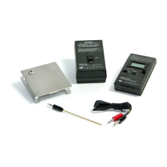
- Page 3 PFK-100 Field Meter Set I. Introduc on The PFM-711A is an accurate, compact electrosta c fi eldmeter used for loca ng and measuring sta c charge poten als. The Charge Plate Assembly CPM-720A allows the PFM-711A to be used to balance &...
- Page 4 PFM-100 Field Meter Set Hand Held by Grounded Operator (Table 1) 12 inches 18 inches 24 inches (+)Average 1.042 0.844 0.861 (-) Average 0.977 0.930 0.798 Global Ave 1.006 0.890 0.824 Table 1: Hand Held by Grounded Operator Rev. 6 / July 16, 2020...
- Page 5 PFK-100 Field Meter Set Mounted on 5lb. Weight with Grounded Wrist Strap (Table 2) 12 inches 18 inches 24 inches (+)Average 1.054 0.912 0.932 (-) Average 0.929 0.927 0.901 Global Ave 0.962 0.920 0.914 Table 2: Mounted on 5lb. Weight with Grounded Wrist Strap D.
- Page 6 PFM-100 Field Meter Set II. Cau ons & Warnings A. Do not point the PFM-711A Field Meter Ranging Lights into anyone’s eyes. CAUTION Do not point ranging lights into anyone’s eyes. B. Do not exceed 6,000 volts on CPM-720A Charge Plate Assembly. C.
- Page 7 PFK-100 Field Meter Set INTERNAL ZERO ADJUSTMENT (r27) DIGITAL DISPLAY ANALOG OUTPUT PANEL ZERO (r16) INTERNAL GAIN ADJUSTMENT (r10) RANGE/POWER SWITCH (s1) SAMPLE/HOLD BUTTON (s2) B. PFM-711A Field Meter Prepara on for use. 1. Install 9 volt ba ery provided by sliding ba ery com- partment open and fi...
-
Page 8: Operational Note
PFM-100 Field Meter Set b. Cycle the SAMPLE/HOLD bu on (s2) by pushing it a few mes; note the HOLD indica on on the meter’s display. Release SAMPLE/HOLD so that the meter is free to measure fi elds. c. Hold a fl at sheet of material in front of the meter’s sensing plate to confi rm opera on of the red ranging Bull’s Eye light system. - Page 9 PFK-100 Field Meter Set between the sensing and notched ground plates. D. CPM-720A Charge Plate Assembly Prepara on for use 1. With the PFM-711A Field Meter controls and the CPM-720A sensing plate facing up (the lower plate has a cutout for the meter), carefully slide the CPM-720A’s lower ground plate into the LOWER moun ng grooves molded into the sides of the PFM- 711A’s case.
-
Page 10: Operational Requirement
PFM-100 Field Meter Set OPERATIONAL REQUIREMENT Cases of PFM-711A fi eld meter and PCS-730 charging source MUST be grounded for proper opera on . 4. With the operator’s fi ngers contac ng the grounding snap on the back of the PFM-711A Field Meter unit, slide the three posi on (kV/inch, OFF, V/inch) RANGE/POWER switch (s1) to the kV/inch posi on. - Page 11 PFK-100 Field Meter Set F. PCS-730 Charging Source Prepara on for Use 1. Install provided 9 volt ba ery by sliding ba ery com- partment open and fi rmly snapping ba ery terminals to the appropriate connectors. Ba ery can only be con- nected in one way.
- Page 12 PFM-100 Field Meter Set Assembly and Charge the CPM-720A to approximately +1.20kV. 7. Discharge the upper plate to ground, or short the upper and lower plates, un l the PFM-711A meter reads zero. 8. With the operator’s fi ngers contac ng the metal ground- ing snap on the back of the PCS-730 Charging Source, press the three posi on rocker switch to the rear, -kV posi on.
- Page 13 PFK-100 Field Meter Set 1. Confi rming the electrosta c voltage balance of ionizer blowers and systems 2. Measuring electrosta c voltage genera on of personnel in conjunc on with footwear and fl oor surfaces. 3. Measuring electrosta c voltage genera on related to chairs, carts and equipment.
- Page 14 Follow the manufacturer’s instruc ons for normal opera ons. 2. Mount the CPM-720A Charge Plate Assembly on the PFM-711A Field Meter Case. 3. Ground the case of the PFM-711A. Note there are two ways to use Prostat devices to ground the PFM-711A/CPM-720A combina on.
- Page 15 PFK-100 Field Meter Set OPERATIONAL REQUIREMENT If documenta on of ionizer balance is required, connect the analog output of the PFM-711A to PGA-710 Autoanalysis System or an X-Y Plo er. Note that the RED analog output lead is Posi ve (+) and the BLACK is Nega ve (-). Zero the PFM- 711A/CPM-720A combina on and the X-Y Plo er to ground.
- Page 16 PFM-100 Field Meter Set 4. Select the range you wish to use for audi ng the ionizer’s decay performance. NOTE: Most accurate decay me measurements are obtained using the analog output connected to a PGA- 710 Autoanalysis System or an X-Y plo er, PDT-740B Timer or digital Mul meter. a.
- Page 17 1. Mount the CPM-720A Charge Plate Assembly on the PFM- 711A Field Meter case. 2. Ground the case of the PFM-711A, as described below. a. Using a Prostat® wrist strap cuff , mount the cuff on one of the fi ve pound NFPA electrodes found in Prostat® kits.
- Page 18 PFM-100 Field Meter Set c. Snap mount the PFM-711A’s 10 mm female snap (located on the back of the PFM-711A’s case) onto the wrist strap 10 mm male snap. d. Adjust the wrist strap cuff so that the instrument is held fi rmly to the electrode; lock the adjustment buckle.
- Page 19 PFK-100 Field Meter Set INTERNAL ZERO ADJUSTMENT (r27) DIGITAL DISPLAY ANALOG OUTPUT PANEL ZERO (r16) INTERNAL GAIN ADJUSTMENT (r10) RANGE/POWER SWITCH (s1) SAMPLE/HOLD BUTTON (s2) 1. PFM-711A Controls The PFM-711A has two switches and a rotary knob. A three-posi on slide switch (S1) pro- vides Range Selec ons and ON/OFF control.
- Page 20 Zero knob range posi on, general user maintenance is not required. The case has been sealed and BREAKING THE SEALS WILL VOID THE WARRANTY. If for any reason you believe the meter is not working correctly, contact Prostat Corpora on for assis- tance.
-
Page 21: User Caution
PFK-100 Field Meter Set USER CAUTION Other than ba ery replacement & front panel zero range adjustment, there are no user serviceable parts. Any unauthorized service will void the warranty and result in addi onal repair charges. 1. Cleaning the PFM-711A Case & Display a. - Page 22 2. User adjustment is not recommended. 3. Low output voltage is usually due to a weak ba ery or improper grounding. 4. The PCS-730 should only be serviced by Prostat or Qualifi ed Instrument Repair Technicians Opening the unit will void warranty.
- Page 23 PFK-100 Field Meter Set Specifi cations for the PFM-711A Electrostatic Field Meter High Range 0 V to ±19.99 kV (at 1” distance): Least signifi cant digit indicates volts at one inch (kV/in) in 10 Volt increments Low Range 0 V to ±1,999 V (at 1” distance): Overall Range Least signifi cant digit indicates volts at one inch (V/in) in 1 Volt invrements.
- Page 24 PFM-100 Field Meter Set Specifi cations for the PCS-730 Charging Source 9 Volts Alkaline Battery. Input Power Battery life in excess of 40 hours continuous operation ±1,250 ±5% volts DC Output Current limited to less than 1 Microamp. Output Connector Female banana jack provided with mating contact wand.
- Page 25 PFK-100 Field Meter Set NOTES Rev. 6 / July 16, 2020...
- Page 26 PFM-100 Field Meter Set NOTES Rev. 6 / July 16, 2020...
- Page 28 Specifi ca ons are subject to change without no ce. All Prostat trademarks and trade names are the property of Prostat Corpora on. All other trademarks and trade names are the property of their respec ve companies. P R O F E S S I O N A L...
Need help?
Do you have a question about the PFK-100 and is the answer not in the manual?
Questions and answers