Table of Contents
Advertisement
Advertisement
Table of Contents

Related Manuals for Prostat PRS-812


Summary of Contents for Prostat PRS-812
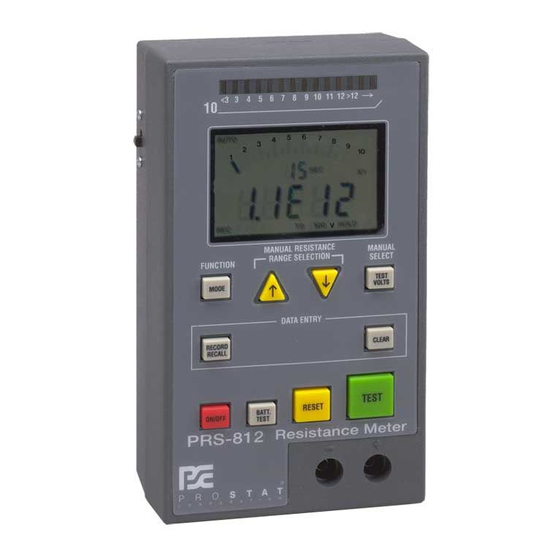
- Page 1 RESISTANCE METER PRS-812 User Manual...
-
Page 3: Table Of Contents
General Specifications Instrument Controls Copyright © 2012 by Prostat® Corporation. All rights reserved. Printed in the United States of America. No part of this manual may be used or reproduced in any manner whatsoever without written permission. For information contact Prostat Corporation, 1072 Tower Lane, Bensenville, IL 60106 USA Prostat is the registered trademark of Prostat®... -
Page 4: Introduction & Description
5% of tolerance, and those between 1.0 and 1.0x10 ohms are within 0.5% of laboratory references While quite sophisticated in design, the PRS-812 Resistance Meter is easy to use and extremely helpful in making accurate ESD auditing measurements, or general resistance and continuity checks. CAUTION To avoid electrical shock or damage to the PRS-812 Resistance Meter, read this manual completely before installing batteries or using the instrument. - Page 5 Optional accessories are available for the PRS-812 Resistance Meter. Visit www.prostatcorp.com for additional information. C. PRS-812 Basic Description & Functions The PRS-812 Resistance Meter has several test, display and data logging functions: 1. The PRS-812 six basic measurement modes are described in the following table Rev. C / January 2012...
- Page 6 @ 10V: 1.0E+04 TO <1.0E+06Ω (10KΩ - < 1MΩ) @100V: 1.0E+06 TO <2.0E+12Ω (1MΩ - <200TΩ) See Note Below 2. The PRS-812 provides three separate test voltages for resistance measurements as indicated in the table, above: <10 Volts 10 Volts...
-
Page 7: Cautions & Warnings
Digital measurements are provided using integers and Ω, KΩ, MΩ, GΩ, TΩ indicators, or in exponential format (1.0EXX) with Ω -TΩ indicators. 4. The PRS-812 includes data logging (storage) capabilities for up to 80 data points when RECORD is selected. The instrument will provide access to the memory register, calculate and display Minimum, Maximum and Average of all measurements in the instrument’s memory whenever... - Page 8 CAUTION or WARNING headings throughout this publication flag this infor- mation, where appropriate. Follow all caution and warning instructions at all times. 2. The PRS-812 is a precision instrument and should be operated by experienced personnel famil- iar with the use and handling of devices containing power supplies.
-
Page 9: Controls, Connections & Indicators
Unauthorized opening of the PRS-801 case or dismantling in any manner WILL VOID THE INSTRUMENT’S WARRANTY. 4. Read this manual in its entirety before installing batteries or using the PRS-812. 5. Do not drop or cause unnecessary mechanical shock to your PRS-812 instrument. - Page 10 (6) AUTO-MANUAL: displays data in Ω, KΩ, MΩ, GΩ and TΩ In AUTO-MANUAL the operator may select the initial resistance range in decade increments. Once set, the PRS-812 starts the measurement process from the preset resistance decade, rather than re-zeroing itself for each measurement.
- Page 11 PRS-812 Resistance Meter [2] RESISTANCE RANGE SELECTION Two Triangular Arrows Buttons, UP (↑) and DOWN (↓), select Resistance Measurement Range in single orders of magnitude while in MANUAL or AUTOMATIC/MANUAL modes [3] TEST VOLTS Manual Selection of <10, 10 or 100 volts in MANUAL selects initial test voltage.
- Page 12 PRS-812 Resistance Meter NOTE If RECALL is not pressed, a fifth time OOPS will be displayed in the LCD when TEST is next pressed. To Clear OOPS, press RESET. The instrument will return to normal operations. [5] CLEAR In normal operations CLEAR erases data in Memory Register, discards most recent measurement, or turns the REC function OFF as follows: a.
- Page 13 Switch battery buss to the OFF position before changing batteries to avoid re- verse polarity damage to the instrument. LCD DISPLAY ELEMENTS [11] Colored LED’s 14 LED’s across the top of the PRS-812 indicate measurement order of mag- nitude in decades from <10 to >10 ohms.
- Page 14 PRS-812 Resistance Meter Displayed when RECALL button is pushed second time while in REC mode. Number displayed when MIN is indicated is the Minimum data value in Memory Register. Displayed when RECALL button is pushed a third time (sequentially) in REC mode.
-
Page 15: Battery Installation And Replacement
PRS-812 Resistance Meter Battery Compartment Located in lower section of case, opposite LCD display. Holds two 9V-transistor batteries. Two screws secure the battery cover. Note: Use only Long Life Alkaline Batteries. Remove batteries when instrument is not in use for long periods of time. -
Page 16: Setup & Calibration
6.75 volts, replace both batteries. V. Setup & Calibration A. Setting up the PRS-812 for low resistance range calibration 1. Position Battery Buss Cut Off switch to OFF position 2. To install batteries, remove two Phillips locking screws and cover. Attach two Long-Life, Alkaline 9V batteries to the battery connection terminals. - Page 17 PRS-812 Resistance Meter Figure 5: Low Resistance Range Calibration Shunt Installation 2. Press the Red ON/OFF power button. The instrument display should become energized, each LED will be tested in sequence, and GOOD will is displayed in the LCD if the batteries have sufficient test capacity (figure 9).
-
Page 18: Instrument Operation
VI. Instrument Operation A. Overview of PRS-812 Operation & Measurement Test Cycle Sequence The following 10 points provide a general overview for calibrating and using the PRS-812 for resis- tance measurements. 1. Slide Battery Buss Cut Off switch to ON 2. - Page 19 Electrification period, i.e., the time period during which test voltage is applied to the ma- terial under test, is automatically adjusted to the PRS-812’s measurement characteristics and industry standards (ANSI/ESD STM11.11). Typical electrification periods are: 2 to 3 Seconds: 0.1 to less than 1.0x10 ohms (0.1Ω...
- Page 20 NOTE: When several “held” measurements vary greater than 15 to 20 percent of each other this typically indicates inconsistencies in the material or test conditions. 9. To save the displayed measurement in the Memory Register and prepare the PRS-812 for the next measurement, press the Yellow RESET button. Pressing RESET causes three functions: a.
- Page 21 As with most very precise instruments, the PRS-812 circuits and its cables are sensitive to the ef- fects of electromagnetic and electrostatic fields. These effects are minimized by instrument and test lead design.
- Page 22 Refer to National Electrical Codes and ESD Association Standard S6.1 Grounding for information and procedures. Only qualified personnel should conduct ground test measurements. 2. Use only Prostat test leads, cables and accessories supplied with the PRS-812. Be sure that leads are properly connected to their respective terminals as described below.
- Page 23 AUTO Mode 2: Auto Display in Ω, KΩ, MΩ, GΩ and TΩ indicators AUTO Mode 1 is the default functional mode when the PRS-812 is powered up. To change to AUTO Mode 2, simply press the MODE button once. The AUTOMATIC modes are used in measurements where the following attributes are desired: →...
- Page 24 Figure 9: PRS-812 Power Up tests display circuits, LED indicators and batteries 5. AUTO is displayed in the LCD. a. The default Mode for the PRS-812 is Automatic Resistance Measurement in exponential format (1.0EXX). b. If measurements are to be displayed in Ohms press the Gray MODE button once.
- Page 25 Test Voltage Indicators is Complete is Complete Indicators Figure 10: Comparing PRS-812 Display in Automatic Ohms Mode and Automatic Exponential Mode after the same low resistance measurement. F. Measurements from 1.0x10 to less than 1.0x10 ohms: 1. When the resistance measurement is greater than 1.0x10 ohms test voltage will automatically be increased to 10 volts, and the resistance range will be adjusted as necessary.
- Page 26 Figure 12: Test Voltage at 100 Volts from 1.0E+06 to 1.0E+14 Ohms in Auto NOTE The PRS-812 can obtain an accurate resistance measurement within 2.5 seconds up to 1.0x10 ohms, depending on material characteristics. An additional 5.0 seconds of electrification is applied in accordance with ESD Association S11.11 Surface Resistance Standard.
- Page 27 3. Once a stable measurement is confirmed and displayed by the instrument, HOLD will be dis- played in the LCD and the electrification timer will stop. NOTE The PRS-812 provides very accurate measurements up to 1.0x10 ohms, and has the capability to display values up to 2.0x10 ohms.
- Page 28 PRS-812 Resistance Meter 5. Set test voltage by pressing MANUAL SELECT TEST VOLTS button until the desired voltage is displayed in lower right portion of LCD, i.e., <10, 10 or 100 Volts. MANUAL Test Voltage & Re- sistance Limits are defined below.
- Page 29 When AUTOMATIC electrification period and Test Voltage control must be maintained to current industry (and Automatic Mode) settings This mode prevents the PRS-812 from resetting the Test Voltage and Resistance Range to Mini- mum at the beginning of each Measurement Test Cycle. In this mode, measurements start at the resistance range selected by the operator, and its commensurate Test Voltage, or the value of the last measurement Otherwise, it is used similar to the AUTOMATIC Mode.
- Page 30 Initial Test Voltage for the selected resistance decade will be applied. For example if the 10 ohms decade was selected, initial Test Voltage will be 100 Volts. c. At this point the PRS-812’s AUTOMATIC Mode takes control of the Measurement Test Cycle: Automatically re-adjusts RESISTANCE RANGE in accordance with material...
-
Page 31: Instrument Maintenance
VII. Instrument Maintenance A. Calibration & Repair 1. Instrument Calibration should be performed annually 2. Only Prostat Corporation or their authorized instrument laboratory should perform PRS-812 calibration or repair. 3. Before shipping your instrument to Prostat Corporation for service, contact Prostat calibration &... -
Page 32: Warranty Information
Limit of Liability – in no event will Prostat or any seller be responsible or liable for special, incidental, or consequential losses or damages, under any legal theory including but not limited to contract, negligence, or strict liability. - Page 33 Website: prostatcorp.com/rma C. Shipping Non-Warranty Items 1. Any Prostat product returned for non-warranty repair or calibration requires a Return Materials Authorization (RMA) number and should be packaged and shipped as described above, and as directed by Prostat’s customer service department.
-
Page 34: General Specifications
PRS-812 Resistance Meter PRS-812 Resistance System Specifications Range: Resistance from <0.1 (1.0E-1) Ohms to 200 Tera ohms (1.0E+12 ohms). Maximum resistance indication: 200 Tera ohms (2.0E+14 ohms) Test Voltages: Automatic mode Default: <0.01 to 10 volts Variable 1.0E-1 to 1.0E+4 Ohms Constant Voltage 10 volts ±... -
Page 35: Instrument Controls
PRS-812 Resistance Meter PRS-812 Instrument Controls FUNCTION/ MODE Toggles Through Six (6) Operation Modes: DISPLAYED INDICA- RESIST. TEST TEST MODE UNITS TION RANGE VOLTS FUNCTIONS AUTOMATIC 1 1.0EXX AUTOMATIC RESISTANCE RANGE, AUTO AUTO. AUTO. [Default] IND Ω - TΩ TEST VOLTS, ELECTRIFICATION,... - Page 36 PRS-812 Resistance Meter ter. Calculates and Displays Minimum, Maximum and Average of data stored in Memory Register. Clear Erases data in Memory Register; if in HOLD mode, discards most recent Held Value ON/OFF Power-up, perform functional & Battery tests, Power-down if ON.
- Page 37 PRS-812 Resistance Meter NOTES Rev. C / January 2012...
- Page 38 PRS-812 Resistance Meter NOTES Rev. C / January 2012...
- Page 40 Specifications are subject to change without notice. All Prostat trademarks and trade names are the property of Prostat Corporation. All other trademarks and trade names are the property of their respective companies. P R O F E S S I O N A L...
Need help?
Do you have a question about the PRS-812 and is the answer not in the manual?
Questions and answers